nju实验一 选择器
 本次实验将介绍几种常用的多路选择器的设计方法;Verilog语言中的always语句块、if-else语句和case语句的使用等。最后请读者自行设计一个多路选择器,熟悉电路设计的基本流程和Quartus的使用。
实验一选择器
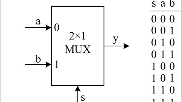
2选1多路选择器
.
├── constr
│ └── top.nxdc
├── csrc
│ └── test_our.cpp
├── Makefile
├── vsrc
│ └── top.v
├── top.v
├── vlt_dump.vcd
├── test_our.cpp
├── obj_dir
└── dump.vcd
├── constr
└── top.nxdc
top = top

led (LD15, LD14, LD13, LD12, LD11, LD10, LD9, LD8, LD7, LD6, LD5, LD4, LD3, LD2, LD1, LD0)
rst BTNL
├── csrc
└── test_our.cpp
#include<nvboard.h>
#include<Vtop.h>

static TOP_NAME dut;

void nvboard_bind_all_pins(TOP_NAME* top);

static void single_cycle(){
    dut.eval();
}

int main(){
	nvboard_bind_all_pins(&dut);
	nvboard_init();

	while(1){
		nvboard_update();
		single_cycle();
	}

}
1.头文件引入
●Vtop.h:由 Verilator 从 Verilog 文件(top.v)生成,包含仿真模型。
nvboard.h:提供 FPGA 信号的可视化(如按钮、LED、七段数码管等)。
2.全局变量定义
●dut (Device Under Test):表示被测的 Verilog 模块(TOP_NAME 通常是 Vtop,由 Verilator 生成)。
●static 限制作用域仅在当前文件。
3.NVBoard 引脚绑定
作用:将 Verilog 模块的输入/输出信号绑定到 NVBoard 的虚拟外设(按键、LED 等)。
实现:在另一个文件( top.nxdc
)中定义。
4.单时钟周期仿真
●功能:模拟一个完整的时钟周期:
●关键点:
○eval() 是 Verilator 生成的函数,会调用 Vtop___024root___eval 计算信号值。
5.主函数
●流程:
○初始化:
■绑定 Verilog 信号到 NVBoard 的虚拟外设。
■启动 NVBoard 的可视化界面。
○主循环:
■nvboard_update():读取用户输入(如按键按下)并更新 Verilog 输入信号(如 dut.a)。
■single_cycle():执行一个时钟周期的仿真,更新输出信号(如 dut.f 会驱动 LED)。
├── test_our.cpp
#include "verilated.h"
#include "verilated_vcd_c.h"
#include "obj_dir/Vtop.h"
VerilatedContext* contextp = NULL;
VerilatedVcdC* tfp = NULL;
static Vtop* top;
void step_and_dump_wave(){
top->eval();
contextp->timeInc(1);
tfp->dump(contextp->time());
}
void sim_init(){
contextp = new VerilatedContext;
tfp = new VerilatedVcdC;
top = new Vtop;
contextp->traceEverOn(true);
top->trace(tfp, 0);
tfp->open("dump.vcd");
}
void sim_exit(){
step_and_dump_wave();
tfp->close();
}
int main() {
sim_init();
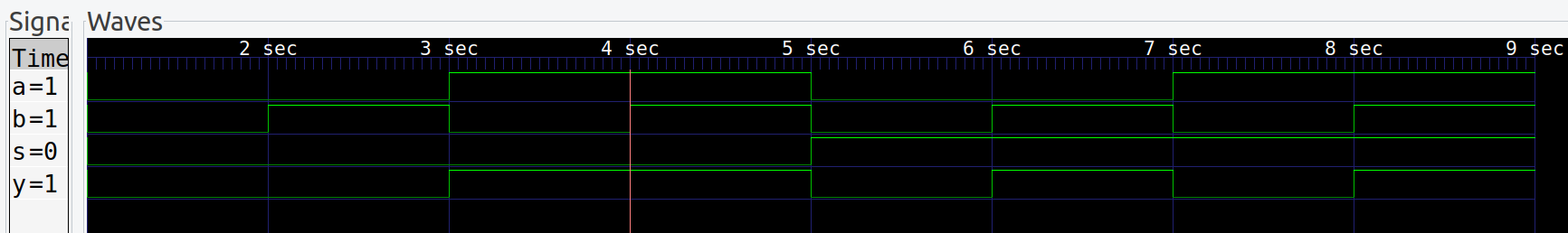
top->s=0; top->a=0; top->b=0; step_and_dump_wave();
top->b=1; step_and_dump_wave();
top->a=1; top->b=0; step_and_dump_wave();
top->b=1; step_and_dump_wave();
top->s=1; top->a=0; top->b=0; step_and_dump_wave();
top->b=1; step_and_dump_wave();
top->a=1; top->b=0; step_and_dump_wave();
top->b=1; step_and_dump_wave();
sim_exit();
}
1.头文件引入
●Vtop.h:由 Verilator 从 Verilog 文件(top.v)生成,包含仿真模型。
●verilated_vcd_c.h:提供生成 VCD 波形文件的功能,可用于 GTKWave 等工具查看信号时序。
2.全局变量定义
●contextp:管理仿真时间、调试信息等。
●tfp:用于写入 VCD 波形数据。
●top:Verilog 顶层模块的实例( module top)。
3.仿真初始化 (sim_init)
●功能:
○创建仿真上下文和 VCD 文件对象。
○实例化 Verilog 模块(Vtop)。
○配置信号追踪,生成 dump.vcd 文件。
4.单步仿真和波形记录 (step_and_dump_wave)
●eval():评估 Verilog 模块的逻辑(更新输出信号)。
●timeInc(1):推进仿真时间(单位由用户定义,这里为 1)。
●dump():将信号值写入 VCD 文件。
5.仿真结束处理 (sim_exit)
确保仿真结束时,最后一次信号状态被记录。
6.主函数 (main)
●功能:遍历输入信号 s、a、b 的所有组合(共 8 种情况),观察输出变化。
●每个步骤:
○设置输入信号(如 s=0, a=0, b=0)。
○调用 step_and_dump_wave() 执行仿真并记录波形。
├── vsrc
└── top.v
module my_and(a,b,c);
  input  a,b;
  output c;

  assign c = a & b;
endmodule

module my_or(a,b,c);
  input  a,b;
  output c;

  assign c = a | b;
endmodule

module my_not(a,b);
  input  a;
  output b;

  assign b = ~a;
endmodule

module top(a,b,s,y);
  input  a,b,s;
  output y;

  wire l, r, s_n; // 内部网线声明
  my_not i1(.a(s), .b(s_n));        // 实例化非门,实现~s
  my_and i2(.a(s_n), .b(a), .c(l)); // 实例化与门,实现(~s&a)
  my_and i3(.a(s),   .b(b), .c(r)); // 实例化与门,实现(s&b)
  my_or  i4(.a(l),   .b(r), .c(y)); // 实例化或门,实现(~s&a)|(s&b)
endmodule
├── top.v
module top(a,b,s,y);
  input   a,b,s;        // 声明3个wire型输入变量a,b,和s,其宽度为1位。
  output  y;           // 声明1个wire型输出变量y,其宽度为1位。

  assign  y = (~s&a)|(s&b);  // 实现电路的逻辑功能。

endmodule
波形仿真
(1)编译
verilator -Wall --trace -cc top.v --exe main.cpp
(2)生成可执行文件
 make -C obj_dir -f Vtop.mk Vtop
(3)生成波形
./obj_dir/Vtop
(4)查看波形
gtkwave dump.vcd
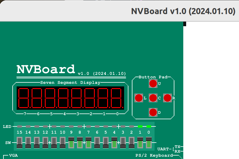
接入NVBoard
make
cd build
./top
4选1多路选择器
.
├── constr
│ └── top.nxdc
├── csrc
│ └── test_our.cpp
├── Makefile
├── vsrc
│ └── top.v
├── top.v
├── vlt_dump.vcd
├── test_our.cpp
├── obj_dir
└── dump.vcd
├── constr
└── top.nxdc
top=top

y (LD0)
s (SW1, SW0)
a (SW5, SW4, SW3, SW2)
├── csrc
└── test_our.cpp
#include<nvboard.h>
#include<Vtop.h>

static TOP_NAME dut;

void nvboard_bind_all_pins(TOP_NAME* top);

static void single_cycle(){
    dut.eval();
}

int main(){
	nvboard_bind_all_pins(&dut);
	nvboard_init();

	while(1){
		nvboard_update();
		single_cycle();
	}

}
├── test_our.cpp
#include "verilated.h"
#include "verilated_vcd_c.h"
#include "obj_dir/Vtop.h"
VerilatedContext* contextp = NULL;
VerilatedVcdC* tfp = NULL;
static Vtop* top;
void step_and_dump_wave(){
top->eval();
contextp->timeInc(1);
tfp->dump(contextp->time());
}
void sim_init(){
contextp = new VerilatedContext;
tfp = new VerilatedVcdC;
top = new Vtop;
contextp->traceEverOn(true);
top->trace(tfp, 0);
tfp->open("dump.vcd");
}
void sim_exit(){
step_and_dump_wave();
tfp->close();
}
int main() {
sim_init();
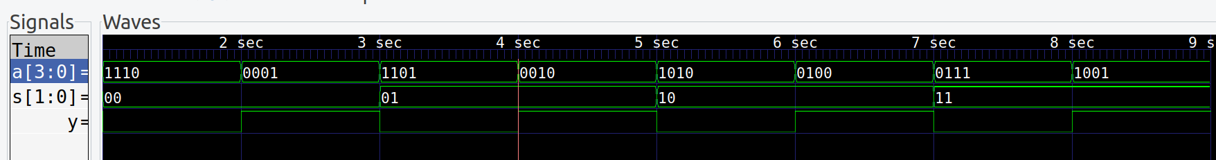
top->s=0b00; top->a=0b1110; step_and_dump_wave();
top->a=0b0001; step_and_dump_wave();
top->s=0b01; top->a=0b1101; step_and_dump_wave();
top->a=0b0010; step_and_dump_wave();
top->s=0b10; top->a=0b1010; step_and_dump_wave();
top->a=0b0100; step_and_dump_wave();
top->s=0b11; top->a=0b0111; step_and_dump_wave();
top->a=0b1001; step_and_dump_wave();
sim_exit();
}
├── vsrc
└── top.v
module top(a,b,s,y);
  input   a,b,s;        // 声明3个wire型输入变量a,b,和s,其宽度为1位。
  output  y;           // 声明1个wire型输出变量y,其宽度为1位。

  assign  y = (~s&a)|(s&b);  // 实现电路的逻辑功能。

endmodule
├── top.v
module top(a,b,s,y);
  input   a,b,s;        // 声明3个wire型输入变量a,b,和s,其宽度为1位。
  output  y;           // 声明1个wire型输出变量y,其宽度为1位。

  assign  y = (~s&a)|(s&b);  // 实现电路的逻辑功能。

endmodule
波形仿真
(1)编译
verilator -Wall --trace -cc top.v --exe main.cpp
(2)生成可执行文件
 make -C obj_dir -f Vtop.mk Vtop
(3)生成波形
./obj_dir/Vtop
(4)查看波形
gtkwave dump.vcd
接入NVBoard
make
cd build
./top
4选1多路选择器(2位)
.
├── constr
│ └── top.nxdc
├── csrc
│ └── test_our.cpp
├── Makefile
├── vsrc
│ └── top.v
├── top.v
├── vlt_dump.vcd
├── test_our.cpp
├── obj_dir
└── dump.vcd
├── constr
└── top.nxdc
top=top

f (LD1, LD0)
y (SW1, SW0)

x0 (SW3, SW2)
x1 (SW5, SW4)
x2 (SW7, SW6)
x3 (SW9, SW8)
├── csrc
└── test_our.cpp
#include<nvboard.h>
#include<Vtop.h>

static TOP_NAME dut;

void nvboard_bind_all_pins(TOP_NAME* top);

static void single_cycle(){
    dut.eval();
}

int main(){
	nvboard_bind_all_pins(&dut);
	nvboard_init();

	while(1){
		nvboard_update();
		single_cycle();
	}

}
├── test_our.cpp
#include "verilated.h"
#include "verilated_vcd_c.h"
#include "obj_dir/Vtop.h"
VerilatedContext* contextp = NULL;
VerilatedVcdC* tfp = NULL;
static Vtop* top;
void step_and_dump_wave(){
top->eval();
contextp->timeInc(1);
tfp->dump(contextp->time());
}
void sim_init(){
contextp = new VerilatedContext;
tfp = new VerilatedVcdC;
top = new Vtop;
contextp->traceEverOn(true);
top->trace(tfp, 0);
tfp->open("dump.vcd");
}
void sim_exit(){
step_and_dump_wave();
tfp->close();
}
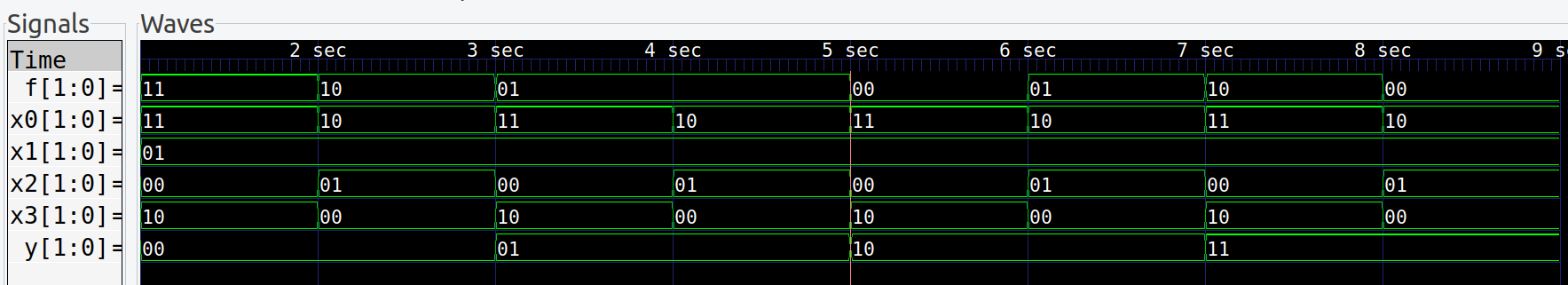
int main() {
sim_init();
top->y=0b00; top->x0=0b11; top->x1=0b01; top->x2=0b00; top->x3=0b10; step_and_dump_wave();
top->x0=0b10; top->x1=0b01; top->x2=0b01; top->x3=0b00; step_and_dump_wave();
top->y=0b01; top->x0=0b11; top->x1=0b01; top->x2=0b00; top->x3=0b10; step_and_dump_wave();
top->x0=0b10; top->x1=0b01; top->x2=0b01; top->x3=0b00; step_and_dump_wave();
top->y=0b10; top->x0=0b11; top->x1=0b01; top->x2=0b00; top->x3=0b10; step_and_dump_wave();
top->x0=0b10; top->x1=0b01; top->x2=0b01; top->x3=0b00; step_and_dump_wave();
top->y=0b11; top->x0=0b11; top->x1=0b01; top->x2=0b00; top->x3=0b10; step_and_dump_wave();
top->x0=0b10; top->x1=0b01; top->x2=0b01; top->x3=0b00; step_and_dump_wave();
sim_exit();
}
├── vsrc
└── top.v
module top(x0, x1, x2, x3, y, f);
  input  [1:0] x0;
  input  [1:0] x1;
  input  [1:0] x2;
  input  [1:0] x3;
  input  [1:0] y;  // 声明一个wire型输入变量s,其变量宽度是2位的。
  output reg [1:0] f;   // 声明一个2位reg型的输出变量y。

  always @ (*)
    case (y)
      2'b00: f = x0;
      2'b01: f = x1;
      2'b10: f = x2;
      2'b11: f = x3;
      default: f = 2'b00;
    endcase

endmodule
module top(a,b,s,y);
  input   a,b,s;        // 声明3个wire型输入变量a,b,和s,其宽度为1位。
  output  y;           // 声明1个wire型输出变量y,其宽度为1位。

  assign  y = (~s&a)|(s&b);  // 实现电路的逻辑功能。

endmodule
├── top.v
module top(x0, x1, x2, x3, y, f);
  input  [1:0] x0;
  input  [1:0] x1;
  input  [1:0] x2;
  input  [1:0] x3;
  input  [1:0] y;  // 声明一个wire型输入变量s,其变量宽度是2位的。
  output reg [1:0] f;   // 声明一个2位reg型的输出变量y。

  always @ (*)
    case (y)
      2'b00: f = x0;
      2'b01: f = x1;
      2'b10: f = x2;
      2'b11: f = x3;
      default: f = 2'b00;
    endcase

endmodule
module top(a,b,s,y);
  input   a,b,s;        // 声明3个wire型输入变量a,b,和s,其宽度为1位。
  output  y;           // 声明1个wire型输出变量y,其宽度为1位。

  assign  y = (~s&a)|(s&b);  // 实现电路的逻辑功能。

endmodule
波形仿真
(1)编译
verilator -Wall --trace -cc top.v --exe main.cpp
(2)生成可执行文件
 make -C obj_dir -f Vtop.mk Vtop
(3)生成波形
./obj_dir/Vtop
(4)查看波形
gtkwave dump.vcd
接入NVBoard
make
cd build
./top

 浙公网安备 33010602011771号