
OpenCVSharp:学习连通性检测的使用
连通性检测
连通性检测是计算机视觉中的一种基础图像处理技术,用于识别和标记二值图像中相互连接的像素区域。简单来说,它能够找出图像中所有独立的"连通区域"(即像素之间相互连接形成的区域)。
应用场景
更多的是其它图像处理的一个前置步骤,可能有时候可以用来统计物体数量,但是使用场景很有限。
效果
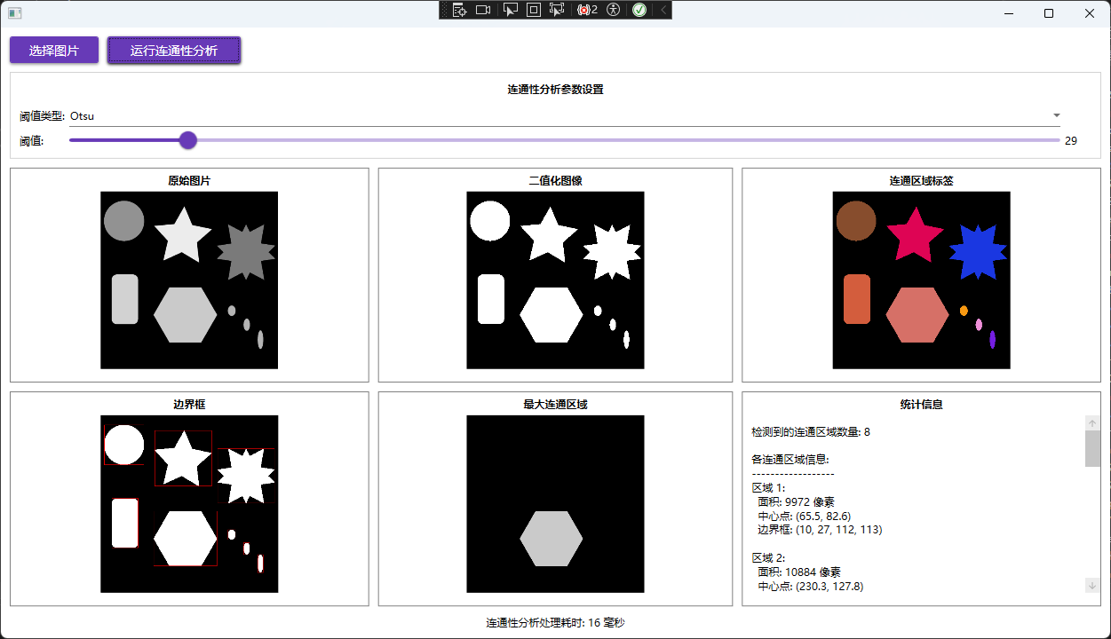
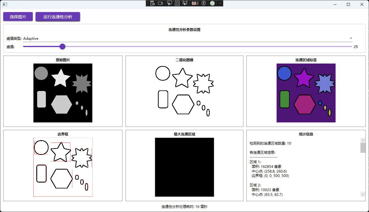
实践
图像灰度化
首先需要将图像转化为灰度图:
// 转换为灰度图像
using var gray = src.CvtColor(ColorConversionCodes.BGR2GRAY);
灰度图是一种只包含亮度信息而不包含颜色信息的图像表示方式,它将彩色图像中的每个像素转换为从黑色(最暗)到白色(最亮)的256个灰度级别中的一个值,通常用0-255的数值来表示,其中0代表纯黑色,255代表纯白色,中间值代表不同深浅的灰色。
图像二值化
然后再将灰度图转化为二值图像:
 // 二值化处理
 using var binary = new Mat();
 ThresholdTypes thresholdType = GetThresholdType();

 if (ThresholdType == "Adaptive")
 {
     Cv2.AdaptiveThreshold(gray, binary, 255, AdaptiveThresholdTypes.MeanC, ThresholdTypes.Binary, 11, 2);
 }
 else
 {
     Cv2.Threshold(gray, binary, ThresholdValue, 255, thresholdType);
 }

 private ThresholdTypes GetThresholdType()
 {
     return ThresholdType switch
     {
         "Otsu" => ThresholdTypes.Otsu,
         "Binary" => ThresholdTypes.Binary,
         _ => ThresholdTypes.Otsu
     };
 }
这里展示了OpenCVSharp中进行图像二值化的两种方法,分别是Cv2.AdaptiveThreshold与Cv2.Threshold。
先来看下Cv2.AdaptiveThreshold:
public static void AdaptiveThreshold(InputArray src, OutputArray dst,
    double maxValue, AdaptiveThresholdTypes adaptiveMethod, ThresholdTypes thresholdType, int blockSize, double c)
{
    if (src is null)
        throw new ArgumentNullException(nameof(src));
    if (dst is null)
        throw new ArgumentNullException(nameof(dst));
    src.ThrowIfDisposed();
    dst.ThrowIfNotReady();

    NativeMethods.HandleException(
        NativeMethods.imgproc_adaptiveThreshold(src.CvPtr, dst.CvPtr, maxValue, (int) adaptiveMethod, (int)thresholdType, blockSize, c));

    GC.KeepAlive(src);
    GC.KeepAlive(dst);
    dst.Fix();
}
AdaptiveThreshold 方法是OpenCV中的一个自适应阈值处理函数,它的主要作用是对图像进行局部自适应的二值化处理。
与全局阈值处理不同,它不是对整个图像使用单一的阈值,而是根据图像中每个像素周围的局部区域动态计算阈值。这种方法特别适用于光照不均匀的图像,能够更好地处理图像中不同区域亮度差异较大的情况。
该方法通过计算每个像素周围邻域的平均值或高斯加权平均值,然后减去一个常数c来得到局部阈值,最后根据这个局部阈值对像素进行二值化。在连通性分析应用中,自适应阈值能够在光照不均匀的情况下产生比全局阈值更好的二值化效果,从而提高连通区域检测的准确性。
看一下这个方法的参数:
| 参数名 | 含义 |
|---|---|
| src | 源图像,必须是8位单通道图像(通常是灰度图) |
| dst | 目标图像,与源图像具有相同的大小和类型 |
| maxValue | 满足条件的像素被赋予的非零值(通常是255) |
| adaptiveMethod | 自适应阈值算法:ADAPTIVE_THRESH_MEAN_C(局部平均值)或 ADAPTIVE_THRESH_GAUSSIAN_C(高斯加权平均值) |
| thresholdType | 阈值类型,必须是 THRESH_BINARY 或 THRESH_BINARY_INV |
| blockSize | 用于计算阈值的像素邻域大小,必须是奇数(如3, 5, 7等) |
| c | 从平均值或加权平均值中减去的常数,可以是正数、零或负数 |
再看一下AdaptiveThresholdTypes:
| 枚举值 | 数值 | 描述 | 计算方式 |
|---|---|---|---|
| MeanC | 0 | 均值自适应阈值 | 计算block_size × block_size像素邻域的均值,然后减去param1 |
| GaussianC | 1 | 高斯加权自适应阈值 | 计算block_size × block_size像素邻域的高斯加权和,然后减去param1 |
再来看下Cv2.Threshold:
public static double Threshold(InputArray src, OutputArray dst, double thresh, double maxval, ThresholdTypes type)
{
    if (src is null)
        throw new ArgumentNullException(nameof(src));
    if (dst is null)
        throw new ArgumentNullException(nameof(dst));
    src.ThrowIfDisposed();
    dst.ThrowIfNotReady();

    NativeMethods.HandleException(
        NativeMethods.imgproc_threshold(src.CvPtr, dst.CvPtr, thresh, maxval, (int)type, out var ret));

    GC.KeepAlive(src);
    GC.KeepAlive(dst);
    dst.Fix();
    return ret;
}
Threshold 方法对输入图像的每个像素应用固定级别的阈值处理,将灰度图像转换为二值图像或进行其他类型的阈值变换。这是图像处理中的基本操作,常用于图像分割、特征提取等场景。
看一下这个方法的参数:
| 参数名 | 类型 | 含义 |
|---|---|---|
| src | InputArray | 输入数组(单通道,8位或32位浮点类型) |
| dst | OutputArray | 输出数组,与src具有相同的大小和类型 |
| thresh | double | 阈值,用于判断像素值的分界点 |
| maxval | double | 最大值,用于THRESH_BINARY和THRESH_BINARY_INV阈值类型 |
| type | ThresholdTypes | 阈值类型,决定了如何应用阈值 |
再看一下阈值类型:
| 枚举值 | 数值 | 描述 | 计算公式 |
|---|---|---|---|
| Binary | 0 | 二值化阈值 | src(x,y) > thresh ? maxval : 0 |
| BinaryInv | 1 | 反向二值化阈值 | src(x,y) > thresh ? 0 : maxval |
| Trunc | 2 | 截断阈值 | src(x,y) > thresh ? thresh : src(x,y) |
| Tozero | 3 | 零化阈值 | src(x,y) > thresh ? src(x,y) : 0 |
| TozeroInv | 4 | 反向零化阈值 | src(x,y) > thresh ? 0 : src(x,y) |
| Mask | 7 | 掩码值 | - |
| Otsu | 8 | 使用Otsu算法自动选择最佳阈值 | 自动计算最优阈值 |
| Triangle | 16 | 使用Triangle算法自动选择最佳阈值 | 自动计算最优阈值 |
比较常用的就是Binary与Otsu。
连通性检测
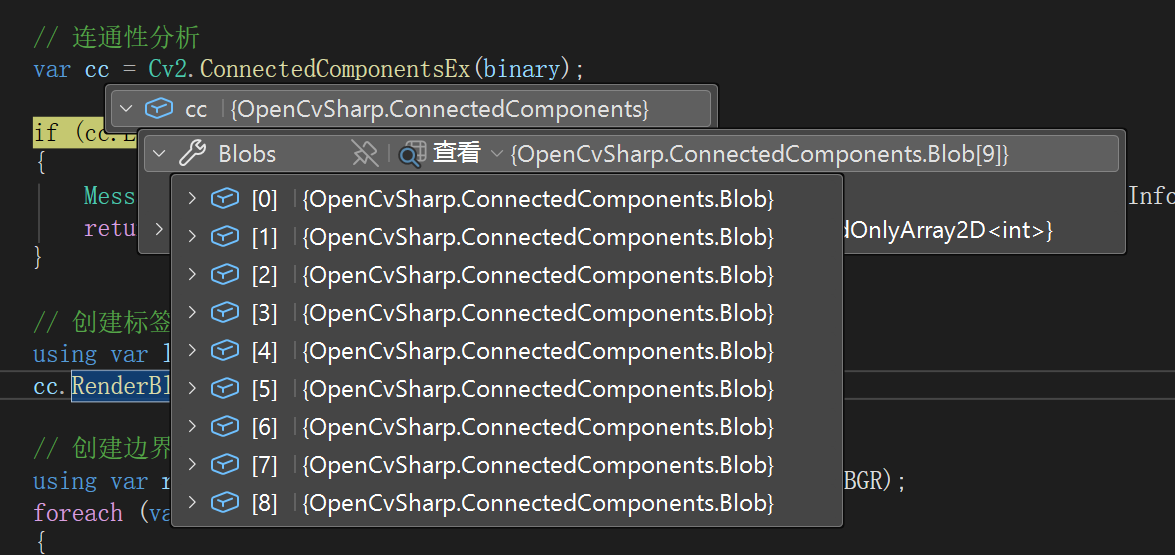
在OpenCVSharp中对二值图像进行连通性分析一行代码就行:
// 连通性分析
var cc = Cv2.ConnectedComponentsEx(binary);
现在看下Cv2.ConnectedComponentsEx:
 public static ConnectedComponents ConnectedComponentsEx(
     InputArray image,
     PixelConnectivity connectivity = PixelConnectivity.Connectivity8,
     ConnectedComponentsAlgorithmsTypes ccltype = ConnectedComponentsAlgorithmsTypes.Default)
 {
     using var labelsMat = new Mat<int>();
     using var statsMat = new Mat<int>();
     using var centroidsMat = new Mat<double>();
     var nLabels = ConnectedComponentsWithStatsWithAlgorithm(
         image, labelsMat, statsMat, centroidsMat, connectivity, MatType.CV_32S, ccltype);
     var labels = labelsMat.ToRectangularArray();
     var stats = statsMat.ToRectangularArray();
     var centroids = centroidsMat.ToRectangularArray();

     var blobs = new ConnectedComponents.Blob[nLabels];
     for (var i = 0; i < nLabels; i++)
     {
         blobs[i] = new ConnectedComponents.Blob
         {
             Label = i,
             Left = stats[i, 0],
             Top = stats[i, 1],
             Width = stats[i, 2],
             Height = stats[i, 3],
             Area = stats[i, 4],
             Centroid = new Point2d(centroids[i, 0], centroids[i, 1]),
         };
     }
     return new ConnectedComponents(blobs, labels, nLabels);
 }
ConnectedComponentsEx 函数计算布尔图像的连通组件标记图像,支持4邻域或8邻域连通性。它返回一个包含所有标记信息的结构化对象,其中标签0代表背景,其他标签[1, N-1]代表不同的前景连通区域。
| 参数名 | 含义 |
|---|---|
| image | 需要进行标记的输入图像,通常是二值图像 |
| connectivity | 连通性类型,默认为8邻域连通。Connectivity8表示8邻域连通(上下左右+对角线),Connectivity4表示4邻域连通(仅上下左右) |
| ccltype | 连通组件算法类型,默认为Default。指定用于连通组件分析的算法 |
现在我们得到了很多区域:
现在我们想将所有检测到的连通区域(blobs)以不同颜色渲染到目标图像上。
// 创建标签图像
using var labelView = src.EmptyClone();
cc.RenderBlobs(labelView);

 public void RenderBlobs(Mat img)
 {
     if (img is null)
         throw new ArgumentNullException(nameof(img));
     /*
     if (img.Empty())
         throw new ArgumentException("img is empty");
     if (img.Type() != MatType.CV_8UC3)
         throw new ArgumentException("img must be CV_8UC3");*/
     if (Blobs is null || Blobs.Count == 0)
         throw new OpenCvSharpException("Blobs is empty");
     if (Labels is null)
         throw new OpenCvSharpException("Labels is empty");

     var height = Labels.GetLength(0);
     var width = Labels.GetLength(1);
     img.Create(new Size(width, height), MatType.CV_8UC3);

     var colors = new Scalar[Blobs.Count];
     colors[0] = Scalar.All(0);
     for (var i = 1; i < Blobs.Count; i++)
     {
         colors[i] = Scalar.RandomColor();
     }

     using var imgt = new Mat<Vec3b>(img);
     var indexer = imgt.GetIndexer();
     for (var y = 0; y < height; y++)
     {
         for (var x = 0; x < width; x++)
         {
             var labelValue = Labels[y, x];
             indexer[y, x] = colors[labelValue].ToVec3b();
         }
     }
 }
这个函数是 ConnectedComponents 类的一个方法,用于将所有检测到的连通区域(blobs)以不同颜色渲染到目标图像上。
RenderBlobs 方法将连通组件分析的结果可视化,为每个不同的连通区域分配一个随机颜色,并将这些区域绘制到指定的目标图像中。
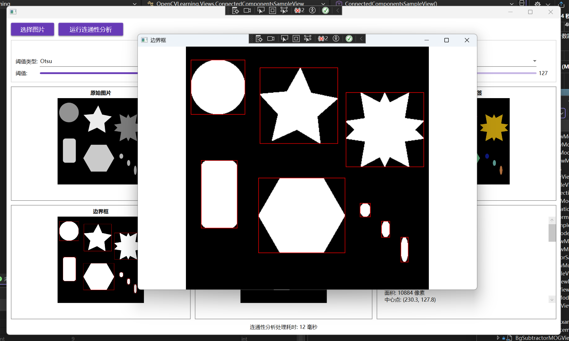
创建边界框图像:
// 创建边界框图像
using var rectView = binary.CvtColor(ColorConversionCodes.GRAY2BGR);
foreach (var blob in cc.Blobs.Skip(1))
{
    rectView.Rectangle(blob.Rect, Scalar.Red);
}
获取最大连通区域:
// 获取最大连通区域
var maxBlob = cc.GetLargestBlob();
using var filtered = new Mat();
cc.FilterByBlob(src, filtered, maxBlob);
增加点击显示大图功能
为了更好查看效果,可以增加一个点击显示大图功能,如下所示:
1、XAML中的样式定义
在 ConnectedComponentsSampleView.xaml 中定义了一个可点击图片的样式:
<Style x:Key="ClickableImageStyle" TargetType="Image">
    <Setter Property="Cursor" Value="Hand"/>
    <EventSetter Event="MouseLeftButtonDown" Handler="Image_MouseLeftButtonDown"/>
</Style>
这个样式做了两件事:
将鼠标悬停时的光标设置为手型,提示用户可以点击
为 MouseLeftButtonDown 事件绑定处理函数 Image_MouseLeftButtonDown
2、图片控件应用样式
所有需要点击查看大图的图片控件都应用了这个样式,例如:
<Image Source="{Binding OriginalImage}" Stretch="Uniform" Height="200"
       Visibility="{Binding HasImage, Converter={StaticResource BooleanToVisibilityConverter}}"
       Style="{StaticResource ClickableImageStyle}"
       Tag="原始图片"/>
注意这里使用了 Tag 属性来存储图片的标题,用于后续显示大图时的窗口标题。
3、事件处理逻辑
在 ConnectedComponentsSampleView.xaml.cs 中实现了核心的事件处理逻辑:
private void Image_MouseLeftButtonDown(object sender, MouseButtonEventArgs e)
{
    if (sender is Image image && image.Source is BitmapImage bitmapImage)
    {
        // 获取图片标题
        string title = image.Tag as string ?? "图片";

        // 创建新窗口显示大图
        Window imageWindow = new Window
        {
            Title = title,
            Width = 800,
            Height = 600,
            WindowStartupLocation = WindowStartupLocation.CenterScreen,
            WindowState = WindowState.Normal
        };

        // 创建Image控件显示图片
        var largeImage = new Image
        {
            Source = bitmapImage,
            Stretch = Stretch.Uniform // 保持原始比例
        };

        // 设置窗口内容
        imageWindow.Content = largeImage;

        // 显示窗口
        imageWindow.Show();
    }
}

 浙公网安备 33010602011771号