
DMVPN
实验拓扑及网段规划:
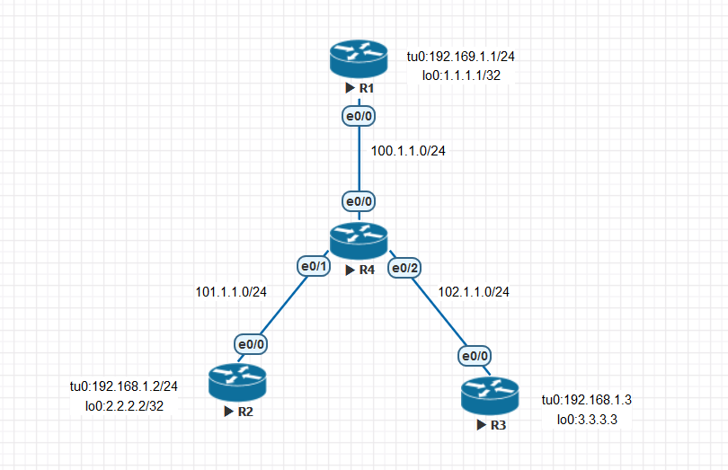
说明:R1为hub路由器,R2,R3为spoke路由器,R4为ISP
首先确保出口路由器R1,R2,R3的公网地址口e0/0互通,运行一个ospf 1 ,实际组网中不需要做此步骤,为ISP的活
R1,R2,R3,R4 ospf 配置
R1#sh run | s r o
router ospf 1
router-id 1.1.1.1
network 100.1.1.1 0.0.0.0 area 0
R2#sh run | s r o
router ospf 1
router-id 2.2.2.2
network 101.1.1.1 0.0.0.0 area 0
R3#sh run | s r o
router ospf 1
router-id 3.3.3.3
network 102.1.1.1 0.0.0.0 area 0
R4#sh run | s r o
router ospf 1
router-id 4.4.4.4
network 100.1.1.2 0.0.0.0 area 0
network 101.1.1.2 0.0.0.0 area 0
network 102.1.1.2 0.0.0.0 area 0
这样R1,R2,R3的公网口就可以互通了,这是做GRE的基础(必须保证)
R1#ping 101.1.1.1
Type escape sequence to abort.
Sending 5, 100-byte ICMP Echos to 101.1.1.1, timeout is 2 seconds:
!!!!!
R1#ping 102.1.1.1
Type escape sequence to abort.
Sending 5, 100-byte ICMP Echos to 102.1.1.1, timeout is 2 seconds:
!!!!!
MGRE配置:
R1(Hub端)
interface Tunnel0
ip address 192.168.1.1 255.255.255.0
tunnel source 100.1.1.1
tunnel mode gre multipoint(模式为多点GRE)
NHRP配置:
ip nhrp map multicast dynamic
ip nhrp network-id 12345
ip nhrp redirect
R2,R3(Spoke端)
MGRE配置
interface Tunnel0
ip address 192.168.1.2/3 255.255.255.0(2为R2tu0口,3为R3tu0口地址)
tunnel source Ethernet0/0
tunnel mode gre multipoint
NHRP配置
ip nhrp map multicast 100.1.1.1
ip nhrp map 192.168.1.1 100.1.1.1
ip nhrp network-id 12345
ip nhrp nhs 192.168.1.1
配置完上述,GRE隧道建立完成,R1,R2,R3的tu0口地址可以相互通信,相当于逻辑直连,这为建立动态路由协议建立了基础。
这里我们抓包看下数据包封装情况:
在R1的e0/0口抓包,用R1去ping R2的tu0口192.168.1.2地址
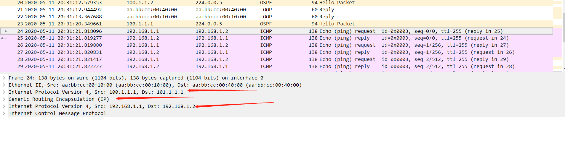
外层封装为公网的ip地址,Src:100.1.1.1,Dst:101.1.1.1
往里是一个GRE包头,
内层是一个私网的ipv4包头:Src:102.168.1.1 ,Des:192.168.1.2
因为R1,R2,R3的隧道口逻辑直连,这样就可以运行一个动态路由协议将,R1,R2,R3的身后路由条目学习到
运行一个eigrp 1
R1#sh run | s r e
router eigrp 1
network 1.1.1.1 0.0.0.0
network 192.168.1.1 0.0.0.0
R2#sh run | s r e
router eigrp 1
network 2.2.2.2 0.0.0.0
network 192.168.1.2 0.0.0.0
R3#sh run | s r e
router eigrp 1
network 3.3.3.3 0.0.0.0
network 192.168.1.3 0.0.0.0
因为水平分割特性R2,R3的路由条目不能通过R1学习到,在R1上关闭水平分割特性
interface Tunnel0
no ip split-horizon eigrp 1
这样就可以学习到对方的路由条目了
R2#sh ip route

D 1.1.1.1 [90/27008000] via 192.168.1.1, 00:00:01, Tunnel0
2.0.0.0/32 is subnetted, 1 subnets
C 2.2.2.2 is directly connected, Loopback0
3.0.0.0/32 is subnetted, 1 subnets
D 3.3.3.3 [90/28288000] via 192.168.1.1, 00:00:01, Tunnel0
100.0.0.0/24 is subnetted, 1 subnets
O 100.1.1.0 [110/20] via 101.1.1.2, 00:00:01, Ethernet0/0
101.0.0.0/8 is variably subnetted, 2 subnets, 2 masks
C 101.1.1.0/24 is directly connected, Ethernet0/0
L 101.1.1.1/32 is directly connected, Ethernet0/0
102.0.0.0/24 is subnetted, 1 subnets
O 102.1.1.0 [110/20] via 101.1.1.2, 00:00:01, Ethernet0/0
192.168.1.0/24 is variably subnetted, 2 subnets, 2 masks
C 192.168.1.0/24 is directly connected, Tunnel0
L 192.168.1.2/32 is directly connected, Tunnel0
由于R2,R3之间通信会通过R1(Hub),产生次优路径
优化配置:
R1:
interface Tunnel0
ip nhrp redirect
R2,R3:
interface Tunnel0
ip nhrp shortcut
如果上述学习身后路由的动态路由协议换成OSPF,注意将接口的网络类型改为P2MP
上述优化完成后:
R2#ping 3.3.3.3 source 2.2.2.2
Type escape sequence to abort.
Sending 5, 100-byte ICMP Echos to 3.3.3.3, timeout is 2 seconds:
Packet sent with a source address of 2.2.2.2
!!!!!
R2到R3直接一跳过去,不再经过R1(Hub端)
R2#traceroute 3.3.3.3 source 2.2.2.2
Type escape sequence to abort.
Tracing the route to 3.3.3.3
VRF info: (vrf in name/id, vrf out name/id)
1 192.168.1.3 1 msec 1 msec *

 浙公网安备 33010602011771号