

CCIE PROFESSION DAVELOPMENT VOLUME I : A detailed examination of interior routing protocols
 Reading notes of lt;
CCIE PROFESSION DAVELOPMENT VOLUME I : A detailed examination of interior routing protocols
Introduction
Objectives
This book's objective is to make CCIES,not to make people who can pass the CCIE lab.
Audience
The beginners,the intermediate-level networking professinal and highly exsperiend networking expert are all suitable to read this book.
Organizations
The foureen charpters of the book are divided into three parts.
Part I(chaopter one to chaopter four) examine the basic of networks and routing.
Part II(charpter five to charpter ten) covers the TCP/IP Interior Gateway Protocols.
Part III(charpter eleven to charpter fourteen) examines the tools avaliable for creating and managing interoperability with multiple routing protocols,as well as such tools as default routers and router filtering.
Foreword
Due to different traffic patterns and the equality of serice required by each type of information,solid hands-on experience is imperative for managing,desiging,and troubleshooting these networks.
The author highly recommends that you use these books as a hands-on learning tool by duplicating the examples and case studies using Cisco producys.
Part I Routing Basics
Charpter 1 Basic Concepts:Internetworks,Routers,and Address
Bicycles with Motors
A LAN is like a bike with a motor,and we don't make Mopeds!
Physically, a LAN accomplishes resource pooling among a group of devices by connecting them to a common, shared medium, or date link.
The MAC(Medium Access Control) , as the name implies, dictates how each machine will access and share a given medium.
So far, a LAN has been defined as bing a cummunity of devices such as PCs, printers, and servers coexisting on a commun communications medium and following a common protocol that regulates how they access the medium.
Data Link Address
Because two individuals cannot be uniquely identified, date is occasionally deliverd incorrectly and a process must be implemented to correct the error.
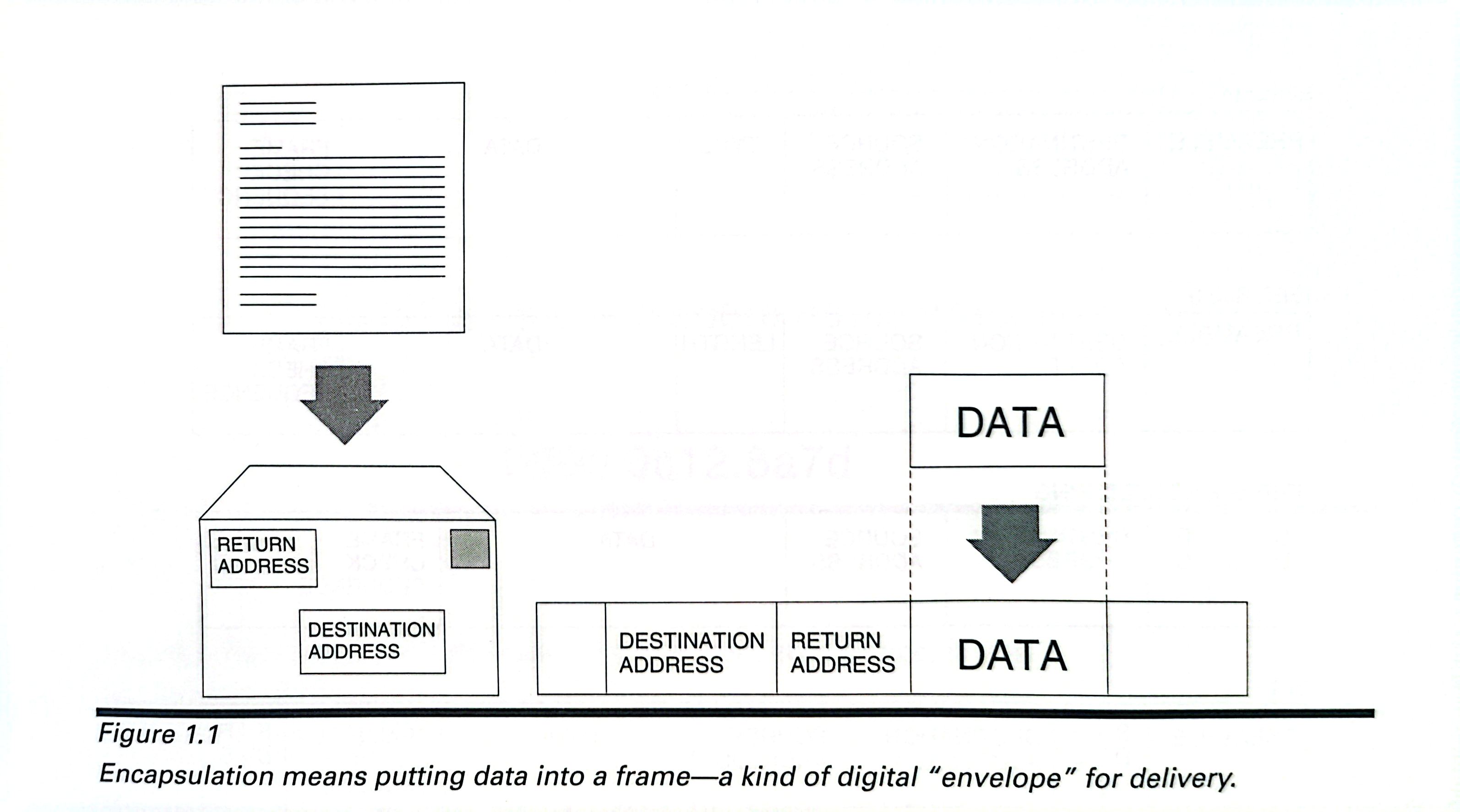
When data is delievered on a LAN, it is encapsulated with an entity called frame, a kind of binary envelop. Think of data encapsulation as being the digital equivalent of placing a letter inside an envolep. A destination address and a return(source) address are written on the outside of the envelop.
The format of the address depends on the particular MAC protocol, but all the addresses serve the same purpose: to uniquely idendify the machine for which the frame is destined and the device from which it was sent.
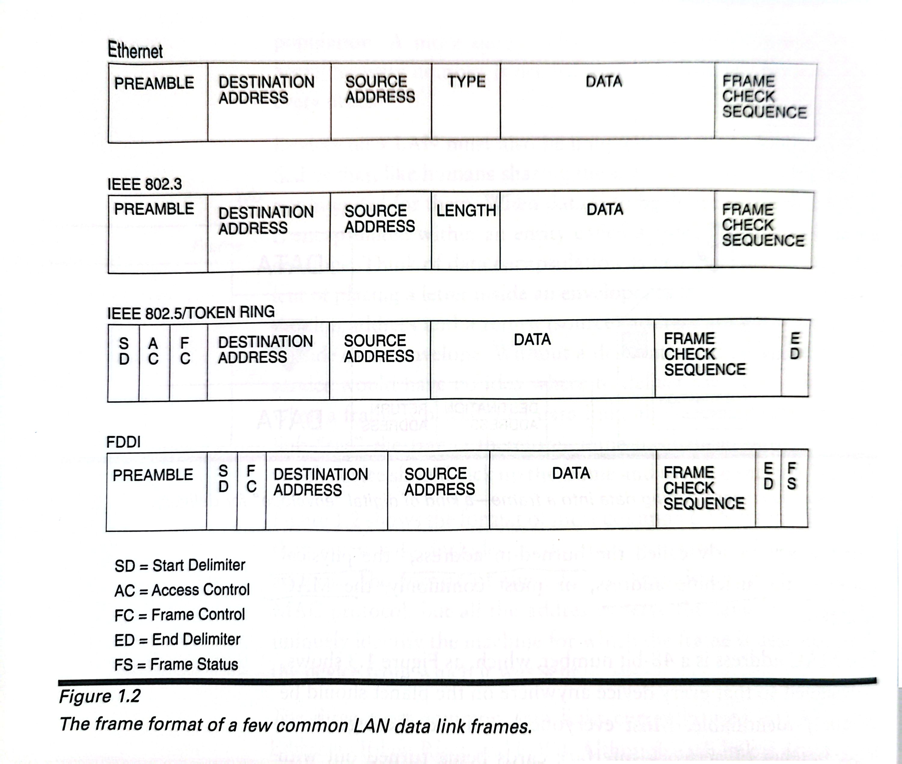
Although each link is drastically different from the others, they share a common format for addressing devices on the network. This format is variouslly called the brund-in address, the physical address, the machine address, or most commonly, the MAC address.
The MAC addresss is a 48-bit number, which, as Figure 1.3 shows, is designed so that every device anywhere on the planet shoud be uniquely identifiable.
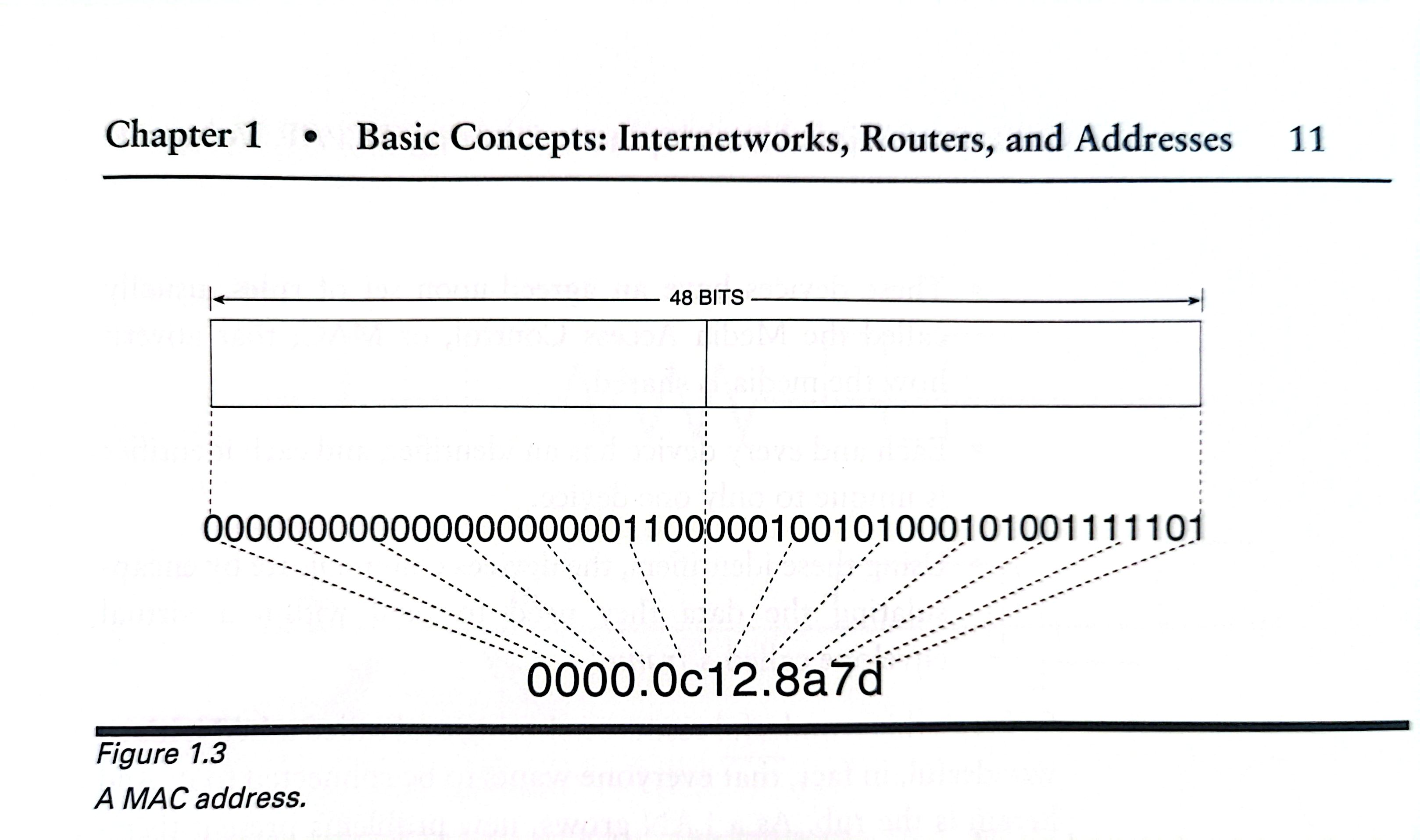
Although the MAC address are by convention referred to as "address",they are really name, which means it is a part of that device and goes wherever the device goes.
The information presented so far may be distilled into a few brief statements:
A date link communication network is a group of two or more devices connected by a common, shared medium.
These devices have a agreed-upon set of rules, usually called the Media Access Control, or MAC, that govern how the media is shared.
Each and every device has an identifier, and each identifier is unique to only one device.
Using these identifiers, the devices communicates by encapsulating the data they need to send with a virtual envelop called frame.
Repeaters and Bridges
As a LAN grows, new problems present themselves.
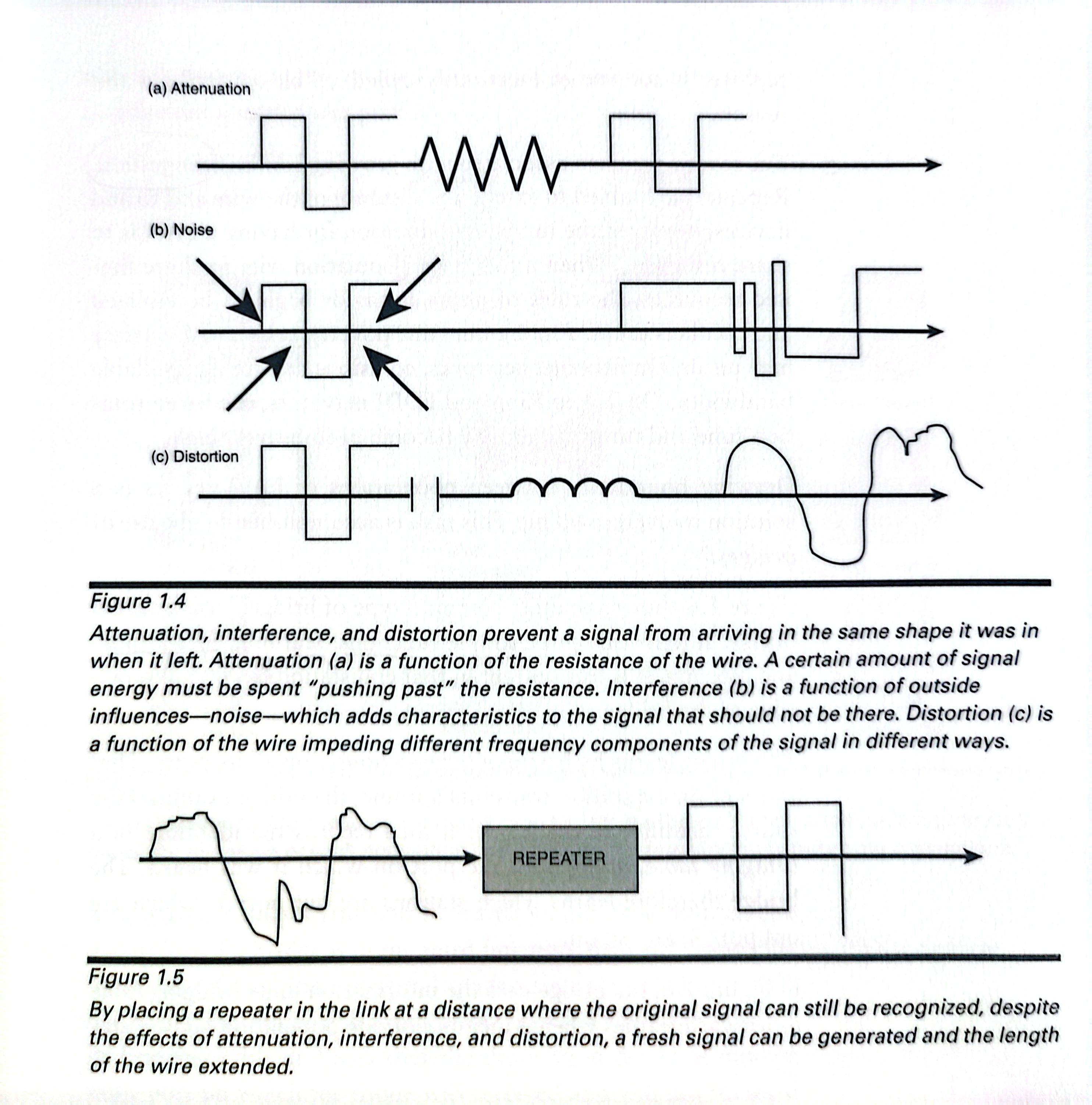
The first problem is one of the physical distance.
Repeaters are added to the wire at certain intervals to alleviate the difficulties associated with excesssive distance. A repeater is placed on the media some distance from the signal source but still near enough to be correctly interpret the signal(see Figure 1.5). It then repeats the signal by producing a new, clean copy of the old degraded signal.
The second problem associated with growing LAN is congestion.
Drawing boundaries between polulations of LAN devices is a solution to overcrowding. This task is accomplished by the use of bridge.
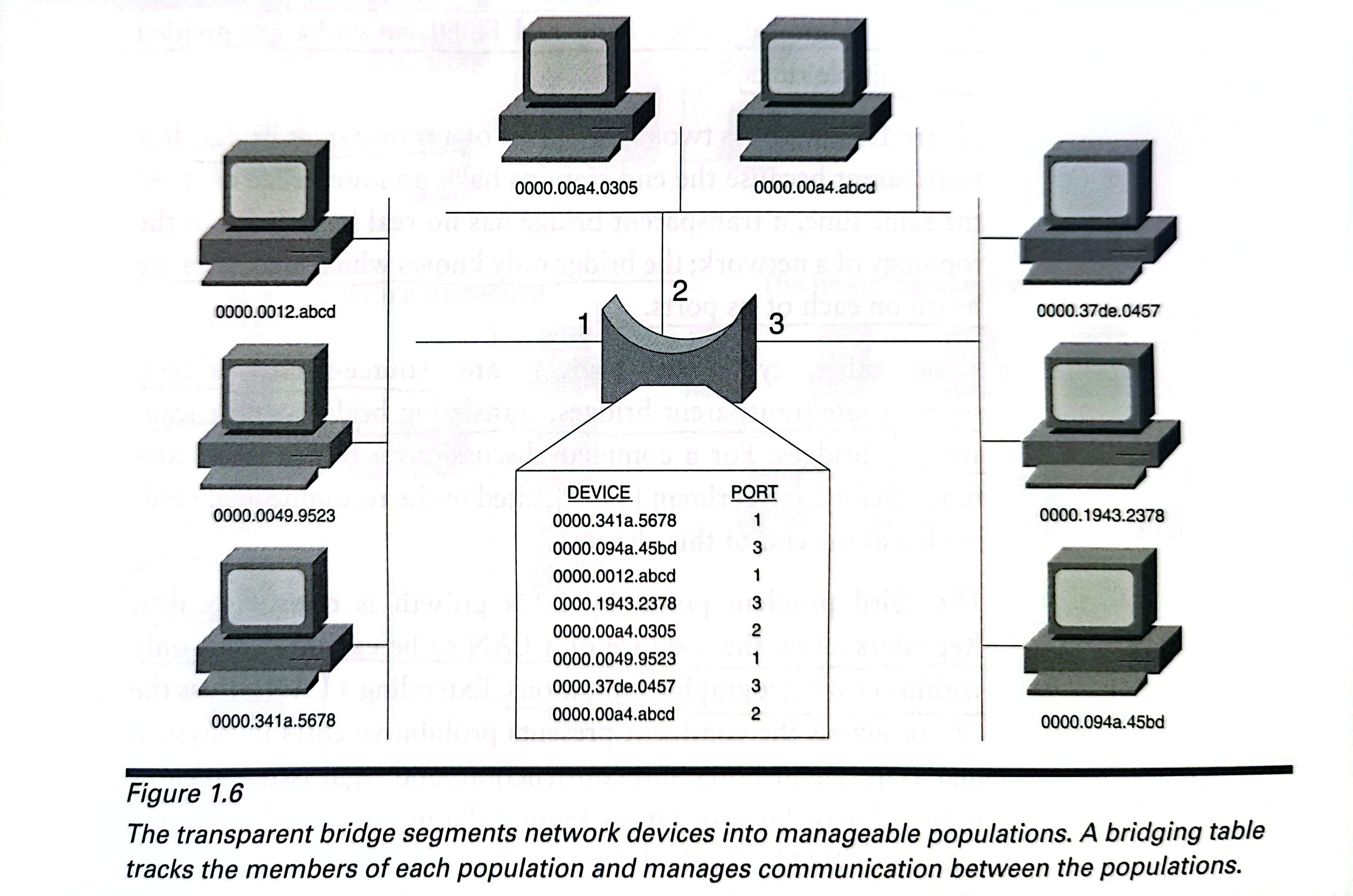
It performs three simple functions: learning, forwarding, and filtering.
The bridge learns by listening promiscuously on all its ports.That is, every time a station transmits a frame, the bridge examines the source identifier of the frame. It then records the identifier in a bridging table, along with the port on which is was heard. The bridge therefore learns which stations are out port 1, which are out port 2, and so on.
The bridge uses the information in its bridging table to forward frames when a member of one polulation——say, a station out port 1——wants to send a frame to member of another population: a station out port 2.
IF a station out port 2 sends a frame to another station out port 2, the bridge will examine the frame. The bridge consults its bridging table and sees that the destination device is out the same port on which the frame was received and will not forward the frame. The frame is filtered.
Filtering means that only frames that need to be forwarded to another polupation will be, and resources are conserved. Ethernet networks are divided into collision domains.
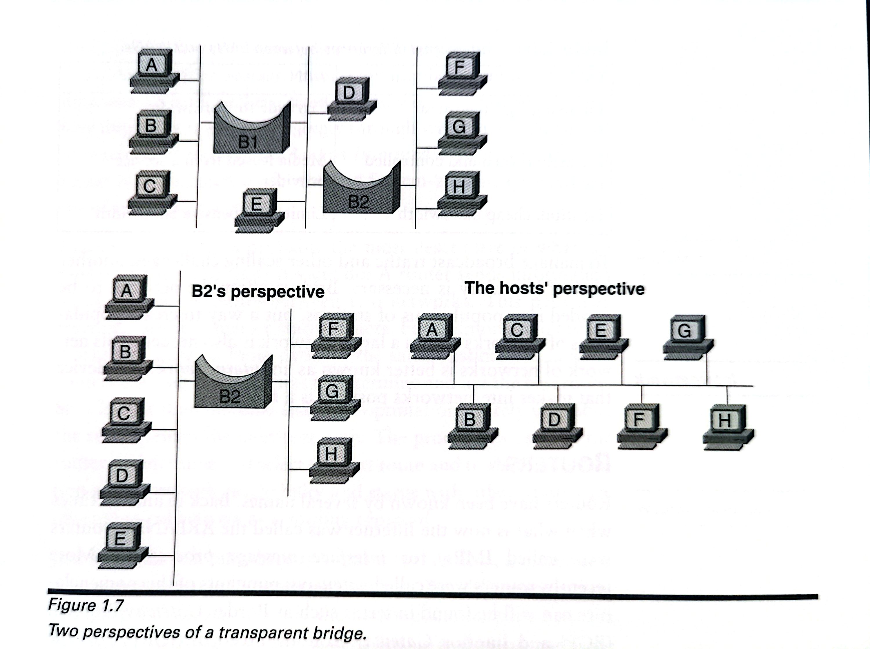
Fifure 1.7 illustrates two perspectives of a transparent bridge.It is transparent because the end stations have no knowledge of it.
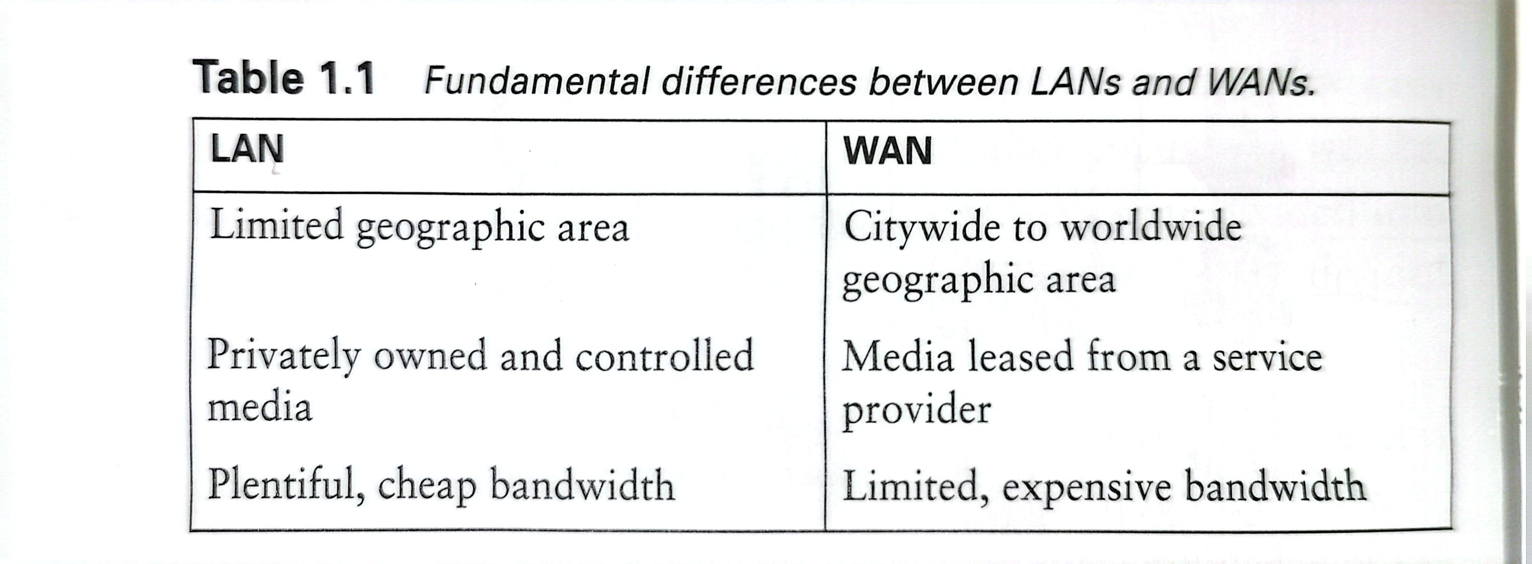
The third problem posed by LAN growth is one of locality.
Extending a LAN across the city presents prohibitive costs in physical materials, engineering and construction,and legal issues such as right-of-way. Such distances require the use of a wide-area network, or WAN.
A fourth problem is one of scalability.
As a bridged network becomes larger and larger, more and more stations will be originating broadcast traffic, soon, broadcast frames cause the network to become congested again.
To manage broadcast traffic and other scaling chanllenges, another kind of boundry is necesary.Bridges allow the network to be divided into polulations of station, but a way to create populations of networks with a larger network is alse needed. This network of network is better known as an internetwork.The device that makes internetwork possible is a router.
Routers
Routers have been known by several names, such as IMPs(interface message processors), gateways and Intermediate Systems(IS).
Interface message processors: a router swtiches date messages, or packets, from one network to another.
Gateway: a router is a gateway through which data can be sent to reach another network.
Intermediate System: a router is an intermediary for the End System-to-End System delivery of internetwork data.
A router sends information along a route——a path——between two networks.In internetworks that have multiple paths to the same destination, modern routers use a set of procedures to determine and use the best route.The procedures used by the routersto determine and select best route and to share information about network reachability and status with other routers are referred to collectively as a routing protocol.
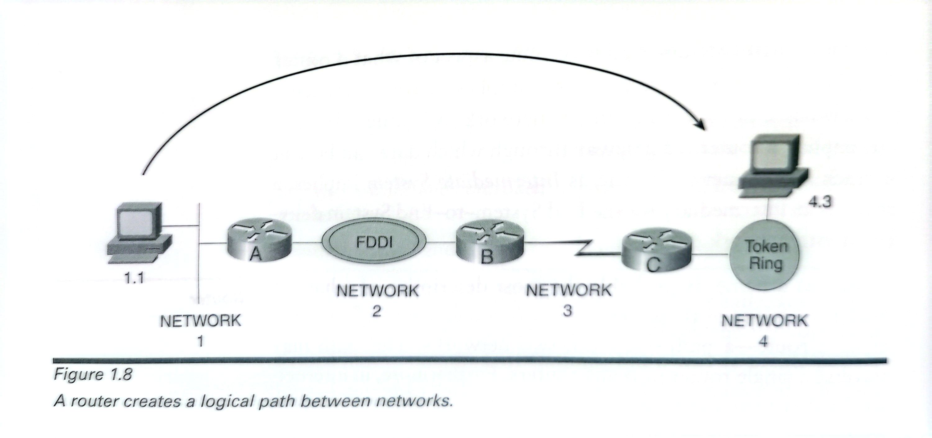
Just as a data link may directly connect devices, a router alse creates a connection between two devices.The difference is that it is a logical path.
To be delivered across the logical path of a routed internetwork, data must also be encapsulated; the digital envelope used by routers is a packet.
The packet remains the same from end to end:
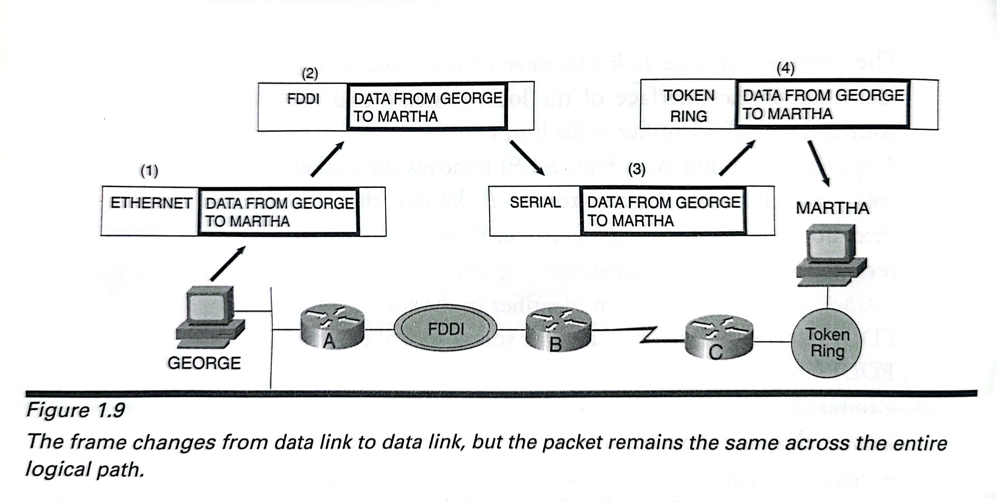
1.The originating host encapsulates the data to be lelivered within a packet.The packet must then be delivered across the host's data link to the local router that host's default gateway——so the host encapsulates the packet within a frame.This operation is the same as placing an envelope inside of a larger envelope,for example,inserting an envelope containing a letter into a Federal Express envelope. The destination data link identifier of the frame is theidentifier of the interface of the local router,and the source data link identifier is the host's.
2.That router(router A in Figure1.9)removes the packetfrom the Ethernet frame;router A knows that thenext-hop router on the path is router B,out is FDDI interface,so router A encapsulates the packet in an FDDIframe.Now the destination identifier in the frame is theFDDI interface of router B,and the source identifier is the FDDI interface of router A.
3.Router B removes the packet from the FDDI frame,knows that the next-hop router on the path is router Cacross the serial link,and sends the packet to C encapsu-lated in the proper frame for the serial link.
4.Router C removes the packet and recognizes that the sta-tion for which the packet is destined is on its directly con-nected Token Ring network;C encapsulates the packet in a Token Ring frame with the destination identifier of thedestination station and the source identifier of its TokenRing interface.The packet has been delivered.
The key to understanding this entire process is to notice that the frames and their related data link identifiers, which have relevance only for each individual network, change for each network the packet traverses. The packet remains the same form end to end.
Network Addresses
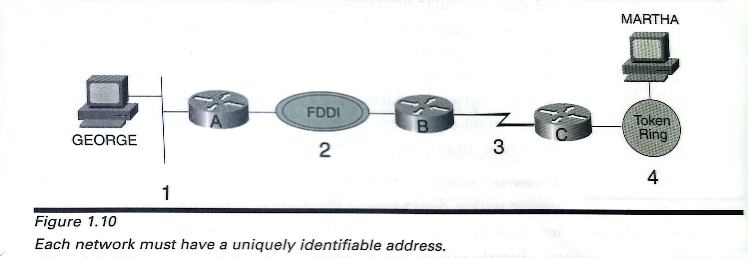
Each member network in a routed internetwork requires a unique idendifier: network address.
Figure 1.10 suggests a type of network address. Notich that every network has its own unique address.
Let's back in Figure 1.9:
How did the originating host know that the packet needed to be belivered to its gateway for routing?And how did the routers know where to send the packet?
The routers can deliver the packet because the originating host put a destination address in the packet.From the perspective of the router,the destination address is all that isneeded.As a rule,all routers really care about is the location of each network.Individual devices are not relevant to the router;the router only needs to deliver the packet to the correct destinationnetwork.When the packet arrives at the network,the data link identifier can be used to deliver the data to the individual device on the network.
The purpose of a router is to deliver packets to the proper destination networks. As such, the only individual devices router typically care about are other routers.
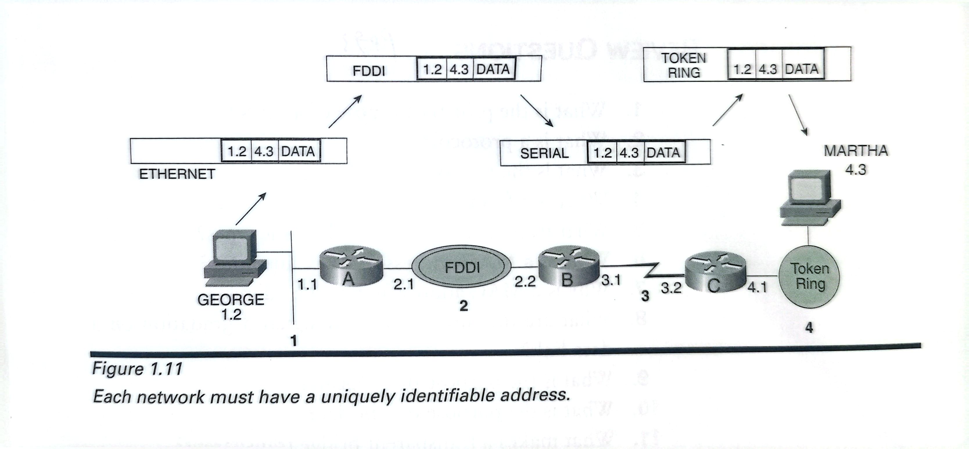
The network address must have both a network identifier and a host identifier(Figure 1.11)
When the routers sees that the destination address of a packet is one of its directly connected networks, how does the router know where to deliever the packet?
Likewise router C must be able to recognize,“I've received apacket with a destination address of 4.3.Because my Token Ring interface has an address of 4.1,I know that network4is one ofmy directly connected networks.As a member of that networkmyself,I know that station 4.3 has a MAC identifier of 0000.2354.AC6B;I'll just pop this packet into a Token Ringframe and deliver it.”
How did the originating host know that the packet needed to be delieverd to its default gateway for routing?
The origi-nating host must be able to recognize its own and others'network addresses,to say in effect:“I need to deliver this packet to device 4.3.My network address is1.2;therefore,I know that the desti-nation is on a different network than mine,and I'll need to sendthe packet to my local router for delivery.”
acnnewwork mosnave a umyuery emmaie auuress.
LOOKING AHEAD
This chapter has established that a network address must have both a network portion and a host portion and that some mechanism must exist for mapping a network address to a data link identifier.Chapter2,“TCP/IP Review,” shows how IP meets these requirements.It examines the IP address format,the method by which IP does network-to-data link mappings,and a few other mechanisms important to the IP routing process.

 浙公网安备 33010602011771号