L/RVDT、Resolver相关技术
名词解释
LVDT,Linear variable differential transformer,线性可变差动变压器
RVDT,Rotary variable differential transformer,旋转可变差动变压器
Resolver,旋转变压器
主要参考:
[1] 李稷, 李玲, 张辉, 等. LVDT传感器仿真电路的设计与研究[J/OL]. 仪表技术, 2011(9): 67-70. DOI:10.19432/j.cnki.issn1006-2394.2011.09.022.
[2] 李稷. RVDT传感器仿真电路的设计与研究[J/OL]. 民用飞机设计与研究, 2011(2): 56-59. DOI:10.19416/j.cnki.1674-9804.2011.02.015.
不得不说:
网络上关于LVDT、RVDT的资料比较少,笔者确实从这两篇论文中学到了一些东西。但是,这两论文的内容除了L与R不同,其理论、电路和结果等几乎完全一样,这不禁让人质疑其内容的科学性。因此,笔者仅引用了RVDT部分内容,且必须谨慎地提醒读者,以下内容,仅供参考。当笔者读到更科学的资料后,也会更新此文章。
LVDT
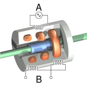
Cutaway view of an LVDT. Current is driven through the primary coil at A, causing an induction current to be generated through the secondary coils at B.
LVDT 的剖视图。电流驱动通过 A 处的初级线圈,从而通过 B 处的次级线圈产生感应电流。
LVDTs are robust, absolute linear position/displacement transducers; inherently frictionless, they have a virtually infinite cycle life when properly used. As AC operated LVDTs do not contain any electronics, they can be designed to operate at cryogenic temperatures or up to 1200 °F (650 °C), in harsh environments, and under high vibration and shock levels. LVDTs have been widely used in applications such as power turbines, hydraulics, automation, aircraft, satellites, nuclear reactors, and many others. These transducers have low hysteresis and excellent repeatability.
LVDT 是坚固耐用的绝对线性位置/位移传感器;它们本质上是无摩擦的,如果使用得当,它们的循环寿命几乎是无限的。由于交流供电的 LVDT 不包含任何电子器件,因此它们可以设计为在低温或高达 1200 °F (650 °C) 的恶劣环境以及高振动和冲击水平下运行。 LVDT 已广泛应用于动力涡轮机、液压、自动化、飞机、卫星、核反应堆等领域。这些传感器具有低磁滞和出色的重复性。
The LVDT converts a position or linear displacement from a mechanical reference (zero or null position) into a proportional electrical signal containing phase (for direction) and amplitude (for distance) information. The LVDT operation does not require an electrical contact between the moving part (probe or core assembly) and the coil assembly, but instead relies on electromagnetic coupling.
LVDT 将机械参考(零位置或零位置)的位置或线性位移转换为包含相位(用于方向)和幅度(用于距离)信息的比例电信号。 LVDT 操作不需要移动部件(探头或磁芯组件)与线圈组件之间存在电接触,而是依赖于电磁耦合。
The linear variable differential transformer has three solenoidal coils placed end-to-end around a tube. The center coil is the primary, and the two outer coils are the top and bottom secondaries. A cylindrical ferromagnetic core, attached to the object whose position is to be measured, slides along the axis of the tube. An alternating current drives the primary and causes a voltage to be induced in each secondary proportional to the length of the core linking to the secondary.[3] The frequency is usually in the range 1 to 10 kHz.
线性可变差动变压器具有三个首尾相连围绕管放置的螺线管线圈。中心线圈是初级线圈,两个外部线圈是顶部和底部次级线圈。圆柱形铁磁芯附在要测量位置的物体上,沿管轴滑动。交流电驱动初级线圈,并在每个次级线圈中感应出与连接次级线圈的磁芯长度成比例的电压。 [3] 频率通常在 1 至 10 kHz 范围内。
As the core moves, the primary's linkage to the two secondary coils changes and causes the induced voltages to change. The coils are connected so that the output voltage is the difference (hence "differential") between the top secondary voltage and the bottom secondary voltage. When the core is in its central position, equidistant between the two secondaries, equal voltages are induced in the two secondary coils, but the two signals cancel, so the output voltage is theoretically zero. In practice minor variations in the way in which the primary is coupled to each secondary means that a small voltage is output when the core is central.
当磁芯移动时,初级线圈与两个次级线圈的连接发生变化,导致感应电压发生变化。线圈的连接使得输出电压是顶部次级电压和底部次级电压之间的差(因此“差值”)。当磁芯位于其中心位置时,两个次级线圈之间等距,两个次级线圈中感应出相等的电压,但两个信号相互抵消,因此理论上输出电压为零。实际上,初级与每个次级的耦合方式的微小变化意味着当磁芯位于中心时会输出小电压。
This small residual voltage is due to phase shift and is often called quadrature error. It is a nuisance in closed loop control systems as it can result in oscillation about the null point, and may also be unacceptable in simple measurement applications. It is a consequence of using synchronous demodulation, with direct subtraction of the secondary voltages at AC. Modern systems, particularly those involving safety, require fault detection of the LVDT, and the normal method is to demodulate each secondary separately, using precision half wave or full wave rectifiers, based on op-amps, and compute the difference by subtracting the DC signals. Because, for constant excitation voltage, the sum of the two secondary voltages is almost constant throughout the operating stroke of the LVDT, its value remains within a small window and can be monitored such that any internal failures of the LVDT will cause the sum voltage to deviate from its limits and be rapidly detected, causing a fault to be indicated. There is no quadrature error with this scheme, and the position-dependent difference voltage passes smoothly through zero at the null point.
这个小的残余电压是由相移引起的,通常称为正交误差。这在闭环控制系统中是一个麻烦,因为它可能导致零点附近的振荡,并且在简单的测量应用中也可能是不可接受的。这是使用同步解调的结果,直接减去交流次级电压。现代系统,特别是涉及安全的系统,需要对 LVDT 进行故障检测,通常的方法是使用基于运算放大器的精密半波或全波整流器单独解调每个次级,并通过减去直流信号来计算差值。因为,对于恒定激励电压,两个次级电压之和在 LVDT 的整个工作行程中几乎恒定,因此其值保持在一个小窗口内,并且可以进行监控,以便 LVDT 的任何内部故障都会导致电压和偏离其极限并被快速检测到,从而导致故障被指示。该方案不存在正交误差,并且位置相关的差分电压在零点平滑地通过零。
Where digital processing in the form of a microprocessor or FPGA is available in the system, it is customary for the processing device to carry out the fault detection, and possibly ratiometric[4] processing to improve accuracy, by dividing the difference in secondary voltages by the sum of the secondary voltages, to make the measurement independent of the exact amplitude of the excitation signal. If sufficient digital processing capacity is available, it is becoming commonplace to use this to generate the sinusoidal excitation via a DAC and possibly also perform the secondary demodulation via a multiplexed ADC.
当系统中可以使用微处理器或 FPGA 形式的数字处理时,处理设备通常会执行故障检测,并可能进行比例 [4] 处理,以通过除以差值来提高精度次级电压除以次级电压之和,以使测量独立于激励信号的精确幅度。如果有足够的数字处理能力,则使用它通过 DAC 生成正弦激励并可能还通过多路复用 ADC 执行二次解调已变得司空见惯。
When the core is displaced toward the top, the voltage in top secondary coil increases as the voltage in the bottom decreases. The resulting output voltage increases from zero. This voltage is in phase with the primary voltage. When the core moves in the other direction, the output voltage also increases from zero, but its phase is opposite to that of the primary. The phase of the output voltage determines the direction of the displacement (up or down) and amplitude indicates the amount of displacement. A synchronous detector can determine a signed output voltage that relates to the displacement.
当铁芯向顶部移动时,顶部次级线圈中的电压增加,而底部次级线圈中的电压减小。由此产生的输出电压从零开始增加。该电压与初级电压同相。当磁芯向另一个方向移动时,输出电压也从零开始增加,但其相位与初级相反。输出电压的相位决定了位移的方向(向上或向下),幅度表示位移量。同步检测器可以确定与位移相关的带符号的输出电压。
RVDT

A rotary variable differential transformer (RVDT) is a type of electrical transformer used for measuring angular displacement. The transformer has a rotor which can be turned by an external force. The transformer acts as an electromechanical transducer that outputs an alternating current (AC) voltage proportional to the angular displacement of its rotor shaft.
旋转可变差动变压器(RVDT)是一种用于测量角位移的电力变压器。变压器具有可通过外力转动的转子。变压器充当机电换能器,输出与其转子轴的角位移成比例的交流 (AC) 电压。
In operation, an alternating current (AC) voltage is applied to the transformer primary to energize the RVDT. When energized with a constant AC voltage, the transfer function (output voltage vs. shaft angular displacement) of any particular RVDT is linear (to within a specified tolerance) over a specified range of angular displacement.
在操作中,交流 (AC) 电压施加到变压器初级,为 RVDT 供电。当使用恒定交流电压通电时,任何特定 RVDT 的传递函数(输出电压与轴角位移)在指定的角位移范围内都是线性的(在指定的公差范围内)。
RVDTs employ contactless, electromagnetic coupling, which provides long life and reliable, repeatable position sensing with high resolution, even under extreme operating conditions. Most RVDTs consist of a wound, laminated stator and a salient two-pole rotor. The stator, containing four slots, contains both the primary winding and the two secondary windings, which may be connected together in some cases. RVDTs offer advantages such as sturdiness, relatively low cost, small size, and low sensitivity to temperature, primary voltage and frequency variations.
RVDT 采用非接触式电磁耦合,即使在极端工作条件下,也能提供长寿命和可靠、可重复的高分辨率位置传感。大多数 RVDT 由绕线叠片定子和凸极两极转子组成。包含四个槽的定子包含初级绕组和两个次级绕组,在某些情况下它们可以连接在一起。 RVDT 具有坚固、成本相对较低、尺寸小以及对温度、初级电压和频率变化不敏感等优点。
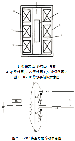
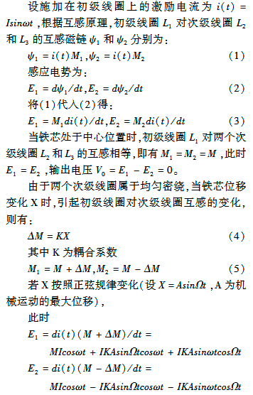
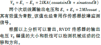
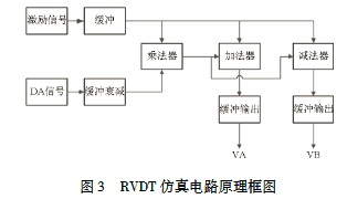
通过对RVDT传感器工作原理的分析可见RVDT输出的两路差动电压信号为位移信号(\(X(t)=Asin\Omega t\))和激励信号(\(i(t)=Isin\omega t\))的乘积的函数,当铁芯偏离中心位置时,两路输出信号的增量相位相反,因此来用乘法的方法模拟传感器输出的两路信号,其中利用DA模拟传感器的位移信号:RVDT仿真电路的原理框图如图3 所示。
信号解调
如前所述,VDT信号采集到两个次级线圈的输出电压\(E_1\)、\(E_2\)之后,需要求取\(E_1+E_2\)、\(E_1-E_2\)。这部分电路包含信号跟随、和差运算、同步解调、滤波电路四个部分。
首先通过信号跟随和和差运算电路后,得到和值(SUM)和差值(DIFF)及各自的反相信号。然后,VDT信号经过同步解调开关(可用MAX333芯片),将交流模拟量的负半幅值去掉。最后,经过滤波电路,成为直流模拟量,由AD转换电路采集。
采集得到\(E_1+E_2\)、\(E_1-E_2\)后,再根据具体机械结构,计算实际的角位移量。进而,使其服务于控制律计算。
Resolver
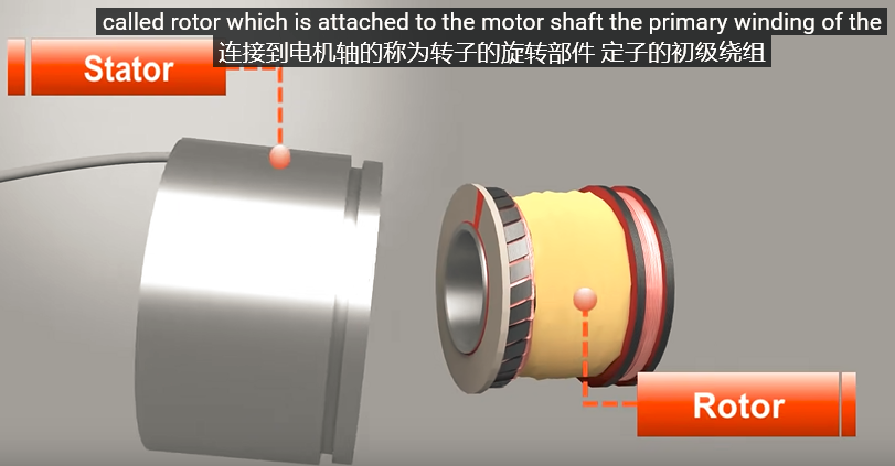
转子(Rotor)作为初级线圈,而定子(Stator)中有两个次级线圈
起始位置:
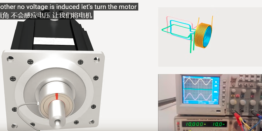
旋转90°:
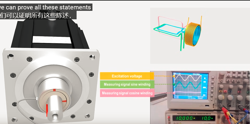
高速旋转下:
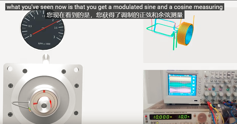
此时,将获得调制后的正余弦波形。

 浙公网安备 33010602011771号