实验1:SDN拓扑实践
一、实验目的
-
能够使用源码安装Mininet;
-
能够使用Mininet的可视化工具生成拓扑;
-
能够使用Mininet的命令行生成特定拓扑;
-
能够使用Mininet交互界面管理SDN拓扑;
-
能够使用Python脚本构建SDN拓扑。
二、实验环境
Ubuntu 20.04 Desktop amd64
三、实验要求
(一)基本要求
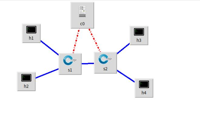
1.使用Mininet可视化工具,生成下图所示的拓扑,并保存拓扑文件名为学号.p
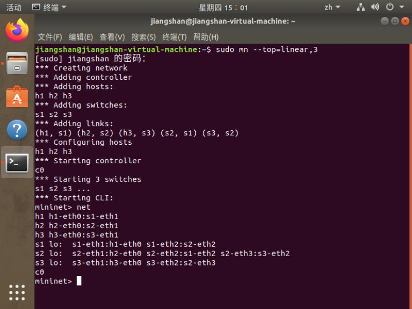
2.使用Mininet的命令行生成如下拓扑: a) 3台交换机,每个交换机连接1台主机,3台交换机连接成一条线。
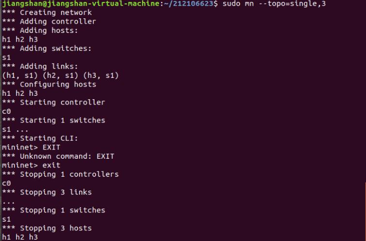
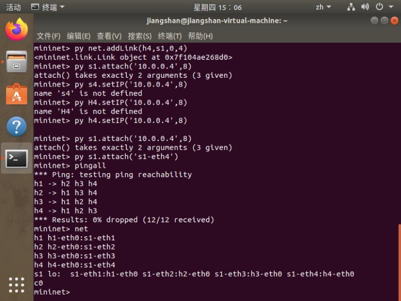
b) 3台主机,每个主机都连接到同1台交换机上。
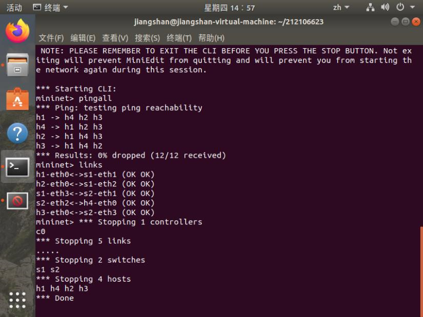
3.在2 b)的基础上,在Mininet交互界面上新增1台主机并且连接到交换机上,再测试新拓扑的连通性。
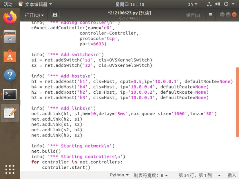
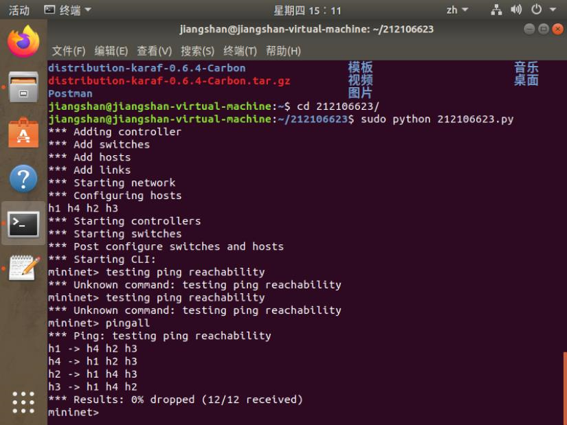
4.编辑基本要求第1步保存的Python脚本,添加如下网络性能限制,生成拓扑: a) h1的cpu最高不超过50%; b) h1和s1之间的链路带宽为10,延迟为5ms,最大队列大小为1000,损耗率50。
修改过的代码
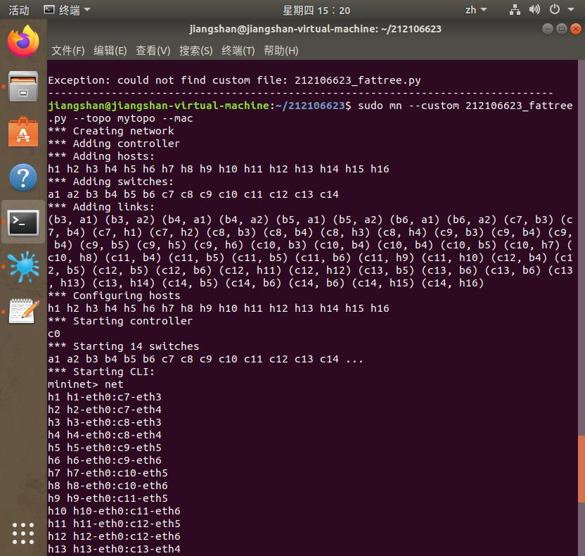
(二)进阶要求
#!/usr/bin/python

"""Custom topology example

Adding the 'topos' dict with a key/value pair to generate our newly defined

topology enables one to pass in '--topo=mytopo' from the command line.

"""
from mininet.topo import Topo
from mininet.net import Mininet
from mininet.node import RemoteController,CPULimitedHost
from mininet.link import TCLink
from mininet.util import dumpNodeConnections


class MyTopo( Topo ):
     "Simple topology example."
     def __init__( self ):
         "Create custom topo."
         # Initialize topology
         Topo.__init__( self )
         L1 = 2
         L2 = L1 * 2
         L3 = L2 * 2
         a = []
         b = []
         c = []
         # add core ovs

         for i in range( L1 ):

                 sw = self.addSwitch( 'a{}'.format( i + 1 ) )

                 a.append( sw )
         # add aggregation ovs
         for i in range( L2 ):
                 sw = self.addSwitch( 'b{}'.format( L1 + i + 1 ) )
                 b.append( sw )
         # add edge ovs
         for i in range( L3 ):
                 sw = self.addSwitch( 'c{}'.format( L1 + L2 + i + 1 ) )
                 c.append( sw )
         # add links between core and aggregation ovs
         for i in range( L1 ):
                 sw1 = a[i]
                 for sw2 in b[int(i/2)::int(L1/2)]:
                 # self.addLink(sw2, sw1, bw=10, delay='5ms', loss=10, max_queue_size=1000, use_htb=True)
                     self.addLink( sw2, sw1 )
         # add links between aggregation and edge ovs
         for i in range( L2 ):
                 for sw1 in b[i:i+2]:
                    for sw2 in c[i*2:(i+2)*2]:
                         self.addLink( sw2, sw1 )
         #add hosts and its links with edge ovs
         count = 1
         for sw1 in c:
                 for i in range(2):
                     host = self.
执行结果截图
四、个人总结

 浙公网安备 33010602011771号