【笔记】再笔记--边干边学Verilog HDL – 009
VGA驱动之一
实验环境
DE2 + Quartus II 9.1
目标
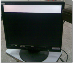
驱动VGA接口,在屏幕上显示一个白色的矩形。
设计
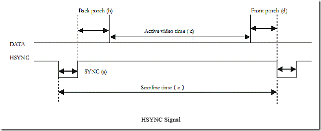
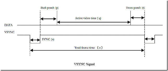
查阅VGA协议,搞定信号,主要是同步信号。本实验以800*600*60Hz为例。
1)同步信号
如上2图所示,分别用列同步和行同步来控制显示。各部分的参数如下表
1行=1056个点
1点= 25ns (怎么算的,查呗,或者1/60/628/1056 = 25.1ns)。
要注意的是,不是所有的点扫描都显示出来,只有在行,列同步信号的有效部分,才显示。即800*600.
2)至此,就可以把目标分成3个模块,第一个是驱动时钟25ns,可用pll得到,第二个是同步控制,用来产生合适的行、列同步信号,第三个是显示控制,即要显示什么东东。
3)代码
sync_module.v
 1 module sync_module
 2 (
 3     clk,rst_n,
 4     vsync,hsync,ready,
 5     column_addr,row_addr
 6 );
 7
 8     input clk;
 9     input rst_n;
10     output vsync;
11     output hsync;
12     output ready;
13     output [10:0] column_addr;
14     output [10:0] row_addr;
15
16     reg [10:0] count_h;
17
18     always @(posedge clk or negedge rst_n)
19         if(!rst_n)
20             count_h <= 11'd0;
21         else if (count_h == 11'd1056)
22             count_h <= 11'd0;
23         else
24             count_h <= count_h + 1'b1;
25
26     reg [10:0] count_v;
27
28     always @(posedge clk or negedge rst_n)
29         if(!rst_n)
30             count_v <= 11'd0;
31         else if(count_v == 11'd628)
32             count_v <= 11'd0;
33         else if(count_h == 11'd1056)
34             count_v <= count_v + 1'b1;
35
36     reg isready;
37
38     always @(posedge clk or negedge rst_n)
39         if (!rst_n)
40             isready <= 1'b0;
41         else if ((count_h > 11'd216 && count_h < 11'd1017) &&
42                 (count_v > 11'd27 && count_v < 11'd627))
43             isready <= 1'b1;
44         else
45             isready <= 1'b0;
46
47     assign vsync = (count_v <=11'd4) ? 1'b0: 1'b1;
48     assign hsync = (count_h <= 11'd128) ? 1'b0: 1'b1;
49     assign ready = isready;
50
51     assign column_addr = isready ? count_h - 11'd217 : 11'd0;
52     assign row_addr = isready ? count_v - 11'd28 : 11'd0;
53
54 endmodule
55
vga_control_module.v
 1 module vga_control_module
 2 (
 3     clk,rst_n,
 4     ready,column_addr,row_addr,
 5     red,green,blue
 6 );
 7
 8     input clk;
 9     input rst_n;
10     input ready;
11     input [10:0] column_addr;
12     input [10:0] row_addr;
13     output red;
14     output green;
15     output blue;
16
17     reg isrectangle;
18
19     always @(posedge clk or negedge rst_n)
20         if (!rst_n)
21             isrectangle <= 1'b0;
22         else if (column_addr > 11'd0 && row_addr < 11'd100)
23             isrectangle <= 1'b1;
24         else
25             isrectangle <= 1'b0;
26
27     assign red = ready && isrectangle ? 1'b1: 1'b0;
28     assign green = ready && isrectangle ? 1'b1 : 1'b0;
29     assign blue = ready && isrectangle ? 1'b1: 1'b0;
30
31 endmodule
vga_module.v
 1 module vga_module
 2 (
 3     CLOCK_50,KEY,    // clk,rst_n,
 4     VGA_CLK,        //40MHZ
 5     VGA_HS,VGA_VS,    //vsync,hsync,
 6     VGA_BLANK,    //ready
 7     VGA_SYNC,
 8     VGA_R,
 9     VGA_G,
10     VGA_B    //red,green,blue
11 );
12
13     input CLOCK_50; //clk;
14     input [0:0] KEY; //rst_n;
15     output VGA_CLK;
16     output VGA_HS;//vsync;
17     output VGA_VS;//hsync;
18     output VGA_BLANK;
19     output VGA_SYNC;
20     output [9:0] VGA_R; //red;
21     output [9:0] VGA_G; //green;
22     output [9:0] VGA_B; //blue;
23
24     assign VGA_SYNC = 1'b0;
25
26     pll_module U1
27     (
28         .inclk0(CLOCK_50),
29         .c0(VGA_CLK)
30     );
31
32     wire [10:0] column_addr;
33     wire [10:0] row_addr;
34
35     sync_module U2
36     (
37         .clk(VGA_CLK),
38         .rst_n(KEY[0]),
39         .vsync(VGA_VS),
40         .hsync(VGA_HS),
41         .column_addr(column_addr),
42         .row_addr(row_addr),
43         .ready(VGA_BLANK)
44     );
45
46   wire red,green,blue;
47   assign VGA_R = {10{red}},
48          VGA_G = {10{green}},
49          VGA_B = {10{blue}};
50
51     vga_control_module U3
52     (
53         .clk(VGA_CLK),
54         .rst_n(KEY[0]),
55         .ready(VGA_BLANK),
56         .column_addr(column_addr),
57         .row_addr(row_addr),
58         .red(red),
59         .green(green),
60         .blue(blue)
61     );
62
63 endmodule
64
65
66
4)综合后的模块图
实验结果
总结
才开始接触这些接口驱动的实验,不懂协议,有点无从下手。还是要把该查阅的基本理论搞清楚,再动手。另,DE2的VGA用到一个控制芯片,RGB每路都是10bit,和一般的参考教程不一样。先不管它,都当做一路给驱动。


 浙公网安备 33010602011771号