LEDC代码驱动
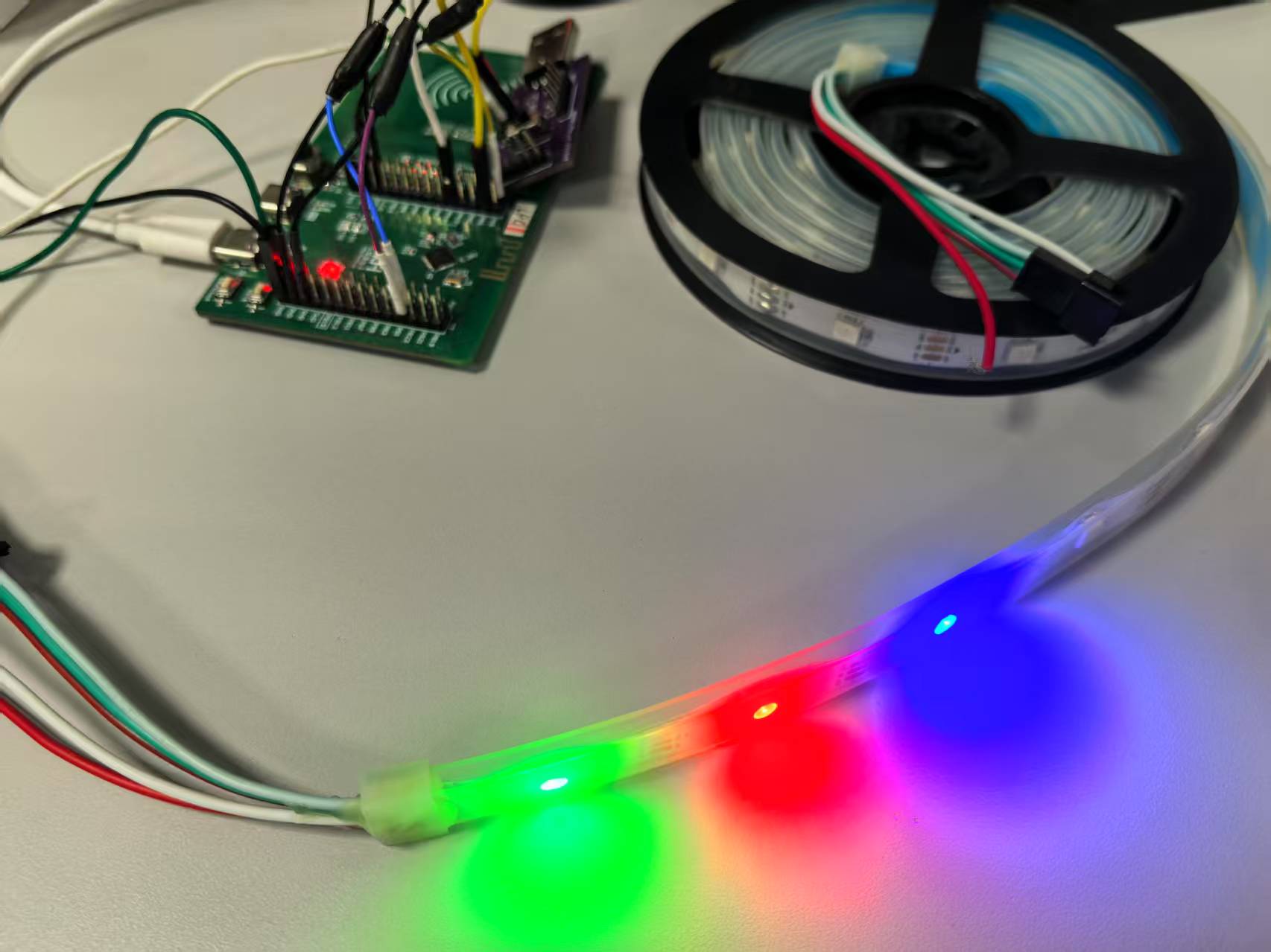
针对CH585的LEDC接口驱动ws2812点灯测试
#include "CH58x_common.h"
#include "ch58x_drv_ledc.h"
#define led_num 3*1
#define breadthe 1
#if !breadthe
__attribute__((__aligned__(4))) uint8_t SPI_Tx_Buffer[] = {
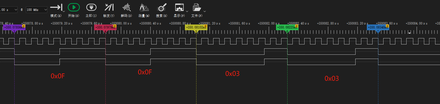
0x0F, 0x0F, 0x0F, 0x0F, 0x0F, 0x0F, 0x0F, 0x0F, // G - 0x01
0x03, 0x03, 0x03, 0x03, 0x03, 0x03, 0x03, 0x03, // R - 0x00
0x03, 0x03, 0x03, 0x03, 0x03, 0x03, 0x03, 0x03, // B - 0x00
0x03, 0x03, 0x03, 0x03, 0x03, 0x03, 0x03, 0x03, // G - 0x00
0x0F, 0x0F, 0x0F, 0x0F, 0x0F, 0x0F, 0x0F, 0x0F, // R - 0x01
0x03, 0x03, 0x03, 0x03, 0x03, 0x03, 0x03, 0x03, // B - 0x00
0x03, 0x03, 0x03, 0x03, 0x03, 0x03, 0x03, 0x03, // G - 0x00
0x03, 0x03, 0x03, 0x03, 0x03, 0x03, 0x03, 0x03, // R - 0x00
0x0F, 0x0F, 0x0F, 0x0F, 0x0F, 0x0F, 0x0F, 0x0F, // B - 0x01
};
#endif
#define LSB_HSB 0 // LED串行数据位序, 1:高位在前; 0:低位在前
#define POLAR 0 // LED数据输出极性, 0:直通,数据0输出0,数据1输出1; 1为反相
#define WS2812_BUFFER_SIZE 24 // R/G/B各8字节
uint8_t ws2812_buffer[WS2812_BUFFER_SIZE]; // 总缓冲区:R[0-7], G[8-15], B[16-23]
void gray_to_red_array(uint8_t gray) {
for (int i = 0; i < 8; i++) {
ws2812_buffer[i] = (gray & (0x80 >> i)) ? 0x0f : 0x03;
}
}
__HIGH_CODE
void ch58x_led_controller_send_TEST(uint32_t *data, uint16_t length)
{
R32_LED_DMA_BEG = ((uint32_t)(data) & RB_LED_DMA_BEG);
R16_LED_DMA_LEN = length;
R8_LED_CTRL_MOD |= RB_LED_DMA_EN;
}
void DebugInit(void)
{
GPIOA_SetBits(GPIO_Pin_14);
GPIOPinRemap(ENABLE, RB_PIN_UART0);
GPIOA_ModeCfg(GPIO_Pin_15, GPIO_ModeIN_PU);
GPIOA_ModeCfg(GPIO_Pin_14, GPIO_ModeOut_PP_5mA);
UART0_DefInit();
}
int main()
{
uint32_t breath_counter = 0;
HSECFG_Capacitance(HSECap_18p);
SetSysClock(CLK_SOURCE_HSE_PLL_78MHz);
/* 配置串口调试 */
DebugInit();
PRINT( "Start @ChipID=%02X\n", R8_CHIP_ID );
{
GPIOB_ResetBits(GPIO_Pin_0|GPIO_Pin_1);
GPIOB_ModeCfg( GPIO_Pin_0|GPIO_Pin_1, GPIO_ModeOut_PP_5mA );
}
//led clk
GPIOA_ResetBits(GPIO_Pin_4);
GPIOA_ModeCfg( GPIO_Pin_4, GPIO_ModeOut_PP_5mA );
//led data //LED 0-7
GPIOA_ResetBits(GPIO_Pin_0);
GPIOA_ModeCfg(GPIO_Pin_0, GPIO_ModeOut_PP_5mA );
// GPIOA_ModeCfg(GPIO_Pin_0|GPIO_Pin_1|GPIO_Pin_2|GPIO_Pin_3|GPIO_Pin_5|GPIO_Pin_6|GPIO_Pin_7|GPIO_Pin_8, GPIO_ModeOut_PP_5mA );
//配置分频和模式选择
ch58x_led_controller_init(CH58X_LED_OUT_MODE_SINGLE, 12);//128);
//开始发送,后面再发送就在中断里面发送了
// R32_LED_DMA_BEG = ((uint32_t)(SPI_Tx_Buffer)& RB_LED_DMA_BEG);
// R16_LED_DMA_LEN = 2*led_num;
// R8_LED_CTRL_MOD |= RB_LED_DMA_EN;
#if LSB_HSB //LSB HSB
R8_LED_CTRL_MOD ^= RB_LED_BIT_ORDER;
#endif
#if POLAR //极性
R8_LED_CTRL_MOD ^= RB_LED_OUT_POLAR;
#endif
LED_ENABLE();
PFIC_EnableIRQ(LED_IRQn);
#if !breadthe
while(1){
ch58x_led_controller_send_TEST((uint32_t*)SPI_Tx_Buffer, 2*9);//定义u8,强转为u32,因此数组从8个元素变成了2个元素,所以长度传入2。
mDelaymS(100);
}
#else
while(1){
uint16_t pos = breath_counter % 512;
if (pos > 255) pos = 511 - pos;
uint8_t gray = (pos * pos) >> 8;
gray_to_red_array(gray);
ch58x_led_controller_send_TEST((uint32_t*)ws2812_buffer, 2*led_num);
breath_counter++;
DelayMs(10); // 调整延时控制呼吸速度
}
#endif
while(1);
}
__INTERRUPT
__HIGH_CODE
void LED_IRQHandler(void){
if((R16_LED_STATUS & RB_LED_LOAD_FAIL)){
LED_ClearITFlag(RB_LED_IF_DMA_END); // 清除中断标志
#if 0
GPIOB_SetBits(GPIO_Pin_1);
uint16_t LED_status;
LED_status = R16_LED_STATUS;
R16_LED_STATUS = LED_status;
R8_LED_CTRL_MOD &= ~RB_LED_DMA_EN;
R8_LED_CTRL_MOD &= ~RB_LED_OUT_EN;
GPIOA_ResetBits(GPIO_Pin_0);//手动拉低数据线,作为reset信号
GPIOB_ResetBits(GPIO_Pin_1);
#endif
}
}

 浙公网安备 33010602011771号