
ABB AC900F学习笔记47:Freelance_Mounting_and_Installation_AC_900F_Controller-7
继续学习AC900安装配置文档,英文版的资料看起来还是不顺畅。
3.1.1 CPU modules PM 904F, PM 902F and PM 901F
CPU模板PM 904F、PM902F、PM901F

上图中
Slots for interface modules 接口模板插槽,这里是放置CI系列模板的
Enthernet interface 以太网接口
Diagnostic interface 诊断接口
Serial interface串口
LEDs LED状态显示灯
SD CARD Slot SD卡插槽
Operating elements 操作元素
Power supply 电源
3.1.2 Features
功能
The essential features of the PM CPU module are listed below
PM CPU系列的基本功能如下:
- Power-PC processor (RISC architecture)
-
电源 PC 处理器(RISC 架构)(RISC架构后面再介绍)
- Main memory for data and application
- 用于数据和应用的主内存
- Slots for Fieldbus communication interfaces
- 用于现场总线通讯接口的插槽
- I/O bus for direct connection of I/O modules
- 用于IO模块直连的IO总线
- On-board communication interfaces
- On-board communication interfaces
- 板载下列通讯接口
–Ethernet 以太网
–RS 232/485
–I/O bus
–Coupler bus
- 24 V DC supply voltage
- 24VDC电源
- SD card reader
- SD读卡器
- Display and control elements
- 显示和控制元素
- Convection cooling without temperature derating
- 对流冷却不减温
- Main memory with error detection/correction
- 带错误检测/纠正的主存储器
- Display (dot matrix LCD display) as an optional accessory
- 显示器(点阵液晶显示器)作为选配配件
3.1.3 Interfaces
接口
The PM CPU module features the following on-board interfaces:
PM CPU模块具有以下板载接口:
Ethernet interfaces 以太网接口
–ETH1, Control Net 网口1 控制网
–ETH2, redundancy link / depending on application 网口2 冗余连接/依据应用
–ETH3, Control Net / depending on application 网口3 控制网/依据应用
–ETH4, (not PM 901F) depending on application 网口4(PM 901F没有此接口) 依据应用
Serial interfaces 串口
–SER1, depending on application 串口1 依据应用
–SER2, depending on application 串口2 依据应用
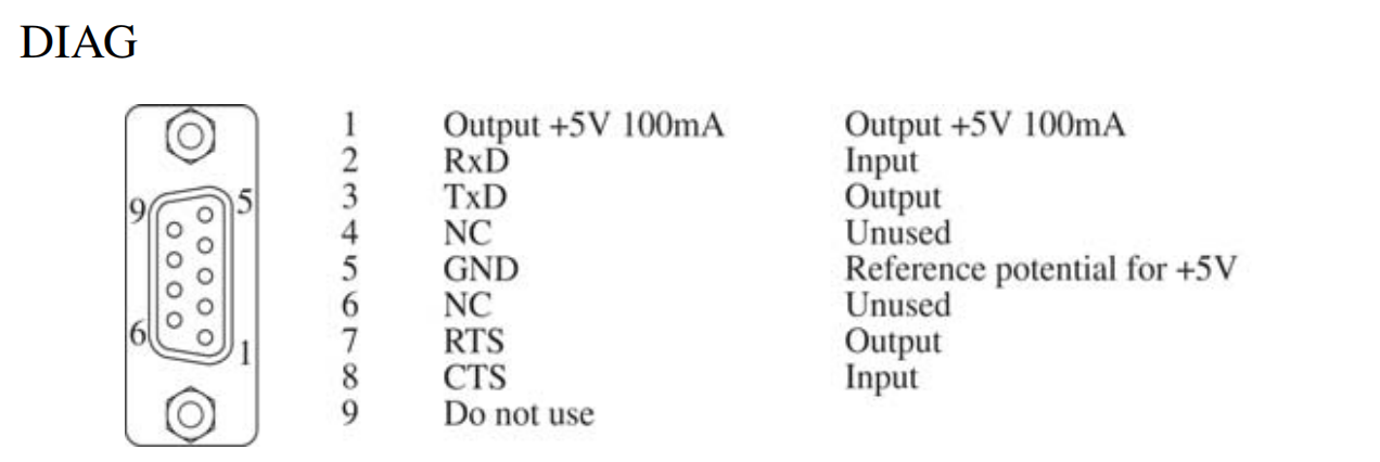
–DIAG, diagnostics, settings and radio clock 诊断端口 设置和广播时钟
Power supply unit 电源单元
–DC-IN +/-24 V DC
Coupler bus 耦合器总线
–C1
–C2
–C3 (PM 904F only) 只有PM904才有
–C4 (PM 904F only) 只有PM 904才有
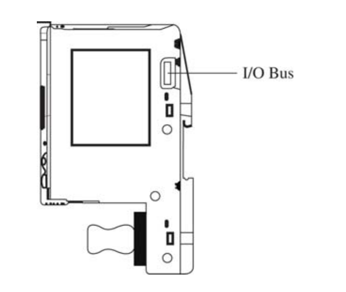
I/O bus
–Connection on the right 在CPU右边连接
For more detailed information refer to the Mounting and Installation Instructions, I/O Modules for AC 700F / AC 900F.
详见《he Mounting and Installation Instructions, I/O Modules for AC 700F / AC 900F》
Power supply
An external 24 V DC voltage supply of sufficient power is required for operating the CPU module, the modules on the C1-C4 slots and for the I/O bus. The DC-IN connection is used for power supply. The corresponding supply lines must be connected to the removable 5-pin terminal block.
保证CPU、C1-C4槽位模块和I/O总线正常运行需要对其外界24VDC电源。直流DC-IN用于电源连接。相应的供电线路必须连接到可移动的5针端子排上.
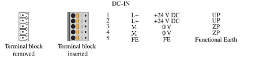
L+ and M are provided twice, which allows also I/O modules or external sensors to be supplied using these terminals.
L+ 和 M 有两个,允许 I/O 模块或外部传感器使用这些终端供电。
The following instructions must be thoroughly read and observed to ensure safe operation
为确保安全,请仔细阅读并遵守以下声明进行操作
- Make sure that the maximum supply voltage (see Section 9, Technical Data) for modules, sensors and other devices is not exceeded. A module supply voltage of more than 32,5 V DC may lead to irreversible damage and destruction of the system.
- 确保给模块、传感器和其它设备的电压不超最大供电电压(参见第九章,技术数据)。模块供电电压超过32.5VDC可能会造成系统不可逆的损坏和破坏。
-
Incorrect wiring (e.g. +/- of the power supply is connected to both L+/L+ or M/M) will cause a short circuit. This may trip the fuse of the power supply unit or damage the switch-mode power supply unit. For general information on safety and precautionary measures, please refer to the Safety Instructions for the AC 700F/AC 900F.
- 不正确的接线(例如电源的+/-连接到L+/L+或M/M)将导致短路。这可能会导致电源单元的保险丝断开或损坏开关电源单元。有关安全及预防措施的一般资料,请参阅AC 700F/AC 900F的安全指引。
Ethernet interfaces
以太网接口
The on-board Ethernet network interfaces of 100 Mbit/s can be used for communication between the controllers, gateways, control station and engineering stations as well as for Ethernet-based field devices to support Modbus TCP or Telecontrol protocol as per IEC-104
板载100Mbits/s以太网接口可用于控制器、网关和工程站之间的通讯,也可用于基于以太网的现场设备,以支持IEC-104的Modbus TCP或Telecontrol协议。
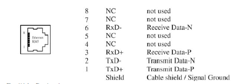
上图绘制了RJ45接口8个针脚的作用
8. 没有使用
7. 没有使用
6. 接收数据-
5. 没有使用
4. 没有使用
3. 接收数据+
2. 发送数据-
1. 发送数据+
For more detailed information on the wiring of the Ethernet interface, please refer to Section 6, Wiring.
有关以太网接口布线的详细信息,请参见第6章布线
Serial interfaces
串口
A removable 9-pin terminal block is used for the connection to both SER1 and SER2 serial interfaces of the CPU module. The SER1 and SER2 interfaces can be configured (and provided with termination resistors) for RS-232 or RS-485 and used for Modbus RTU and Telecontrol protocol as per IEC 60870-5-101 (depending on the terminals used). For more detailed information on the wiring of the series interfaces, please refer to Section 6, Wiring.
CPU模板的串口1和串口2使用可拆除9针端子块。串口1和串口2可以按照IEC 60870-5-101标准(依据段子使用方式)为MODBUS RTU和Telecontrol协议配置为RS-232或者RS-485接线方法(提供终端电阻)。有关系列接口布线的更多详细信息,请参阅第 6 节,接线。
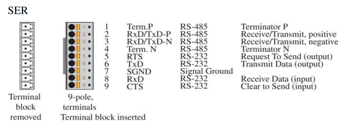
Terminal block removed 可移除式接线端子
9-pole,terminals terminal block inserted 插入9针接线端子块
1. Term.p RS-485 Ternimator.P 1#接线端子 RS-485 端子P
2. RxD/TxD-P RS-485 Receive/Transmit.Positive 2#接线端子 RS-485 收/发端子 阳极(+)
3. RxD/TxD-N RS-485 Receive/Transmit.Positive 3#接线端子 RS-485 收/发端子 阴极(-)
4. Term.p RS-485 Ternimator.N 4#接线端子 RS-485 端子N
5. RTS RS-232 Request to send(Output) 5#接线端子 RS-232 发送请求
6. TxD RS-232 Transmit Data (OUT) 6#接线端子 RS-232 发送数据
7. SGND RS-232 Gignal Grand
8. RxD RS-232 Receive Data(input) 8#接线端子 RS-232 接收数据
9. CTS RS-232 Clear to Send 9#接线端子,RS-232 清除发送
PM CPU 模块具有最多四个耦合总线插槽,用于连接其他通信接口,例如 CI PROFIBUS 模块。
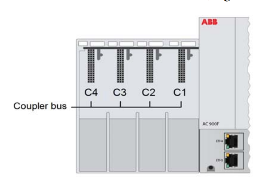
未使用的插槽必须覆盖 TA 虚拟对联器,以符合 ISA 74.01 G3 要求。
I/O bus
IO总线
PM CPU 模块右侧的 I/O 总线提供通信与直接连接到 CPU 模块的 I/O 模块。总线服务在 CPU 模块和 I/O模块 之间交换 I/O 数据和诊断数据。

 浙公网安备 33010602011771号