GPIO openwrt
http://wiki.openwrt.org/doc/devel/add.new.device
http://blog.csdn.net/jiangyuexiang/article/details/7997556
GPIO到文件系统的映射 (2011-06-18 16:19)
标签: 文件系统 寄存器 shell 成功 分类: ARM Linux Fs
控制GPIO的目录位于:
/sys/class/gpio/sys/class/gpio/export
文件用于通知系统需要导出控制的GPIO引脚编号
/sys/class/gpio/unexport
用于通知系统取消导出
/sys/class/gpio/gpiochipX
目录保存系统中GPIO寄存器的信息,
包括每个寄存器控制引脚的起始编号base,寄存器名称,引脚总数
导出一个引脚的操作步骤
1.计算此引脚编号,引脚编号 = 控制引脚的寄存器基数 + 控制引脚寄存器位数
2.向/sys/class/gpio/export写入此编号,比如12号引脚,在shell中可以通过以下命令实现,命令成功后生成/sys/class/gpio/gpio12目录,如果没有出现相应的目录,说明此引脚不可导出:
echo 12 > /sys/class/gpio/export
3.direction文件,定义输入输入方向,可以通过下面命令定义为输出
echo out > direction
注意:direction接受的参数:in, out, high, low。high/low同时设置方向为输出,
并将value设置为相应的1或0。
Playing with GPIO and sensors on OpenWrt
http://hacklabos.org/2014/04/playing-with-gpio-and-sensors-on-openwrt/
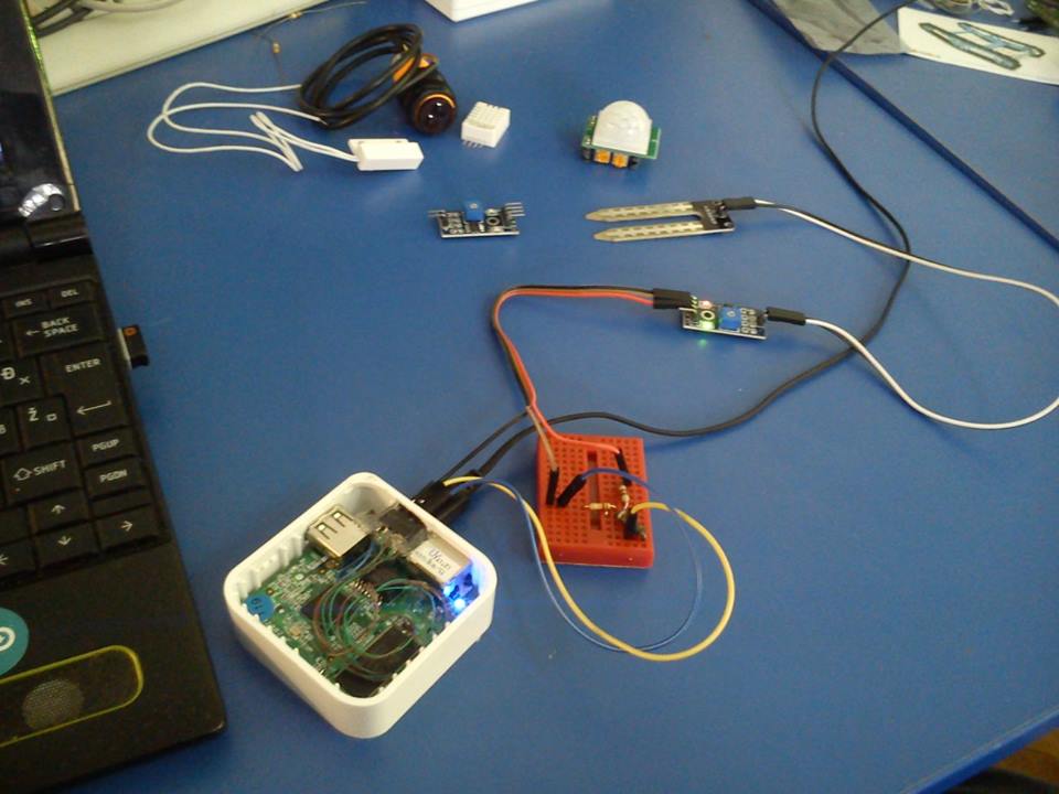
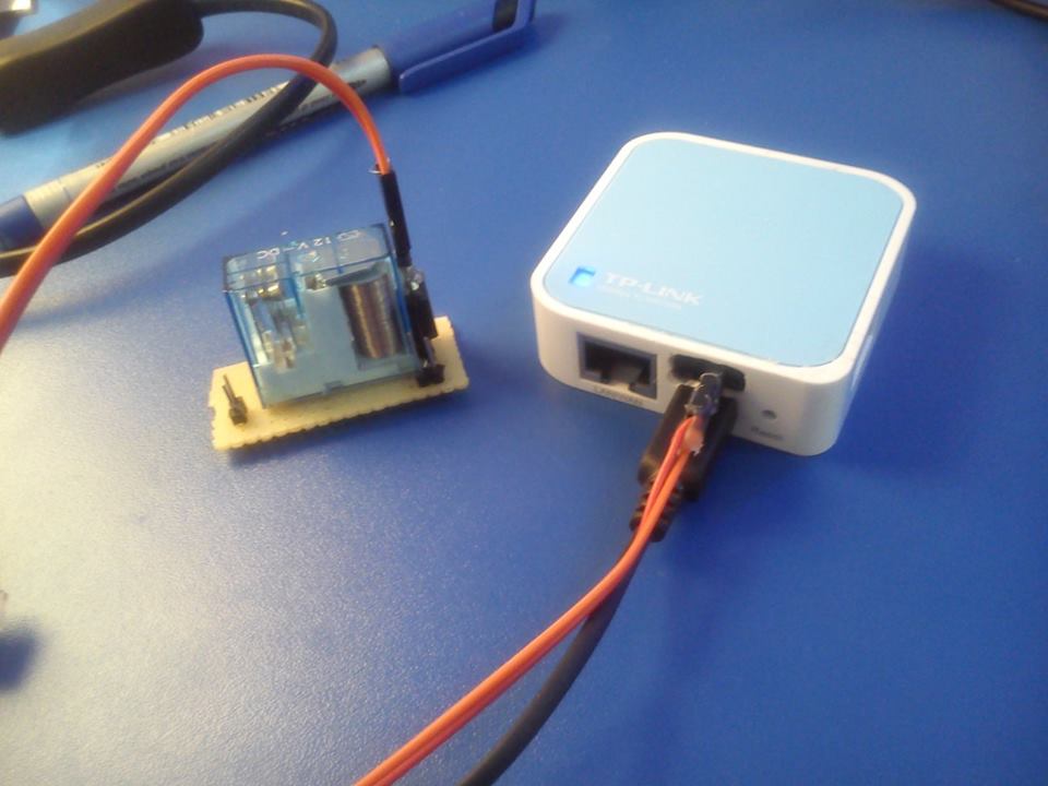
Here are a few examples of using GPIO as input and output on a Tplink TL-WR 703n. This router has three easily accessible GPIO pins you can use.
Most of the time you can find maped GPIO pins on the OpenWrt table of hardware, for 703n look here!
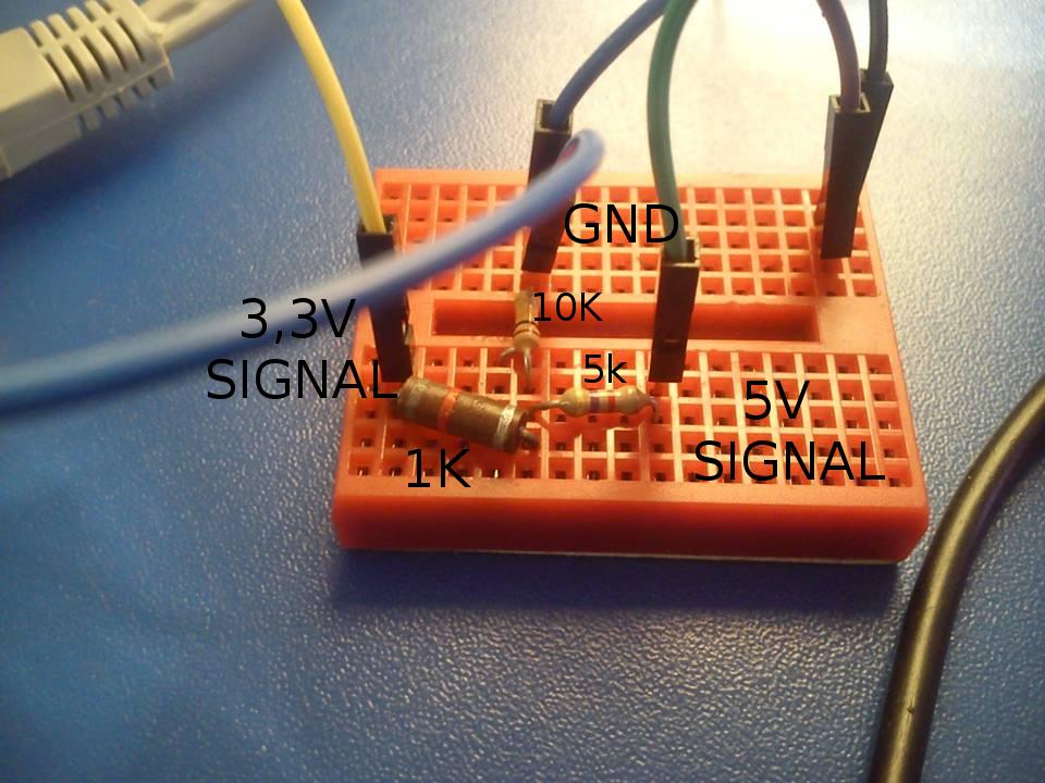
To conect 5V sensors that are intended for use with Arduino you need 5V, GND and a voltage divider to get a signal in 3.3V range instead of 5V, Just to be on the safe side I connected a 1K resistor between the voltage devider and the sensor to limit the current passing trough the GPIO.
Next connect the 5V to the VCC on the sensor, ground to sensor GND and voltage devider GND, Signal output from the sensor to the voltage devider input and the voltage devider output to the current limiting ressistor and then to GPIO.
To be safe you can use a multimeter to mesure voltage before connecting the 3,3V signal to the GPIO pin.
Voltage devider:
OpenWrt setup
I use GPIO 29 so for input the setup looks like this:
/etc/rc.local:
# Put your custom commands here that should be executed once
# the system init finished. By default this file does nothing.
echo “29” > /sys/class/gpio/export;
echo “in” > /sys/class/gpio/gpio29/direction
exit 0
And you can get the state of the pin with:
cat /sys/class/gpio/gpio29/value
And this is what you get:
(some sensors send inverted values, its up to you to use what you need)
root@OpenWrt:~# cat /sys/class/gpio/gpio29/value
1
root@OpenWrt:~# cat /sys/class/gpio/gpio29/value
0
root@OpenWrt:~# cat /sys/class/gpio/gpio29/value
1
Input:
E18-D80NK Optical sensor:

Arduino compatible moisture sensor:
The moisture sensor has a neat analog-digital converter with adjustible treshold that can be used on loads of analog sensors like piezos or microphones: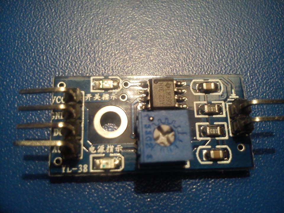
Arduino compatible PIR sensor:

Reed switch:
The reed switch has only two contacts 5V and signal output,so in this case you connect the ground only to the voltage devider.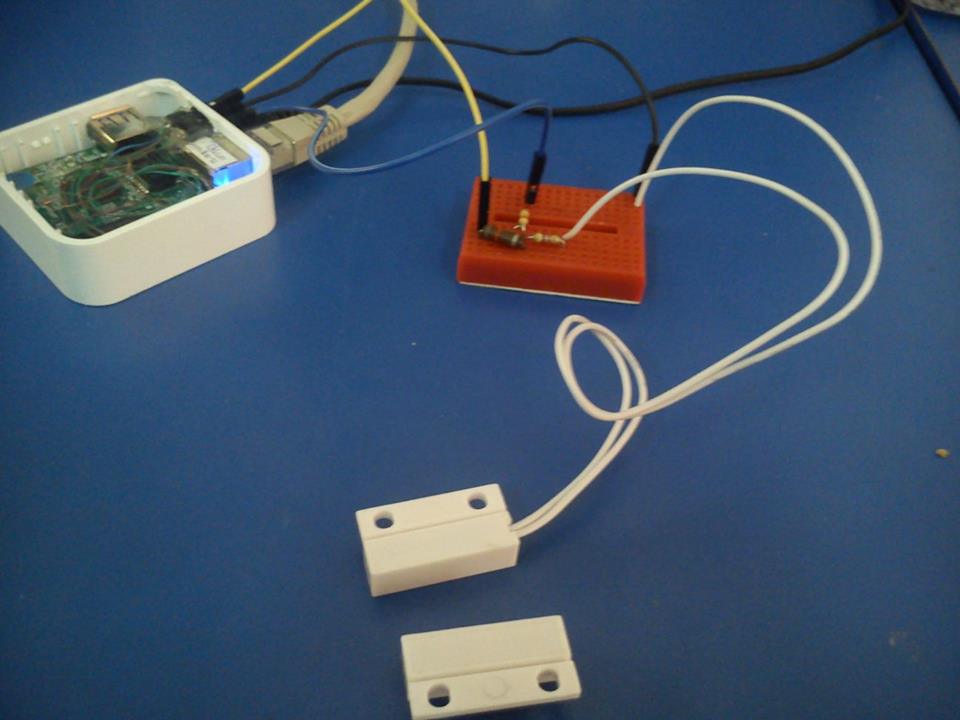
Output:
And /etc/rc.local for output
# Put your custom commands here that should be executed once
# the system init finished. By default this file does nothing.
echo “29” > /sys/class/gpio/export;
echo “out” > /sys/class/gpio/gpio29/direction
exit 0
And than you can control the output with 1 or 0:
echo “1” > /sys/class/gpio/gpio29/value
Control a EM reley:
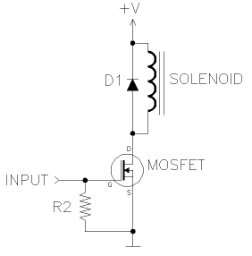
There is a way to get analog reedings on GPIO with a simple RC circuit.
This entry was posted in Projects and tagged #labos, GPIO, openwrt, TP-LINK. Bookmark the permalink.

 浙公网安备 33010602011771号