ros2 control 2
app->controller->HW interface -> HW driver-> hardware
controller
创建一个pkg,在pkg中新建一个controller.yaml。
点击查看代码
controller_manager:
  ros__parameters:
    update_rate: 50

    joint_state_broadcaster:
      type: joint_state_broadcaster/JointStateBroadcaster

    diff_drive_controller:
      type: diff_drive_controller/DiffDriveController

diff_drive_controller:
  ros__parameters:
    left_wheel_names: ["base_left_wheel_joint"]
    right_wheel_names: ["base_right_wheel_joint"]

    wheel_separation: 0.45
    wheel_radius: 0.1

    odom_frame_id: "odom"
    base_frame_id: "base_footprint"

    pose_covariance_diagonal: [0.001, 0.001, 0.001, 0.001, 0.001, 0.01]
    twist_covariance_diagonal: [0.001, 0.001, 0.001, 0.001, 0.001, 0.01]

    enable_odom_tf: true
    publish_rate: 50.0

    linear.x.max_velocity: 1.0
    linear.x.min_velocity: -1.0
    angular.z.max_velocity: 1.0
    angular.z.min_velocity: -1.0
HW driver
写一个节点驱动硬件,colcon build,然后直接ros2 run。
HW interface
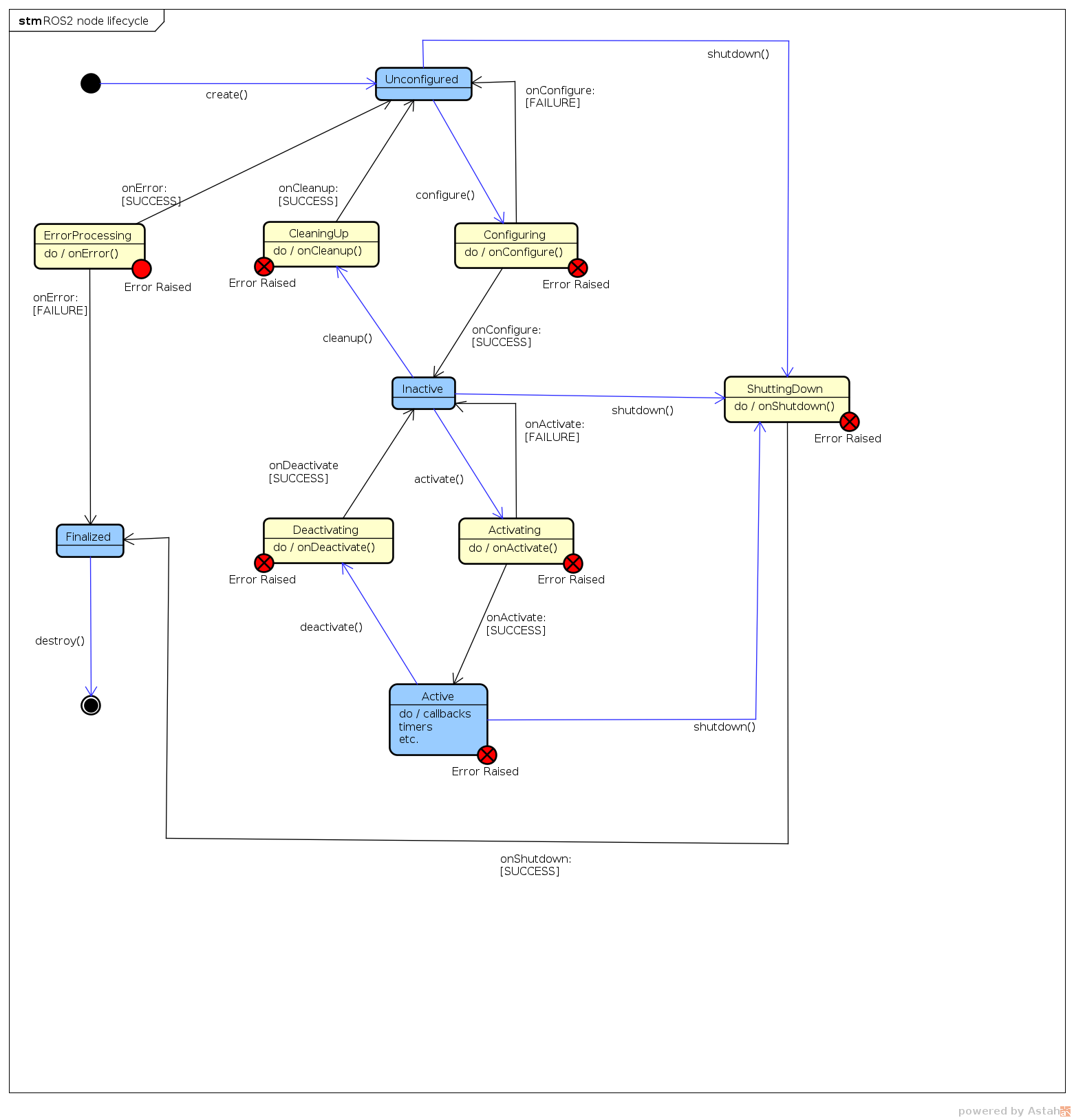
新建hardware interface继承hardware_interface::SystemInterface。在新的类中选择需要覆盖的函数,参照node lifecycle。
点击查看代码
namespace mobile_base_hardware {

class MobileBaseHardwareInterface : public hardware_interface::SystemInterface
{
  // Lifecycle node override
    hardware_interface::CallbackReturn
        on_configure(const rclcpp_lifecycle::State & previous_state) override;
    hardware_interface::CallbackReturn
        on_activate(const rclcpp_lifecycle::State & previous_state) override;
    hardware_interface::CallbackReturn
        on_deactivate(const rclcpp_lifecycle::State & previous_state) override;
    // SystemInterface override
    hardware_interface::CallbackReturn
        on_init(const hardware_interface::HardwareInfo & info) override;
    //从硬件读取数据
    hardware_interface::return_type
        read(const rclcpp::Time & time, const rclcpp::Duration & period) override;
    //向硬件发送数据
    hardware_interface::return_type
        write(const rclcpp::Time & time, const rclcpp::Duration & period) override;
}
}
在实现的cpp后增加宏定义,将hardware interface作为plugin
#include "pluginlib/class_list_macros.hpp"

PLUGINLIB_EXPORT_CLASS(mobile_base_hardware::MobileBaseHardwareInterface, hardware_interface::SystemInterface)
然后创建my_robot_hardware_interface.xml,path中填写pkg的名字。
<library path="my_robot_hardware">
<class name="mobile_base_hardware/MobileBaseHardwareInterface" type="mobile_base_hardware::MobileBaseHardwareInterface" base_class_type="hardware_interface::SystemInterface">
<description> Hardware interface for a mobile base with 2 Dynamixel motors </description>
</class>
</library>
在cmakelist中添加
pluginlib_export_plugin_description_file(hardware_interface my_robot_hardware_interface.xml)
设置好interface后在controller的xacro中的plugin替换为,plugin使用xml中的class name。
<plugin>mobile_base_hardware/MobileBaseHardwareInterface</plugin>
<param name="left_motor_id">10</param>
<param name="right_motor_id">20</param>
<param name="dynamixel_port">/dev/ttyACM0</param>
要点总结:
- Step 0 (watch this first): setup the provided code and visualize the URDF for the
mobile base and robotic arm on top. - Step 1: add a ros2_control tag for the robotic arm
- Step 2: configure a controller
- Step 3: test the controller with a mock component
- Step 4: write a hardware interface (.hpp and .cpp files)
- Step 5: create a plugin out of the hardware interface
- Step 6: test the hardware interface and debug if needed
Some tips to help you get started:
- For each joint we will need one command position and one state position interface.
- You can use the forward_command_controller/ForwardCommandController
controller. Search for it on GitHub to find what parameters you need to provide. - You can add the new controller config in the same file as the one we used before.
- For the hardware interface, create a new interface named ArmHardwareInterface in
the my_robot_hardware package. - To create a plugin for that interface, add a new
tag inside the tag of
the .xml plugin file. - If you’re using the same hardware as me (2 motors), then use a mock component for
the mobile base and the real hardware interface for the arm.

 浙公网安备 33010602011771号