CCIE DC Multicast Part 4.
Hi Guys,
Part 4 of my CCIE DC multicast article is presented below, in this article we are going to look at Rendezvous points discovery mechanisms including Auto-RP and Boot Strap Router (BSR), then Anycast RP. You probably have seen from my blog posts so far the standard method of assigning an RP:
下面是CCIE DC组播文章的第四部分,在这个章节我们将了解RP发现机制,包括自动RP和BSR和Anycast RP,你可能见过我前面博客里用的标准指派RP的方法:
ip pim rp-address
but as your multicast network grows, this could potentially become less scalable than you might like, so let's look at some other options.
但是随着你的组播网络增长,这可能比你想要的扩展程度小,所以我们看看其他选项。
Auto RP
Auto RP is a cisco proprietary method that to be honest is not really used as much anymore now that PIMv2 is available, but for completeness we will go over it.
Auto RP是思科私有的方式,老实说使用的不多,目前PIMv2支持此方式,为了学习完整性,我们也学习它
The way it works is that all PIM enabled routers automatically join the Cisco-RP-Discovery multicast group (which is 224.0.1.40), in order to receive RP mapping information.
它工作的方式是为了接收RP映射信息,所有PIM的路由器自动的加入到Cisco-RP-Discovery multicast group (which is 224.0.1.40)
RP Mapping info is sent (sourced) to this group by a cisco router configured as a mapping agent. Multiple mapping agents can be configured for redundancy purposes.
通过一个路由器被配置为映射代理后,RP映射信息是被发送到的这一个组播组,为了冗余目的多个映射代理是可以被配置的
A mapping agent also joins the group 224.0.1.39 in order to learn which routers in a network are potentially RP's. Candidate RP's source there candidacy as an RP to this multicast group by sending an RP_Announce message to this Cisco-RP-Announce group.
一个映射代理也加入到group 224.1.1.39为了学习网络里哪些路由器是可能的RPs,RP候选源通过使用RP_Announce message 发送他们的RP身份到这个组播组
If multiple RP's announce there candidacy, highest IP address wins
如果有多个RP候选声明,最高ip地址的获胜
The mapping agent then distributes this information to the 224.0.1.40 as an RP_Discovery message.
然后映射代理然后分发RP消息到224.0.1.40组
Without further explanation let's dive right in!
没有更多的解释,让我们直接使用它
For this lab we will go back to our original topology,
为了这个实验,我们回到原始的拓扑:
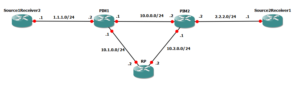
In this we will make our RP the candidate via autoRP and make sure all our other devices discover it.
我们将我们的RP使用autoRP候选出来,并且确保所有的设备都能发现它
PIM2 will act as our mapping agent.
PIM2扮演我们的映射代理
First of all, if we look on PIM1:
首先,我们看下PIM1
PIM1#show ip mroute
IP Multicast Routing Table
Flags: D - Dense, S - Sparse, B - Bidir Group, s - SSM Group, C - Connected,
L - Local, P - Pruned, R - RP-bit set, F - Register flag,
T - SPT-bit set, J - Join SPT, M - MSDP created entry, E - Extranet,
X - Proxy Join Timer Running, A - Candidate for MSDP Advertisement,
U - URD, I - Received Source Specific Host Report,
Z - Multicast Tunnel, z - MDT-data group sender,
Y - Joined MDT-data group, y - Sending to MDT-data group,
V - RD & Vector, v - Vector
Outgoing interface flags: H - Hardware switched, A - Assert winner
Timers: Uptime/Expires
Interface state: Interface, Next-Hop or VCD, State/Mode
(*, 224.0.1.40), 00:26:20/00:02:36, RP 0.0.0.0, flags: DCL
Incoming interface: Null, RPF nbr 0.0.0.0
Outgoing interface list:
GigabitEthernet1/0, Forward/Sparse, 00:22:19/00:02:32
You can see we have as we mentioned, already joined the multicast group 224.0.1.40, but look at those flags, one of them is D for Dense! But we specified sparse mode!
你可以看到我们已经提到过的,已经加入了组播组224.0.1.40,但是看看这些标志位,其中D代表Dense,但是我们指定的是Sparse模式
The problem with the auto-RP mechanism is that the RP info is distributed via multicast.. now if we don't forward multicast, because we don't have an RP and we are in sparse mode.. you can see that this would present a chicken and egg problem, so these groups are automatically put into Dense mode so that the traffic can propogate across the network (potential attack vector? you decide)
对于这个auto-rp机制的问题就是RP信息是通过组播发送的,但是现在如果我们没有转发组播,因为我们还没有RP我们处在sparse-mode模式下,所以你看到这个就成了鸡和蛋的问题了,所以这些组自动的进入了Dense模式,以至于让流量能贯穿网络
So, let's make RP announce itself.
所以,做它自己做一个RP声明
RP(config)#ip pim send-rp-announce lo1 scope 4
The scope command controls the TTL value of the packet, to make sure that we don't announce our RP candidacy too far into the network (incase you had separate RP's for diffirent areas of your network)
这个scope范围控制包的TTL,确保我们的RP在网络里声明的太远(有些情况下你可能在不同的区域有不同的RP)
Let's look at RP's routing table
看一下RP路由表
RP#show ip mro
(*, 224.0.1.39), 00:00:46/stopped, RP 0.0.0.0, flags: DP
Incoming interface: Null, RPF nbr 0.0.0.0
Outgoing interface list: Null
(3.3.3.3, 224.0.1.39), 00:00:46/00:02:13, flags: PT
Incoming interface: Loopback1, RPF nbr 0.0.0.0
Outgoing interface list: Null
You can see from above that the RP has now joined the multicast group 224.0.1.39 and infact is showing the (S,G) 3.3.3.3!
你可以看到上面的RP现在已经加入了组播组24.0.1.39 ,事实上显示的(S,G)这个。
RP#debug ip pim
PIM debugging is on
*Feb 14 12:27:07.627: PIM(0): check pim_rp_announce 1
*Feb 14 12:27:07.627: PIM(0): send rp announce
You can see that the RP has even started announcing, but because there are no outgoing interfaces, the RP is not being seen anywhere else. Let's configure our mapping agent Next (PIM2)
你能看到RP已经声明,但是没有出接口,RP还没有被其他地方所看到,让我们配置PIM2为mapping agent
PIM2(config)#ip pim send-rp-discovery scope 4
This will allow PIM2 to suddenly act as the mapping agent, while we where entering this command the following debug showed up on the RP:
这个就是让PIM2去突然的扮演一个mapping agent,同时我们看到输入这个命令以后RP上的debug输出:
*Feb 14 12:28:07.627: PIM(0): check pim_rp_announce 1
*Feb 14 12:28:07.627: PIM(0): send rp announce
*Feb 14 12:29:07.627: PIM(0): check pim_rp_announce 1
*Feb 14 12:29:07.627: PIM(0): send rp announce
*Feb 14 12:29:07.743: PIM(0): Initiating register encapsulation tunnel creation for RP 3.3.3.3
*Feb 14 12:29:07.751: PIM(0): Initial register tunnel creation succeeded for RP 3.3.3.3
*Feb 14 12:29:07.755: PIM(0): Initiating register decapsulation tunnel creation for RP 3.3.3.3
Feb 14 12:29:07.759: PIM(0): Initial register tunnel creation succeeded for RP 3.3.3.3
Feb 14 12:29:08.059: PIM(0): Received v2 Join/Prune on GigabitEthernet2/0 from 10.2.0.1, to us
Feb 14 12:29:08.067: PIM(0): Join-list: (, 239.1.1.1), RPT-bit set, WC-bit set, S-bit set
Feb 14 12:29:08.075: PIM(0): Check RP 3.3.3.3 into the (, 239.1.1.1) entryFeb 14 12:29:08.083: PIM(0): Adding register decap tunnel (Tunnel1) as accepting interface of (, 239.1.1.1).
Feb 14 12:29:08.091: PIM(0): Add GigabitEthernet2/0/10.2.0.1 to (, 239.1.1.1), Forward state, by PIM G JoinFeb 14 12:29:08.807: %LINEPROTO-5-UPDOWN: Line protocol on Interface Tunnel0, changed state to up
*Feb 14 12:29:08.903: %LINEPROTO-5-UPDOWN: Line protocol on Interface Tunnel1, changed state to up
You can see that the mapping agent has joined the multicast group 224.0.1.39
你可以看到mapping agent已经加入了224.0.1.39组播组。
RP:
(*, 239.1.1.1), 00:01:15/00:03:12, RP 3.3.3.3, flags: S
Incoming interface: Null, RPF nbr 0.0.0.0
Outgoing interface list:
GigabitEthernet2/0, Forward/Sparse, 00:01:15/00:03:12
(*, 224.0.1.39), 00:05:15/stopped, RP 0.0.0.0, flags: DC
Incoming interface: Null, RPF nbr 0.0.0.0
Outgoing interface list:
GigabitEthernet2/0, Forward/Sparse, 00:01:27/00:02:25
The RP forwards traffic out GI2/0 which faces PIM2.
RP转发流量出接口G2/0面向的PIM2
On PIM2:
在pim2上:
(3.3.3.3, 224.0.1.39), 00:01:52/00:02:07, flags: LT
Incoming interface: GigabitEthernet1/0, RPF nbr 10.2.0.2
Outgoing interface list:
GigabitEthernet2/0, Forward/Sparse, 00:01:52/00:02:50
GigabitEthernet3/0, Forward/Sparse, 00:01:52/00:02:25
We can see that the RP Mapping agent is forwarding traffic for 224.0.1.39 from this RP
我们能看到RP mapping agent正在从这个RP为224.0.1.39转发流量
On PIM1 there is now a source for traffic to 224.0.1.40:
在PIM1上也有个源到224.0.1.40的流量:
(10.2.0.1, 224.0.1.40), 00:02:53/00:02:05, flags: LT
Incoming interface: GigabitEthernet2/0, RPF nbr 10.1.0.2
Outgoing interface list:
GigabitEthernet1/0, Forward/Sparse, 00:02:53/00:02:23
It's 10.2.0.1, which is PIM2, so we can see here that PIM1 is learning about the RP over this multicast group.
它就是10.2.0.1,PIM2的地址,所以我们看到这 PIM1已经学习了RP在这个组播组上
The following command verifies these mappings:
下面的命令验证这个映射。
PIM1#show ip pim rp mapping
PIM Group-to-RP Mappings
Group(s) 224.0.0.0/4
RP 3.3.3.3 (?), v2v1
Info source: 10.2.0.1 (?), elected via Auto-RP
Uptime: 00:04:02, expires: 00:02:52
This concludes Auto-RP for our purposes, let's move on to BSR.
这已经结论了Auto-RP,下面在看BSR:
Bootstrap Router Mechanism
自举路由器
BSR is very similiar to auto-rp except it does not use multicast to send RP information, instead it uses a hop by hop flooding mechanism.
自举路由器是一个非常类似auto-rp的除了它不使用组播发送RP信息而是它是通过逐跳的泛洪机制。
The key to the BSR mechanism is the boot strap router itself, one of the routers is elected the BSR.
BSR 的关键是自举路由器自己,其中的一个路由器被选举成BSR
The Candidate RP's then inform the BSR via unicast of there candidacy.
RP候选者然后通过单播通知这个BSR他们的候选身份
The BSR then floods this information out all interfaces every 60 seconds. The BSR floods out ALL candidates that it has possibly received, and the PIM routers all run the same hash algorithim to select the most appropriate RP for each group list. leading to all routers selecting the same RP's The reasoning behind this is that if an RP fails, all the routers in the PIM network have all the info they need straight away to select another RP, reducing failure time.
这个BSR然后每60秒泛洪这些信息到所有接口上,BSR会泛洪出它接收到的所有的候选者身份,PIM路由器运行相同的hash算法去选举在每个组列表上最可能的RP,必须所有的路由器选择了相同的RP,这个背后的一个原因就是如果RP故障,在PIM网络里的所有的路由器有这个信息,他们需要直接选择另一个RP出来,减少故障时间
Multiple BSR's may also be configured, the root BSR is elected in a similiar method to how the root of a spanning-tree is selected. BSR priority can be used to determine a primary BSR.
配置多BSR也是可以的,BSR根是需要选举的类似如何选举生成树根一样。BSR优先级可以用于决定谁是主BSR
If no BSR is available, the routers will switch to the statically configured RP address, if none is configured, all groups will switchover to dense mode. so you can see that a lot of focus on high availability has been placed with BSR.
如果没有BSR可用,路由器们将切换到配置的静态RP地址,如果没有被配置,所有组将会切换到Dense模式,所以你可以看到对于BSR的高可用性已经是有很多关注点的。
Let's check out how this works
检查一下它如何工作
In this Example, RP is going to be our candidate RP, and PIM2 will be our BSR.
在这个例子里,RP正在通告RP身份,PIM2是我们的BSR
RP(config)#ip pim rp-candidate lo1
RP#PIM(0): rp adv timer expired
*Feb 14 14:00:19.627: PIM-BSR(0): Build v2 Candidate-RP advertisement for 3.3.3.3 priority 0, holdtime 150
*Feb 14 14:00:19.627: PIM-BSR(0): Candidate RP's group prefix 224.0.0.0/4
*Feb 14 14:00:19.631: PIM-BSR(0): no bootstrap router address
As you can see from above, there is no BSR candidate, so the RP candidate has no one to advertise to, so we need to fix that.
看上面的内容,由于没有指定BSR角色,所以这个RP没有通告出去,我们需要解决一下
Next, we configure PIM2 as a BSR Candidate:
下面我们配置PIM2是BSR
PIM2(config)#ip pim bsr-candidate gi1/0
Suddenly things go a little crazy:
突然有点乱的事情
PIM2#
*Feb 14 14:01:35.507: PIM-BSR(0): Bootstrap message for 10.2.0.1 originated
*Feb 14 14:01:35.571: PIM(0): Received v2 Bootstrap on GigabitEthernet3/0 from 10.0.0.1
*Feb 14 14:01:35.575: PIM-BSR(0): bootstrap (10.2.0.1) on non-RPF path GigabitEthernet3/0 or from non-RPF neighbor 10.2.0.1 discarded
Here we have the PIM2 sending out it's BSR candidacy, remember that BSR candidacy is flooded out all interfaces, you can see that PIM2 actually receives a BSR candidate message on Gi3/0 for itself from PIM1! But it discards it, but the point is clear: the BSR candidate availability is sent out all interfaces.
这我们让这个PIM2发送它的BSR候选者身份,记住BSR身份是泛洪到所有接口的,你可以看到PIM2从G3/0确实收到一个来自PIM1的它自己的BSR候选者身份消息,但是它忽略了,有一点是明确的,BSR候选身份可用是发送到所有接口的
*Feb 14 14:01:36.071: %SYS-5-CONFIG_I: Configured from console by console
*Feb 14 14:01:38.203: PIM(0): Received v2 Candidate-RP-Advertisement on GigabitEthernet1/0 from 10.2.0.2
Feb 14 14:01:38.207: PIM-BSR(0): RP 3.3.3.3, 1 Group Prefixes, Priority 0, Holdtime 150Feb 14 14:01:38.211: (0): pim_add_prm:: 224.0.0.0/240.0.0.0, rp=3.3.3.3, repl = 0, ver =2, is_neg =0, bidir = 0, crp = 0
*Feb 14 14:01:38.215: PIM(0): Added with
*Feb 14 14:01:38.219: prm_rp->bidir_mode = 0 vs bidir = 0 (224.0.0.0/4, RP:3.3.3.3), PIMv2
Here you can see the BSR (PIM2) received a candidate RP message from the RP, so it addeds it as an RP and starts advertising it out.
这里你可以看到BSR(PIM2)从RP那收到了一个候选RP消息,所以它添加了RP并且开始通告它
*Feb 14 14:01:38.219: PIM(0): Initiating register encapsulation tunnel creation for RP 3.3.3.3
*Feb 14 14:01:38.219: PIM(0): Initial register tunnel creation succeeded for RP 3.3.3.3
Feb 14 14:01:38.219: PIM(0): Check RP 3.3.3.3 into the (, 239.1.1.1) entry
*Feb 14 14:01:38.235: PIM-BSR(0): RP-set for 224.0.0.0/4
*Feb 14 14:01:38.235: PIM-BSR(0): RP(1) 3.3.3.3, holdtime 150 sec priority 0
*Feb 14 14:01:38.239: PIM-BSR(0): Bootstrap message for 10.2.0.1 originated
Now that PIM2 itself has an RP, it creates the RP tunnels for multicast traffic delivery, and originates a BSR message so all the other routers can learn about the RP.
现在PIM2自己有个RP,它为组播流量创建了RP隧道,同时生成了BSR消息到所有的其他路由器让他们知道RP
On PIM1 we can confirm this:
在PIM1上我们能确认这个:
PIM1#show ip pim rp mapping
PIM Group-to-RP Mappings
Group(s) 224.0.0.0/4
RP 3.3.3.3 (?), v2
Info source: 10.2.0.1 (?), via bootstrap, priority 0, holdtime 150
Uptime: 00:04:10, expires: 00:02:16
As you can see the router has learnt about the RP via BSR.
你可以看到,路由器已经通告BSR知道了RP信息
Finally, let's look at anycast RP.
最后,我们再看看anycast RP
Anycast RP
The thing about all the above protocols, is that RP recovery takes quite a while! Should the RP die things take quite a while to switch over, and what's worse is both Auto-RP and BSR produce a lot of control plane load just to provide redundancy. So the ultra smart internet engineers said to themselves "What if we could use the unicast routing tables to provide RP redundancy?"
上面所有的协议问题都是RP恢复是需要一段时间的,要花费一些时间进行RP切换,还有就是Auto-RP和BSR共同的问题就是为了提供冗余都需要产生大量控制平面信息,所以比较激进有想法的工程师会说,如果我们要
使用单播路由表来提供RP冗余会怎么样?
And walla, Anycast RP was born.
所以,anycast RP就产生了。
Anycast RP is not really a protocol (well, it is, but more on that later. bare with me here!), what happens is, we specify an RP address that actually exists on two routers as a loopback!
Anycast RP不是一个真实协议(好吧,它可能后来会更多,但是对我不是)我们指派一个真实存在的RP地址到两个路由器的环回地址上。
What this means is, each of our PIM devices will route multicast to the closest RP to them, and in the event that one of the RP's dies, the unicast routing protocol which we know and love will direct each of the devices to the appropriate location. However things are not quite this simple as this will introduce a little problem, which we will cover soon
什么意思,我们每一个PIM设备将路由组播流量到离他们最近RP上,即使其中的一个RP挂掉,我们喜爱的单播路由协议会导向每个设备到适当为位置,但是事情不是这么的简单,也会有一点小问题,我们一会再介绍
Let's check it out!
检查一下:
For this example, we need to modify our topology slightly
对这个实验,稍微要改一下拓扑:

Now we have two RP's for this concept and a single source connected to both.. this will become important shortly!
现在我们有两个RP,单一的源连接到它俩上,这点在一会很重要:
On RP1 and RP2 define a loopback address:
在RP1 和 RP2定义一个回环地址:
interface Loopback1
ip address 4.4.4.4 255.255.255.255
end
Next, we go to our source and check it's route to 4.4.4.4:
现在我们到源端,检查到达4.4.4.4的路由
source#show ip route 4.4.4.4
Routing entry for 4.4.4.4/32
Known via "ospf 1", distance 110, metric 2, type intra area
Last update from 10.1.0.1 on GigabitEthernet1/0, 00:00:12 ago
Routing Descriptor Blocks:
- 10.2.0.1, from 10.2.0.1, 00:00:59 ago, via GigabitEthernet2/0
Route metric is 2, traffic share count is 1
10.1.0.1, from 10.1.0.1, 00:00:12 ago, via GigabitEthernet1/0
Route metric is 2, traffic share count is 1
As you can see, it's route to 4.4.4.4 lists both routers as equal paths, so let's make Source prefer RP2's link:
你看到,到4.4.4.4列出了两个等价路径,下面我们让源端更倾向RP2链路上
!
interface GigabitEthernet1/0
ip ospf cost 20000
end
source#show ip route 4.4.4.4
Routing entry for 4.4.4.4/32
Known via "ospf 1", distance 110, metric 2, type intra area
Last update from 10.2.0.1 on GigabitEthernet2/0, 00:01:10 ago
Routing Descriptor Blocks:
- 10.2.0.1, from 10.2.0.1, 00:01:57 ago, via GigabitEthernet2/0
Route metric is 2, traffic share count is 1
Now our preferred path to 4.4.4.4 is via Gi2/0, Great!
现在去往4.4.4.4经过的是G2/0了,很好。
(please note that all of this is optional at this point, I am just doing it to show you what Anycast RP "breaks.." you will see in a minute)
提示:这些都是可选项,我这么做只是想展示当anycast rp坏掉的时刻,一会将会看到
so, let's go to each router and add 4.4.4.4 as an RP statically, note that anycast RP can work with auto RP or BSR for advertising itself, the only real trick to anycast RP is that we have the same IP address on multiple RP's.
所以,我们到达每个路由器 添加4.4.4.4作为静态RP,提示。anycast也可以工作在aut-rp和BSR下,其实anycast关键的一点就是在多个RP设备上有相同的RP IP地址
On receiver1 and receiver2 let's join the multicast group 239.1.1.1:
在接收端1和接收端2上加入组播组239.1.1.1
Receiver2(config-if)#ip igmp join-group 239.1.1.1
Done, let's now look at the routing tables of RP1 and RP2:
做完,我们现在观察一下RP1和RP2 的路由表
RP1#show ip mroute
IP Multicast Routing Table
(*, 239.1.1.1), 00:00:44/00:02:15, RP 4.4.4.4, flags: SJC
Incoming interface: Null, RPF nbr 0.0.0.0
Outgoing interface list:
GigabitEthernet1/0, Forward/Sparse, 00:00:44/00:02:15
RP2#show ip mroute
(*, 239.1.1.1), 04:34:41/00:02:11, RP 4.4.4.4, flags: SJC
Incoming interface: Null, RPF nbr 0.0.0.0
Outgoing interface list:
GigabitEthernet2/0, Forward/Sparse, 04:34:41/00:02:11
Both RP1 and RP2 are showing an outgoing interface for the traffic for 239.1.1.1, Great! Let's try a ping from the source now.
RP1和RP2都显示有到239.1.1.1的出接口,下面到源端ping一下。
source#ping 239.1.1.1
Type escape sequence to abort.
Sending 1, 100-byte ICMP Echos to 239.1.1.1, timeout is 2 seconds:
Reply to request 0 from 2.2.2.1, 52 ms
Hmmm.. that's weird, i only got a response from one receiver?
呃,有点奇怪,我只得到了一个接收端的响应
The reason is because the RP's are not aware of each others sources for traffic, so when traffic is delivered from the source up to the RP, only one RP gets a copy of it, and only one RP can then deliver that traffic to it's receivers, since they are both not aware of each others receivers and sources, problems will occur like above!
原因是因为RP们不知道互相的流量源端,所以当流量从源端到一个RP的时候,只能这个RP可以复制流量然后到它的接收端上,因为他们彼此没有意识对端收到了组播流,所以发生了上面的问题
If we make source prefer the route via Gi1/0...
如果我们让源端选择G1/0链路...
source(config-if)#int gi2/0
source(config-if)#ip ospf cost 30000
source#show ip route 4.4.4.4
Routing entry for 4.4.4.4/32
Known via "ospf 1", distance 110, metric 20001, type intra area
Last update from 10.1.0.1 on GigabitEthernet1/0, 00:00:28 ago
Routing Descriptor Blocks:
- 10.1.0.1, from 10.1.0.1, 00:00:28 ago, via GigabitEthernet1/0 Route metric is 20001, traffic share count is 1
When we ping the multicast 239.1.1.1 it only responds for our Reciever1 receiver, even though both have joined the group:
当再ping239.1.1.1时,他还是只得到了接收端1的回应,即便两边都加入了这个组播组
source#ping 239.1.1.1 source gi1/0
Type escape sequence to abort.
Sending 1, 100-byte ICMP Echos to 239.1.1.1, timeout is 2 seconds:
Packet sent with a source address of 10.1.0.2
Reply to request 0 from 1.1.1.1, 36 ms
To resolve this problem on IOS we use Multicast Source Discovery Protocol, which as the name probably implies, helps discover sources, originally used for inter-isp multicast routing we use it here to help us with our multiple AP setup.
为了解决这个问题,在IOS平台上我们要使用MSDP组播源发现协议,帮助发现组播源,这个协议最原始的用于多个isp组播路由域之间RP对等体的建立。
RP2(config)#ip msdp peer 1.1.1.2 connect-source gi2/0
RP2(config)#ip msdp originator-id gi2/0
And on RP1 we do the opposite:
RP1(config)#ip msdp peer 2.2.2.2 connect-source gi1/0
*Feb 14 16:57:10.258: %MSDP-5-PEER_UPDOWN: Session to peer 2.2.2.2 going uor
RP1(config)#ip msdp originator-id gi1/0
We can now see a peer relationship between the two over MSDP:
我们能看到在两个RP之间一个MSDP对等体关系
RP1#show ip msdp sum
MSDP Peer Status Summary
Peer Address AS State Uptime/ Reset SA Peer Name
Downtime Count Count
2.2.2.2 ? Up 00:00:25 0 0 ?
Let's see what happens when we ping now...
下面看看再ping会怎么样
source#ping 239.1.1.1 source gi1/0
Type escape sequence to abort.
Sending 1, 100-byte ICMP Echos to 239.1.1.1, timeout is 2 seconds:
Packet sent with a source address of 10.1.0.2
Reply to request 0 from 1.1.1.1, 52 ms
Reply to request 0 from 2.2.2.1, 92 ms
Success!
成功!
Let's check out the Peering command:
再检查一下peer的命令
RP2#show ip msdp peer
MSDP Peer 1.1.1.2 (?), AS ? Connection status:
State: Up, Resets: 0, Connection source: GigabitEthernet2/0 (2.2.2.2)
Uptime(Downtime): 00:00:17, Messages sent/received: 1/2
Output messages discarded: 0
Connection and counters cleared 00:01:17 ago
SA Filtering:
Input (S,G) filter: none, route-map: none
Input RP filter: none, route-map: none
Output (S,G) filter: none, route-map: none
Output RP filter: none, route-map: none
SA-Requests:
Input filter: none
Peer ttl threshold: 0
SAs learned from this peer: 1 Number of connection transitions to Established state: 1
Input queue size: 0, Output queue size: 0
MD5 signature protection on MSDP TCP connection: not enabled
Message counters:
RPF Failure count: 0
SA Messages in/out: 1/0
SA Requests in: 0
SA Responses out: 0
Data Packets in/out: 0/0
We can see from the above that we have peer'd with the other RP and that there is an active source address that we are caching
我们能看到来自于上面的我们对等体和缓存活动的源地址信息
RP2#show ip msdp sa-cache
MSDP Source-Active Cache - 1 entries
(10.1.0.2, 239.1.1.1), RP 1.1.1.2, AS ?,00:01:18/00:05:40, Peer 1.1.1.2
Now if we check the show ip mroute for that entry
(10.1.0.2, 239.1.1.1), 00:01:34/00:01:25, flags: M
Incoming interface: GigabitEthernet3/0, RPF nbr 10.0.0.1
Outgoing interface list:
GigabitEthernet2/0, Forward/Sparse, 00:01:34/00:02:36
We can see that there is an entry for this source with an interesting new flag we have not seen before "M", which means "M - MSDP created entry"
我们可以看到有个这个源端的条目和一个有趣的位,之前没有看到过,M意思就是由MSDP创建的条目
Couldn't have said it easier myself
我之前还没有提过它
Now! This is one way to do it with MSDP, however on Nexus operating system (what we will be using in the CCIE DC when we all pass 😉) we actually DO have a protocol called Anycast RP, and the protocol is used to allow two anycast RP's to share information about active sources and is NOT part of MSDP.
现在,这是一种MSDP方式,但是在Nexus交换机上,我们也可以做一个叫Anycast RP,这个协议是允许Anycast RP共享活动的源信息,但它不是MSDP!
To configure on nexus, issue the following commands:
在Nexus上配置,使用下面的命令:
Nexus:
ip pim anycast-rp 172.16.1.1 192.168.10.1
ip pim anycast-rp 172.16.1.1 192.168.10.2
172.16.1.1 is your actual RP address, and 192.168.10.1 is an IP address of the nexus itself (you must specify yourself as being an RP Candidate) and 192.168.10.2 is the other RP Candidate.
172.16.11 是确切的RP地址,192.168.10.1是一个RP候选者的上IP地址,192.168.10.2是另一个RP候选者的上IP地址.
I hope you enjoyed this blog entry, Now that we have covered pretty much the whole nine yards of Multicast I promise the next one will cover how all of this ties into Nexus, the CCIE DC exam and OTV 😃
我希望你们能喜欢这篇文章,现在我们覆盖了相当于9成的组播范围,我答应下一个将涉及的就是如何把这些牵入到Nexus,CCIE DC考试OTV里。
下面是关于OTV 组播的anycast RP配置
Sample OTV configuration as it pertains to multicast:
OTV-1
interface overlay1
otv control-group 239.1.1.1
otv data-group 232.1.1.0/24
interface eth3/1
description OTV Join Interface
ip igmp version 3
OTV-2
interface overlay1
otv control-group 239.1.1.1
otv data-group 232.1.1.0/24
interface eth3/1
description OTV Join Interface
ip igmp version 3
Upstream-Router_OTV-1
feature pim
interface eth3/10
description To OTV Join Interface
ip pim sparse-mode
ip igmp version 3
ip pim rp-address 4.4.4.4 group-list 224.0.0.0/4
ip pim ssm range 232.0.0.0/8
Upstream-Router_OTV-2
feature pim
interface eth3/10
description To OTV Join Interface
ip pim sparse-mode
ip igmp version 3
ip pim rp-address 4.4.4.4 group-list 224.0.0.0/4
ip pim ssm range 232.0.0.0/8
NXOS-RP1:
feature pim
interface loop0
ip address 1.1.1.1 255.255.255.255
ip pim sparse-mode
interface loop1
ip address 4.4.4.4 255.255.255.255
ip pim sparse-mode
ip pim rp-address 4.4.4.4 group-list 224.0.0.0/4
ip pim ssm range 232.0.0.0/8
ip pim anycast-rp 4.4.4.4 1.1.1.1
ip pim anycast-rp 4.4.4.4 2.2.2.2
NXOS-RP2:
feature pim
interface loop0
ip address 2.2.2.2 255.255.255.255
ip pim sparse-mode
interface loop1
ip address 4.4.4.4 255.255.255.255
ip pim sparse-mode
ip pim rp-address 4.4.4.4 group-list 224.0.0.0/4
ip pim ssm range 232.0.0.0/8
ip pim anycast-rp 4.4.4.4 1.1.1.1
ip pim anycast-rp 4.4.4.4 2.2.2.2

 浙公网安备 33010602011771号