CCIE DC Multicast Part 1.
Hi Guys!
As we all wait anxiously for the training vendors to release Rack Rentals (Come on guys! At least give us a FIRM date so we can plan appropriately!) I think it's a good idea to look at things you can study on the cheap that are going to end up in the exam.
One of those things is Multicast, the blueprint specifically mentions there will be multicast troubleshooting and I would bet bottom dollar it's to do with the OTV use of multicast, which means Nexus 7000, which Means PIM. We can test PIM in GNS, we can test PIM on our own home gear, OK the Syntax is not going to match between the platforms all the time, but the CONCEPTS will and CONCEPTS are what pass exams and lead to you being an expert!
The very best multicast book i have read thus far, and where i got most of the information for this blog post can be found at the end of the blog post 😃.
In a first for this blog post, I am going to provide the GNS3 .net file I used to write these tutorials so you can follow along at home or try your own experiments 😃. The GNS files can be found Here. Gns3 itself can be found at www.gns3.net.
Note that I emulated 7200 routers when I did this because the thing about 7200 routers is that in GNS you can run quite recent IOS Images on it, no I will not provide any IOS Images that you need to run it so please don't ask, get yourself a 7200 IOS image OR modify the template to use diffirent routers 😃.
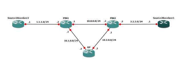
The topology is shown below
Before we go any further, let's take a super quick look at multicast and the different options we are talking about.
在进展之前,我们先简单快速的了解组播和不同的选项
A quick multicast review is in order:
Multicast Basics:
One packet, copied to multiple receivers from a single source (one to many), and always UDP because acknowledgements can't be sent (responses are never sent to multicast traffic)
包,从一个单发送源复制到多个接受者,总使用UDP协议,以为确认消息不能被返回
224.0.0.0 to 239.255.255.255 is set aside for multicast.
224.0.0.0 to 239.255.255.255地址范围用于组播
anything in the 224.0.0.X range is reserved and no matter what these packets are NEVER FORWARDED outside the local subnet, they are strictly internal.
224.0.0.x是预留的,无论何时都不要转发这些包到本地子网之外,它们是严格内部的
224.0.1.X is also a reserved range but does get forwarded.
224.0.1.X也是保留范围不要用于转发
Two very good examples for this range (224.0.1.X) that we will talk about later are 224.0.1.39 and 224.0.1.40 which are used for Cisco AUTO RP Discovery.
在224.0.1.x范围内的两个例子,后面我们也会讨论到它们是224.0.1.39和224.0.1.40,用于Cisco AUTO RP Discovery
The 239.0.0.0/8 range has been set aside for us engineers to use for our own multicast applications.
239.0.0.0/8 范围是用于我们工程师使用配置组播应用
Multicast Routing:
Multicast routing works almost in reverse to traditional routing where by the SOURCE of the traffic is most important. There are a few multicast routing protocols around but for our CCIE DC, We use PIM (Protocol Independent Multicast),
组播路由的工作几乎和传统路由相反,传统路由里流量的始发源很重要。有几个组播路由协议,但对于我们CCIE DC来说,我们只使用PIM
PIM Relies on the unicast routing table already on the router to evaluate it's Reverse Path Forward (RPF) Checks. Hence the term Protocol-independent: Your unicast routing protocol does not matter, PIM just uses the information in the unicast routing table to determine RPF.
PIM依赖存在与路由器上的单播路由表去计算它的反向路径检查。因此属于协议-独立:就是你的单播路由协议无所谓,PIM只是用于单播路由表的信息来决定RPF(反向路径检查)
As traffic travels from a source of multicast traffic (like a video application or music on hold service), the stream travels down the PIM domain from the very top (Source) to all the receivers, due to the fac that loops are avoided, the resultant path the multicast traffic takes from source to receivers resembles a tree, with the root being the source of the traffic.
随着流量从组播源始发(像视频应用或音乐服务),流从顶端(源)穿过PIM域到所有接收端,为了避免环路,组播流量从源到接收端的路径会形似一个树,流量的源就是根
PIM:
There are two versions of PIM, PIM Sparse Mode and Dense Mode, the major difference is in the behavior when forwarding multicast traffic, PIM Dense mode assumes that EVERYONE in the network (or rather, the PIM Domain) wants to hear from a multicast source unless specifically told otherwise, PIM Sparse mode assumes you DON'T want to forward multicast unless you specifically know that you have receivers listening for it.
PIM有两个版本,一个spase mode 一个dense mode,主要的区别是在转发组播流量行为上,dense mode前提假设网络上(pim 区域)所有设备都是组播源的接收者,除非特别指明不接收。spase mode 前提假设你不想接收转发组播除非你特别告诉想接收组播流
PIM Dense mode is quite a simple and straight forward protocol, but leads to quite a bit of waste, and unfortunately from an exam taking point of view, The Nexus platform only supports PIM Sparse Mode. So that's what we will brush up on.
PIM dense mode是相当简单直接的转发方式,但是也相当浪费网络资源,而且从考试要求看,Nexus 平台只支持PIM spase mode,所以我们把它略过了
PIM Sparse Mode
PIM Sparse mode is rooted in the concept of a Rendezvous point. (RP). Earlier in the multicast routing section we talked about the concept of a "tree", with it's root at the "source" of the multicast traffic. But how do you get the routers in a PIM domain to forward the multicast traffic IF by default they are configured not to forward it? A receiver might say "I want to join the multicast group 239.1.1.1", but then how does the router closest to him (which we will call the "last hop router" as it's the closest router to the receiver) know where to send his PIM JOIN msgs (which tell his upstream routers he wants to start receiving multicast for this group), Where do the next hop routers send the PIM Join msg? The Rendezvous point solves this problem. All routers indicate there desire to join a particular multicast stream to the rendezvous Point, and all sources of traffic first somehow deliver traffic to the RP To have the RP Forward the traffic for them. This is known as a SHARED Tree
PIM spase mode 主要核心概念是RP汇聚点,在前面的组播路由章节我们提过树的概念,组播源就是树的根。但是如何让PIM区域里的路由器转发默认没有配置转发的组播流量,一个接收者可能说我想加入组播组239.1.1.1,但是如何让离接收者最近的路由器(也就是最后一跳路由器)知道往哪里发送 PIM JOIN msgs(就是告诉上游路由器它想开始接收这个组的组播流),再上一跳的路由器在把PIM Join msg发到哪。RP就是解决这个问题。所有的路由器表明它们想加入的特定组播组到RP,以及所有的流量源首先转发流量到RP,以至于让RP来转发后续的流量,这就是一个共享树
Key Concept: Shared Tree Vs Shortest Path Tree
关键概念:共享树 vs 最短路径树
However things get a little bit more complicated...
但是事情可能有点复杂...
(Refer to diagram)
In our example, let's say that Source1 is sending multicast that Receiver1 wants to listen to, in our above example, Receiver1 would send a msg to the RP saying "I want to listen to traffic to 239.1.1.1", Source1 would have it's mcast packet delivered to the RP via some method (more on this later), but if you look at the diagram, you can see that this means the traffic must flow like this:
在我们的例子种,我们说Source1 发送Receiver1 想接受的组播流,在前面的例子中,Receiver1想发送一个msg到RP说我想加入239.1.1.1,Source1 通过一些方法已将它的组播包发送到RP(后面会讲),但是你看图,流量必须是黄色线的走向

As you can see this follows a very inefficient path, why can't our multicast stream just travel straight from Source1Receiver2, through PIM1, To PIM2 then to our receiver.
你看到这种流向不是一个有效率的路径,为什么我们不能让组播流转发的更直接从Source1到PIM1到PIM2然后到接收端.
The Answer is: It can, once all the devices in the path know that there is a Source and Receiver, they will switch to a shortest path tree (SPT)
答案是,它可以的,一旦路径上的所有的设备知道了源和接收端。它们将转发到一个最短路径SPT
Now that PIM2 knows there is a multicast source out there, he can send a JOIN msg up the PIM domain towards the source, with routers along the way letting him join.
现在PIM2知道有一个组播源在那,它能基于pim域发送一个join msg到源端,以及沿途的路由器让它加入
Let's watch this in action.
让我们现在这个过程
The default configuration on our router is that we don't have ANY RP's specified on any of the routers, all routers have full reachability via OSPF and are neighbors via PIM (Except for the Two Edge Routers Source1Receiver2 and SOurce2Receiver1 because they are just our multicast source/destinations 😃)
默认配置在我们的路由器上的是没有任何特定any rp的,所有的路由有全可达能力由ospf提供和PIM邻居(除了两个边界路由器Source1Receiver2 and SOurce2Receiver1,因为他们只是组播的源和接收端)
Let's see what happens when we join a group
让我们看发生了什么当我们加到一个组播组后
Source2Receiver1(config)#int gi1/0
Source2Receiver1(config-if)#ip igmp join-group 239.1.1.1
We then run a debug ip pim on PIM2:
*Feb 2 18:29:28.539: IGMP(0): Received v2 Report on GigabitEthernet2/0 from 2.2.2.1 for 239.1.1.1
*Feb 2 18:29:28.543: IGMP(0): Received Group record for group 239.1.1.1, mode 2 from 2.2.2.1 for 0 sources
*Feb 2 18:29:28.543: IGMP(0): WAVL Insert group: 239.1.1.1 interface: GigabitEthernet2/0Successful
*Feb 2 18:29:28.547: IGMP(0): Switching to EXCLUDE mode for 239.1.1.1 on GigabitEthernet2/0
*Feb 2 18:29:28.547: IGMP(0): Updating EXCLUDE group timer for 239.1.1.1
Feb 2 18:29:28.547: IGMP(0): MRT Add/Update GigabitEthernet2/0 for (,239.1.1.1) by 0
Feb 2 18:29:28.555: PIM(0): Building Triggered (,G) Join / (S,G,RP-bit) Prune message for 239.1.1.1
What we can tell from the above is that PIM2 has received the IGMP join for the particular group, but this hasn't generated a message to the RP because there is no RP
我们看到PIM2已经收到了IGMP的join消息,但是没有产生一个消息到RP是因为就没有指定RP
Let's check out the ip mroute table from PIM2:
再来检查一下ip mroute 表
PIM2#show ip mroute
IP Multicast Routing Table
Flags: D - Dense, S - Sparse, B - Bidir Group, s - SSM Group, C - Connected,
L - Local, P - Pruned, R - RP-bit set, F - Register flag,
T - SPT-bit set, J - Join SPT, M - MSDP created entry, E - Extranet,
X - Proxy Join Timer Running, A - Candidate for MSDP Advertisement,
U - URD, I - Received Source Specific Host Report,
Z - Multicast Tunnel, z - MDT-data group sender,
Y - Joined MDT-data group, y - Sending to MDT-data group,
V - RD & Vector, v - Vector
Outgoing interface flags: H - Hardware switched, A - Assert winner
Timers: Uptime/Expires
Interface state: Interface, Next-Hop or VCD, State/Mode
(*, 239.1.1.1), 00:02:14/00:02:47, RP 0.0.0.0, flags: SJC
Incoming interface: Null, RPF nbr 0.0.0.0 Outgoing interface list:
GigabitEthernet2/0, Forward/Sparse, 00:02:14/00:02:47
From the above you can see that PIM2 will forward all traffic for the group 239.1.1.1 to the outgoing interface Gi2/0, but there is no incoming traffic it has seen for this so far so the incoming interface is NULL. The Flags: SJC are also worth understanding, the S simply stands for Sparse and indicates that the group is a sparse mode group, (we kinda already knew that 😉, the C means that there is actually a receiver connected to one of our interfaces, so we know when looking at this that there is a receiver attached directly to us. The J Flag I left until last because it's the most interesting bit:
从上面看PIM2将可以转发所有239.1.1.1到outgoing接口G2/0,但是没有incoming入流量以至于入接口是NULL,这个flag:SJC一样值得理解,S 代表spase mode ,C 代表有一个确切的接收端已经连接到一个接口,以至于我们能知道有一个接收端直接连接到我们,J 是最有趣的一个位
The J Flag says that, as soon as this router see's traffic come in from a source for this particular group, it will straight away after just one packet, switch to a SPT Tree by sending a join message up the PIM domain to that particular source. This is all based off a threshold called the SPT-Threshold, and dictates how many packets must be received before the Shared Tree switches to a source-based tree, the default is 0, which means that as soon as a single packet is received for that mcast group the tree is changed to a source-based tree straight away.
这个J位说,只要这个路由器看到了对于这个特定组的组播流的源,它将在第一个包之后切换成SPT树,通过发送join message到这个特定源。这就是基于一个阈值叫SPT阈值,标示收到多少个包之后从共享树切换成最短路径树,默认是0,意味着只要有一个包收到,就切换成最短路径树。
Let's see what happens if we where to try and generate Traffic to 239.1.1.1:
我们看下如果我们产生一个流量到239.1.1.1会发送什么:
Source1Receiver2#ping 239.1.1.1
Type escape sequence to abort.
Sending 1, 100-byte ICMP Echos to 239.1.1.1, timeout is 2 seconds:
.
No Dice: the traffic won't reach our receivers, let's go to PIM1 and have a look at what he thinks of all this:
PIM1#show ip mroute
IP Multicast Routing Table
Flags: D - Dense, S - Sparse, B - Bidir Group, s - SSM Group, C - Connected,
L - Local, P - Pruned, R - RP-bit set, F - Register flag,
T - SPT-bit set, J - Join SPT, M - MSDP created entry, E - Extranet,
X - Proxy Join Timer Running, A - Candidate for MSDP Advertisement,
U - URD, I - Received Source Specific Host Report,
Z - Multicast Tunnel, z - MDT-data group sender,
Y - Joined MDT-data group, y - Sending to MDT-data group,
V - RD & Vector, v - Vector
Outgoing interface flags: H - Hardware switched, A - Assert winner
Timers: Uptime/Expires
Interface state: Interface, Next-Hop or VCD, State/Mode
(*, 224.0.1.40), 00:01:46/00:02:39, RP 0.0.0.0, flags: DCL
Incoming interface: Null, RPF nbr 0.0.0.0
Outgoing interface list:
GigabitEthernet1/0, Forward/Sparse, 00:01:46/00:02:39
The only entry our friend PIM1 Has is for the 224.0.1.40 (Auto-RP Discovery listening) group, he doesn't even see the traffic source for 239.1.1.1, this is because he has no RP to send the traffic to, so refuses to pass it on.
我们的PIM1只有一个条目是224.0.1.40(Auto-RP Discovery listening)组,它没有看到239.1.1.1条目,这是因为没有配置发送流量到RP的RP,所以它拒绝传送。
Let's delve further, first, On PIM2 (Closest to the receiver) let's assign an RP after stopping listening to the multicast on the receiver1:
让我们在进一步,先关闭监听组播之后 ,在PIM2上指定一个RP
Source2Receiver1(config)#int gi1/0
Source2Receiver1(config-if)#no ip igmp join-group 239.1.1.1
Clear the mroute on PIM2:
PIM2#clear ip mroute *
PIM2#show ip mroute
IP Multicast Routing Table
Flags: D - Dense, S - Sparse, B - Bidir Group, s - SSM Group, C - Connected,
L - Local, P - Pruned, R - RP-bit set, F - Register flag,
T - SPT-bit set, J - Join SPT, M - MSDP created entry, E - Extranet,
X - Proxy Join Timer Running, A - Candidate for MSDP Advertisement,
U - URD, I - Received Source Specific Host Report,
Z - Multicast Tunnel, z - MDT-data group sender,
Y - Joined MDT-data group, y - Sending to MDT-data group,
V - RD & Vector, v - Vector
Outgoing interface flags: H - Hardware switched, A - Assert winner
Timers: Uptime/Expires
Interface state: Interface, Next-Hop or VCD, State/Mode
(*, 224.0.1.40), 00:00:01/00:02:58, RP 0.0.0.0, flags: DPL
Incoming interface: Null, RPF nbr 0.0.0.0
Outgoing interface list: Null
Specify a loopback on the RP Router to act as our RP:
在RP路由器上指定一个回环口作为RP
RP(config-if)#int lo1
RP(config-if)#ip add 3.3.3.3
Specify this as our RP on our PIM2 Router:
在PIM2指定RP地址
PIM2(config)#ip pim rp-address 3.3.3.3
PIM2(config)#
*Feb 2 18:58:56.447: PIM(0): Initiating register encapsulation tunnel creation for RP 3.3.3.3
*Feb 2 18:58:56.455: PIM(0): Initial register tunnel creation succeeded for RP 3.3.3.3
Feb 2 18:58:56.459: PIM(0): Check RP 3.3.3.3 into the (, 224.0.1.40) entry
Feb 2 18:58:56.583: PIM(0): Building Triggered (,G) Join / (S,G,RP-bit) Prune message for 224.0.1.40
*Feb 2 18:58:57.487: %LINEPROTO-5-UPDOWN: Line protocol on Interface Tunnel0, changed state to up
Some of you may be asking: What the heck just happened? Why have I now got a tunnel to the RP? What does this do? The Reason is simple: Remember that our Sparse Mode Routers will NOT forward multicast traffic unless they know for sure someone has asked to join it, so if you are the router thats directly connected to the source of multicast traffic, how do you get that multicast traffic to the Rendezvous point? You encapsulate it and send it inside a tunnel that you have established to the RP!
你们可能问发生了什么,为什么会有个隧道到RP,做了什么? 原因很简单:记住我们的sparse mode路由器不会自动转发组播流除非他们知道确定有人让它加入,假如你是直接连接到组播源端的路由器,你如何将组播流量转发到RP?你需要封装它然后发送它到与RP建立的tunnel里!
Let's see what happens when we tell the receiver to join the group again:
让我们看看发生了什么当我们告诉接收者再次加入这个组播组:
Source2Receiver1(config)#int gi1/0
Source2Receiver1(config-if)#ip igmp join-group 239.1.1.1
Here we go!
Pim2:
Feb 2 19:01:33.755: PIM(0): Insert (,239.1.1.1) join in nbr 10.2.0.2's queue
*Feb 2 19:01:33.767: PIM(0): Building Join/Prune packet for nbr 10.2.0.2
*Feb 2 19:01:33.771: PIM(0): Adding v2 (3.3.3.3/32, 239.1.1.1), WC-bit, RPT-bit, S-bit Join
*Feb 2 19:01:33.771: PIM(0): Send v2 join/prune to 10.2.0.2 (GigabitEthernet1/0)
We have just sent a join message to the RP! We now know where the shared tree is, so we have now sent a message towards the RP saying hey, I have a receiver for this group 239.1.1.1, so as soon as you get traffic for it, send it to me.
我们已经发生一个join消息到RP,我们现在知道哪是共享树,所以我们现在发生了一个hello消息到RP,我已经有一个239.1.1.1的接收者了,所以只要RP得到流量,就发给我。
Let's Examine the Entry:
让我们检查下条目:
Pim 2:
Outgoing interface flags: H - Hardware switched, A - Assert winner
Timers: Uptime/Expires
Interface state: Interface, Next-Hop or VCD, State/Mode
(, 239.1.1.1), 00:01:14/00:02:26, RP 3.3.3.3, flags: SJC
Incoming interface: GigabitEthernet1/0, RPF nbr 10.2.0.2
Outgoing interface list:
GigabitEthernet2/0, Forward/Sparse, 00:01:14/00:02:26
Wow I have highlighted a lot in the above, that's because there is plenty going on.
我们上面的高亮标记上,我们需要解释下:
First of all, let's start with this:
(, 239.1.1.1)
首先,(, 239.1.1.1)
When looking at multicast routing, all "Routes" will have an entry that looks like this, the * indicates that the source could be anything, because this is a SHARED TREE with the root being the rendezvous point, a Shortest Path Tree will have an IP Address of the actual source of multicast traffic here, but for us we have the * as ours is a shared Tree
当看组播路由时,看到代表源可以是任意地址,因为这是个共享树,树根在汇聚点上,一个最短路径树在这将有一个明确的组播流量的源地址,但是对于就是一个共享树
Key Concept: Shared Trees have the notation (,G (for Group), Shortest path Trees have the notation (S,G) (where S is the source)
关键概念:共享树有一个标记(*,G)最短路径树有一个标记(S,G)
The next highlighted section shows us the RP's Address, in a shared tree this part is particuraly important, this shows us what the router considers to be the root of the tree, and the next highlighted section, the "RPF NBR" shows us what route PIM has determined the unicast table uses to reach that RP!
下一高亮部分是显示RP地址,在一个共享树,这个部分特别的重要,意思这个路由器要把它当做树的根,下一个高亮部分是"RPF NBR" 反向路径检查的邻居,显示路由PIM已经确定使用单播路由表到达RP。
Let's check it ourselves:
让我们再检查一下:
PIM2#show ip route 3.3.3.3
Routing entry for 3.3.3.3/32
Known via "ospf 1", distance 110, metric 2, type intra area
Last update from 10.2.0.2 on GigabitEthernet1/0, 00:10:34 ago
Routing Descriptor Blocks:
- 10.2.0.2, from 10.1.0.2, 00:10:34 ago, via GigabitEthernet1/0
Route metric is 2, traffic share count is 1
So, the RP is located off interface Gi1/0 on this router, since this is a shared tree, the traffic MUST come from the RP, therefore the incoming interface (even though we haven't even received any multicast traffic yet from the source) MUST be Gi1/0.
因为RP定位在这个路由器的G1/0接口,因为这是个共享树,流量必须来自于RP,因此入接口(即使还没有打算从源接收任何组播流量)必须是G1/0
Still with me? The final entry is the outgoing interface list, so when we DO receive some traffic for this multicast group, this shows where we will forward it.
跟上我了?最后一个条目是出接口,因此当我们接收一些这个组播组的流量是,我们将通过这个接口转发它
Let's see what our RP Thinks:
让我们看RP怎么想的:
RP(config-if)#
Feb 2 19:01:33.923: %PIM-6-INVALID_RP_JOIN: Received (, 239.1.1.1) Join from 10.2.0.1 for invalid RP 3.3.3.3
Feb 2 19:03:31.319: %PIM-6-INVALID_RP_JOIN: Received (, 239.1.1.1) Join from 10.2.0.1 for invalid RP 3.3.3.3
Oh Dear, our RP is not particularly happy, this is because it has received a PIM message telling it that it is the RP, but it itself does not know it's the RP, let's help it out (You must tell the router itself that it's an RP!)
哦,我们的RP不是很开心,这是因为它已经接收PIM消息告诉它是RP,但是它自己还不知道自己RP,让我们来帮它一下(必须告诉RP自己是RP)
RP(config)#ip pim rp-address 3.3.3.3
Things start to look a little more interesting:
事情开始看上去有点意思了:
RP#show ip mroute
IP Multicast Routing Table
Flags: D - Dense, S - Sparse, B - Bidir Group, s - SSM Group, C - Connected,
L - Local, P - Pruned, R - RP-bit set, F - Register flag,
T - SPT-bit set, J - Join SPT, M - MSDP created entry, E - Extranet,
X - Proxy Join Timer Running, A - Candidate for MSDP Advertisement,
U - URD, I - Received Source Specific Host Report,
Z - Multicast Tunnel, z - MDT-data group sender,
Y - Joined MDT-data group, y - Sending to MDT-data group,
V - RD & Vector, v - Vector
Outgoing interface flags: H - Hardware switched, A - Assert winner
Timers: Uptime/Expires
Interface state: Interface, Next-Hop or VCD, State/Mode
(*, 239.1.1.1), 00:00:00/00:03:29, RP 3.3.3.3, flags: S
Incoming interface: Null, RPF nbr 0.0.0.0
Outgoing interface list:
GigabitEthernet2/0, Forward/Sparse, 00:00:00/00:03:29
So, the RP still has not actually received any multicast traffic from a source for the group 239.1.1.1, so our RP stays in slumber mode, waiting to receive some multicast traffic.
因为,RP还没有确切的收到任何239.1.1.1的组播流量,所以RP还保留在睡眠状态,等待接受组播流量
For the sake of making you understand more about shared trees, we are going to turn off the feature in the routers that makes them switch from a shared tree to a source based Tree. This can be accomplished by adjusting the SPT Threshold we mentioned earlier, let's do that on our key routers:
为了让你理解更多的共享树,我们打算关闭这个功能-共享树切换成SBT基于源的树,这也是通过调整以前提到过的SPT的阈值,让我们来操作一下:
PIM2(config)#ip pim spt-threshold infinity 关闭共享树转SPT的命令,就是一直保持共享树效果
PIM2(config)#end
PIM2#show ip mroute
IP Multicast Routing Table
Flags: D - Dense, S - Sparse, B - Bidir Group, s - SSM Group, C - Connected,
L - Local, P - Pruned, R - RP-bit set, F - Register flag,
T - SPT-bit set, J - Join SPT, M - MSDP created entry, E - Extranet,
X - Proxy Join Timer Running, A - Candidate for MSDP Advertisement,
U - URD, I - Received Source Specific Host Report,
Z - Multicast Tunnel, z - MDT-data group sender,
Y - Joined MDT-data group, y - Sending to MDT-data group,
V - RD & Vector, v - Vector
Outgoing interface flags: H - Hardware switched, A - Assert winner
Timers: Uptime/Expires
Interface state: Interface, Next-Hop or VCD, State/Mode
(*, 239.1.1.1), 00:21:50/00:02:47, RP 3.3.3.3, flags: SC
Incoming interface: GigabitEthernet1/0, RPF nbr 10.2.0.2
Outgoing interface list:
GigabitEthernet2/0, Forward/Sparse, 00:21:50/00:02:47
For good measure, we also need to tell PIM1 where to find the rendevous point, all routers in the PIM domain path must know how to get to the Rendevous Point.
为了更好的,我们依然需要告诉PIM1在哪找到RP点,所有的PIM域的路由器必须知道怎么到达RP
As you can see from the above, the J Flag is now no longer present, let's generate some multicast traffic and watch what happens!
从上面可以看到,不在出现J位,让我们产生一些组播流然后观察发生了什么。
Here comes the ping:
开始ping
Source1Receiver2#ping 239.1.1.1
Type escape sequence to abort.
Sending 1, 100-byte ICMP Echos to 239.1.1.1, timeout is 2 seconds:
Reply to request 0 from 2.2.2.1, 188 ms
We have a response from our listener! Let's see what happened
我们已经从接收者得到响应,让我们看看发生了什么
First, on PIM1 (the router closest to the source of traffic)
首先在PIM1上(离组播流量的源端最近的路由器)
*Feb 2 19:31:17.835: PIM(0): Received v2 Join/Prune on GigabitEthernet2/0 from 10.1.0.2, to us
*Feb 2 19:31:17.843: PIM(0): Join-list: (1.1.1.1/32, 239.1.1.1), S-bit set
Feb 2 19:31:17.847: PIM(0): Check RP 3.3.3.3 into the (, 239.1.1.1) entry
Feb 2 19:31:17.855: PIM(0): Building Triggered (,G) Join / (S,G,RP-bit) Prune message for 239.1.1.1
*Feb 2 19:31:17.867: PIM(0): Adding register encap tunnel (Tunnel0) as forwarding interface of (1.1.1.1, 239. 1.1.1).
*Feb 2 19:31:17.875: PIM(0): Add GigabitEthernet2/0/10.1.0.2 to (1.1.1.1, 239.1.1.1), Forward state, by PIM S G Join
You can see that the router is saying it will forward the multicast traffic via the tunnel it has connected to the RP.
你可以看到,路由器正在说它将通过连接到RP的隧道转发组播流量
On the RP, you have the following show ip mroute output:
在RP上,有下面的ip mroute显示:
RP#show ip mroute
IP Multicast Routing Table
Flags: D - Dense, S - Sparse, B - Bidir Group, s - SSM Group, C - Connected,
L - Local, P - Pruned, R - RP-bit set, F - Register flag,
T - SPT-bit set, J - Join SPT, M - MSDP created entry, E - Extranet,
X - Proxy Join Timer Running, A - Candidate for MSDP Advertisement,
U - URD, I - Received Source Specific Host Report,
Z - Multicast Tunnel, z - MDT-data group sender,
Y - Joined MDT-data group, y - Sending to MDT-data group,
V - RD & Vector, v - Vector
Outgoing interface flags: H - Hardware switched, A - Assert winner
Timers: Uptime/Expires
Interface state: Interface, Next-Hop or VCD, State/Mode
(*, 239.1.1.1), 00:03:59/00:02:43, RP 3.3.3.3, flags: S
Incoming interface: Null, RPF nbr 0.0.0.0
Outgoing interface list:
GigabitEthernet2/0, Forward/Sparse, 00:03:43/00:02:43
(1.1.1.1, 239.1.1.1), 00:03:59/00:02:03, flags: T
Incoming interface: GigabitEthernet1/0, RPF nbr 10.1.0.1
Outgoing interface list:
GigabitEthernet2/0, Forward/Sparse, 00:03:43/00:02:43
So this is a bit confusing, you can see we have two Tree's, one of which is a Shortest Path Tree for 1.1.1.1, 239.1.1.1, and one which is the shared tree (, 239.1.1.1)
这是一个很大的困惑,我们看到有两个树,一个是最短路径树1.1.1.1, 239.1.1.1,一个 是共享树 (, 239.1.1.1)
The Diagram below might help explain:
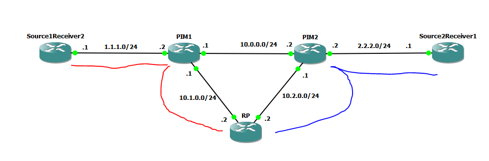
Once the first packet is received over the unicast tunnel from the source (PIM) to the RP, the RP would rather this traffic be delivered via multicast, so the RP sends a join message up the tree towards the source and has it's very own little Shortest Path Tree (SPT) back to the source, that's what this entry is:
一旦有第一个包从源(PIM)通过隧道发到RP,这个RP将让这个流量利用组播更好的传送,所以RP发送一个join消息指向树的源端,因此它有自己的到源的最短路径,就是下面的条目:
(1.1.1.1, 239.1.1.1), 00:03:59/00:02:03, flags: T
Incoming interface: GigabitEthernet1/0, RPF nbr 10.1.0.1
Outgoing interface list:
GigabitEthernet2/0, Forward/Sparse, 00:03:43/00:02:43
Then, a shared tree exists to the receiver PIM2:
然后,到PIM2有一个共享树:
(*, 239.1.1.1), 00:03:59/00:02:43, RP 3.3.3.3, flags: S
Incoming interface: Null, RPF nbr 0.0.0.0
Outgoing interface list:
GigabitEthernet2/0, Forward/Sparse, 00:03:43/00:02:43
So in the diagram above, the red line is the shortest path tree (SPT), the blue line is the shared tree.
所以在上面的图里,红线是最短路径树,蓝线是共享树
During all of this though, i noticed something strange....
在这个里面,我提一些陌生的内容....
When pinging the first time, all was well and i received a reply.. but when pinging a second time i received multiple responses...:
当我们第一次ping,都挺好,我收到了一个响应,但ping第二次的时候..
Source1Receiver2#ping 239.1.1.1
Type escape sequence to abort.
Sending 1, 100-byte ICMP Echos to 239.1.1.1, timeout is 2 seconds:
Reply to request 0 from 2.2.2.1, 172 ms
Source1Receiver2#ping 239.1.1.1
Type escape sequence to abort.
Sending 1, 100-byte ICMP Echos to 239.1.1.1, timeout is 2 seconds:
Reply to request 0 from 2.2.2.1, 100 ms
Reply to request 0 from 2.2.2.1, 120 ms
Why was i receiving two responses? I recalled from the excellent book (of which there are links to purchase from Amazon at the bottom of my post) that multicast has some general rules, for us here is the relevant one:
为什么我们收到两个响应,我从书里回想了一下组播的一些通用规则,在这就是其中的一个。
"When a new (S,G) entry is created, it's outgoing interface list is initially populated with a copy of the outgoing interface list from it's parent (,G) Entry"
当一个新的(S,G)条目产生,它的出接口列表是它父本(,G)条目出接口列表的复制而来的
A Ha! Let's look at the RP Routers multicast table:
让我们再看看RP组播表:
RP#show ip mroute
IP Multicast Routing Table
Flags: D - Dense, S - Sparse, B - Bidir Group, s - SSM Group, C - Connected,
L - Local, P - Pruned, R - RP-bit set, F - Register flag,
T - SPT-bit set, J - Join SPT, M - MSDP created entry, E - Extranet,
X - Proxy Join Timer Running, A - Candidate for MSDP Advertisement,
U - URD, I - Received Source Specific Host Report,
Z - Multicast Tunnel, z - MDT-data group sender,
Y - Joined MDT-data group, y - Sending to MDT-data group,
V - RD & Vector, v - Vector
Outgoing interface flags: H - Hardware switched, A - Assert winner
Timers: Uptime/Expires
Interface state: Interface, Next-Hop or VCD, State/Mode
(*, 239.1.1.1), 00:31:07/00:03:05, RP 3.3.3.3, flags: S
Incoming interface: Null, RPF nbr 0.0.0.0
Outgoing interface list:
GigabitEthernet2/0, Forward/Sparse, 00:30:52/00:03:05
(1.1.1.1, 239.1.1.1), 00:03:00/00:00:11, flags: T
Incoming interface: GigabitEthernet1/0, RPF nbr 10.1.0.1
Outgoing interface list:
GigabitEthernet2/0, Forward/Sparse, 00:03:00/00:03:05
So even though the Shortest Path Tree (SPT) is meant to end at the RP, it does not because the outgoing interface list for the (S,G) Entry (1.1.1.1,239.1.1.1) is copied from the (,G) Entry, which includes interface Gi2/0, hence why we receive two replies to our ping! Both Multicast entries are being used to route the packet, so a copy is being received twice.
因此即使SPT末端在RP,但它不是因为S,G的出接口列表复制于,G表项,包含了G2/0,因此这就是为什么我们收到两个回应,两个组播条目都被使用转发包,因此ping也被收到两次
事实上通过我做实验抓包分析,第一次ping是单播RP的PIM代理转发ICMP包
第二次ping是单播RP的PIM代理转发ICMP包和组播ICMP包两个这样的效果
如下图:

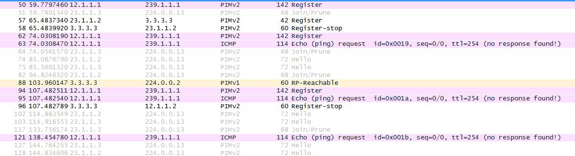

我认为他这个实验的目的就是想展示RP上会有两个组播条目,(*,G)的不会被PIM2修剪到的,因为PIM2只有共享树。
This is obviously not usual behavior and is simply a consequence of the fact that we have turned off the spt-threshold so that we don't use a proper, shortest path bridge.. so with that in mind, let's turn the spt-threshold back to the default.
这是明显不太常见的情况,只是一个关闭 spt-threshold 的简单结论,以至于我们关闭最短路径产生的现象,所以记住让我们把 spt-threshold 返回默认
RP(config)#no ip pim spt-threshold infinity
(Repeat on all routers)
Let's take a look what happens now when we generate some traffic to that multicast group.
让我们再生成一些流量看看发生什么
Source1Receiver2#ping 239.1.1.1
Type escape sequence to abort.
Sending 1, 100-byte ICMP Echos to 239.1.1.1, timeout is 2 seconds:
Reply to request 0 from 2.2.2.1, 60 ms
Source1Receiver2#ping 239.1.1.1
Type escape sequence to abort.
Sending 1, 100-byte ICMP Echos to 239.1.1.1, timeout is 2 seconds:
Reply to request 0 from 2.2.2.1, 64 ms
Source1Receiver2#ping 239.1.1.1
Type escape sequence to abort.
Sending 1, 100-byte ICMP Echos to 239.1.1.1, timeout is 2 seconds:
Reply to request 0 from 2.2.2.1, 60 ms
So we can see now.. one ping, one response, just like it should be, let's take a look at the multicast routing tables:
你可以看到,一个ping 一个回应,就应该这样。在看组播路由表:
PIM2#show ip mroute
IP Multicast Routing Table
Flags: D - Dense, S - Sparse, B - Bidir Group, s - SSM Group, C - Connected,
L - Local, P - Pruned, R - RP-bit set, F - Register flag,
T - SPT-bit set, J - Join SPT, M - MSDP created entry, E - Extranet,
X - Proxy Join Timer Running, A - Candidate for MSDP Advertisement,
U - URD, I - Received Source Specific Host Report,
Z - Multicast Tunnel, z - MDT-data group sender,
Y - Joined MDT-data group, y - Sending to MDT-data group,
V - RD & Vector, v - Vector
Outgoing interface flags: H - Hardware switched, A - Assert winner
Timers: Uptime/Expires
Interface state: Interface, Next-Hop or VCD, State/Mode
(*, 239.1.1.1), 00:01:11/stopped, RP 3.3.3.3, flags: SJC
Incoming interface: GigabitEthernet1/0, RPF nbr 10.2.0.2
Outgoing interface list:
GigabitEthernet2/0, Forward/Sparse, 00:01:11/00:02:51
(1.1.1.1, 239.1.1.1), 00:01:03/00:01:56, flags: JT
Incoming interface: GigabitEthernet3/0, RPF nbr 10.0.0.1
Outgoing interface list:
GigabitEthernet2/0, Forward/Sparse, 00:01:03/00:02:51
Check this out! You can see now that there is a (S,G) (remember, shortest path tree) for 1.1.1.1,239.1.1.1). The incoming interface is Gi3/0, which faces towards the PIM1 Router! So now our multicast traffic is NOT being sourced from the RP but rather we received a single frame from the RP, realised what the source is and therefore built a more effective tree.
看看,这个S,G入接口是G3/0指向PIM1的接口,现在我们的组播流量不在从RP接收,在RP也只是接,收一个帧,意识到组播源端后因此建立了更有效的树
This can be confirmed on router PIM1:
这个也PIM1能确认:
PIM1#show ip mroute
IP Multicast Routing Table
Flags: D - Dense, S - Sparse, B - Bidir Group, s - SSM Group, C - Connected,
L - Local, P - Pruned, R - RP-bit set, F - Register flag,
T - SPT-bit set, J - Join SPT, M - MSDP created entry, E - Extranet,
X - Proxy Join Timer Running, A - Candidate for MSDP Advertisement,
U - URD, I - Received Source Specific Host Report,
Z - Multicast Tunnel, z - MDT-data group sender,
Y - Joined MDT-data group, y - Sending to MDT-data group,
V - RD & Vector, v - Vector
Outgoing interface flags: H - Hardware switched, A - Assert winner
Timers: Uptime/Expires
Interface state: Interface, Next-Hop or VCD, State/Mode
(*, 239.1.1.1), 00:04:20/stopped, RP 3.3.3.3, flags: SPF
Incoming interface: GigabitEthernet2/0, RPF nbr 10.1.0.2
Outgoing interface list: Null
(1.1.1.1, 239.1.1.1), 00:01:15/00:02:14, flags: FT
Incoming interface: GigabitEthernet1/0, RPF nbr 0.0.0.0, Registering Outgoing interface list:
GigabitEthernet3/0, Forward/Sparse, 00:01:15/00:02:14
As you can see from the above output, we now have a SPT tree for the (S,G) 1.1.1.1, 239.1.1.1. it's incoming interface is as we expect, and the outgoing interface is now Gi3/0, so if we check out our diagram...
从上面的内容看,我们有个SPT树,它的入接口是我们想象到的,出接口则是G3/0

The yellow line shows our efficient multicast delivery, we only use the shared tree to learn the source of the multicast, once we know the source we create an SPT Tree back to it. This is known as the SPT-Switchover.
这个黄线就是有效的组播转发途径,我们只是使用共享树去学习组播源端,一旦源端被我们知道,SPT就是生成,这就是SPT切换。
Before we go any further you must be 100 percent confident with the above concepts, if you think it was complicated before.. you ain't seen nothing yet. Next we will look at Bidir PIM and source-specific multicast, but it's crucially important you understand the way the multicast traffic travels before we can explain the rest.
As I mentioned at the start of this little tutorial, I learnt all about multicast during my routing and switching CCIE, The most useful books for me during that period was the CCIE routing and switching exam certification guide, and specifically to multicast the Developing IP Multicast network book shown below, although it's a little bit of an older book, the guy who writes it peppers it with humor and wit, and the content is explained exceptionally well, if I learnt to understand multicast with it anyone should be able to. It's a great book, if you enjoyed this blog post and found it useful, please consider purchasing it from one of the links below 😃

 浙公网安备 33010602011771号