

2.rt-thread标准版配置串口(中断接收)(基于RT-Thread-Studio)
目录
rt-thread标准版配置串口(基于RT-Thread-Studio)
1 配置串口示例
board.h中的注释
/** After configuring corresponding UART or UART DMA, you can use it.
 *
 * STEP 1, define macro define related to the serial port opening based on the serial port number
 *                 such as     #define BSP_USING_UART1
 *
 * STEP 2, according to the corresponding pin of serial port, define the related serial port information macro
 *                 such as     #define BSP_UART1_TX_PIN       "PA9"
 *                             #define BSP_UART1_RX_PIN       "PA10"
 *
 * STEP 3, if you want using SERIAL DMA, you must open it in the RT-Thread Settings.
 *                 RT-Thread Setting -> Components -> Device Drivers -> Serial Device Drivers -> Enable Serial DMA Mode
 *
 * STEP 4, according to serial port number to define serial port tx/rx DMA function in the board.h file
 *                 such as     #define BSP_UART1_RX_USING_DMA
1. 第一步:首先在board.h中宏定义
-->board.h

#define BSP_USING_UART2
#define BSP_UART2_TX_PIN       "PA2"
#define BSP_UART2_RX_PIN       "PA3"

//配置DMA模式使用
//#define BSP_UART2_TX_USING_DMA
//#define BSP_UART2_RX_USING_DMA
2. 第二步:获取设备句柄
-->main.c

static rt_device_t test_serial;
test_serial = rt_device_find("uart2");
3. 第三步:打开设备
-->rtdef.h
//===============
#define RT_DEVICE_OFLAG_RDONLY          0x001           /**< read only access */
#define RT_DEVICE_OFLAG_WRONLY          0x002           /**< write only access */
#define RT_DEVICE_OFLAG_RDWR            0x003           /**< read and write */

#define RT_DEVICE_FLAG_INT_RX           0x100           /**< INT mode on Rx */
#define RT_DEVICE_FLAG_DMA_RX           0x200           /**< DMA mode on Rx */
#define RT_DEVICE_FLAG_INT_TX           0x400           /**< INT mode on Tx */
#define RT_DEVICE_FLAG_DMA_TX           0x800           /**< DMA mode on Tx */
//===============

-->main.c
//===============
//读写模式,中断接收,轮询发送
rt_device_open(test_serial,
               RT_DEVICE_OFLAG_RDWR
             | RT_DEVICE_FLAG_INT_RX);
4. 第四步:配置串口参数
-->serial.h
//=============

struct serial_configure//可定义结构体,按照下面格式定义就可以

//默认参数
/* Default config for serial_configure structure */
#define RT_SERIAL_CONFIG_DEFAULT           \
{                                          \
    BAUD_RATE_115200, /* 115200 bits/s */  \
    DATA_BITS_8,      /* 8 databits */     \
    STOP_BITS_1,      /* 1 stopbit */      \
    PARITY_NONE,      /* No parity  */     \
    BIT_ORDER_LSB,    /* LSB first sent */ \
    NRZ_NORMAL,       /* Normal mode */    \
    RT_SERIAL_RB_BUFSZ, /* Buffer size */  \
    0                                      \
}
//===========
-->main.c

struct serial_configure uart2_set_parg={   \
    BAUD_RATE_115200, /* 115200 bits/s */  \
    DATA_BITS_8,      /* 8 databits */     \
    STOP_BITS_1,      /* 1 stopbit */      \
    PARITY_NONE,      /* No parity  */     \
    BIT_ORDER_LSB,    /* LSB first sent */ \
    NRZ_NORMAL,       /* Normal mode */    \
    RT_SERIAL_RB_BUFSZ, /* Buffer size */  \
    0                                      \
};

rt_device_control(test_serial, RT_DEVICE_CTRL_CONFIG, &uart2_set_parg);
5. 第五步:有需要设置接收/发送回调函数
-->mian.c
//如果设置的是中断/DMA可以设置回调函数

rt_err_t rt_device_set_tx_complete(rt_device_t dev, rt_err_t (*tx_done)(rt_device_t dev,void *buffer));
/*用程序调用 rt_device_write() 写入数据时,如果底层硬件能够支持自动发送,
那么上层应用可以设置一个回调函数。
这个回调函数会在底层硬件数据发送完成后 (例如 DMA 传送完成或 FIFO 已经写入完毕产生完成中断时) 调用。
调用个函数时,回调函数由调用者提供,当硬件设备发送完数据时,由设备驱动程序回调这个函数并把发送完成的数据块地址 buffer 作为参数传递给上层应用。上层应用(线程)在收到指示时会根据发送 buffer 的情况,释放 buffer 内存块或将其作为下一个写数据的缓存。*/

rt_err_t rt_device_set_rx_indicate(rt_device_t dev, rt_err_t (*rx_ind)(rt_device_t dev,rt_size_t size));

/*
该函数的回调函数由调用者提供。
若串口以中断接收模式打开,当串口接收到一个数据产生中断时,就会调用回调函数,并且会把此时缓冲区的数据大小放在 size 参数里,把串口设备句柄放在 dev 参数里供调用者获取。

若串口以 DMA 接收模式打开,当 DMA 完成一批数据的接收后会调用此回调函数。*/

uint16_t count;
uint8_t test_buff[10];
rt_err_t rx_irq(rt_device_t dev,rt_size_t size)
{
    rt_kprintf("count:%d",count++);
    if(count == 10)
    {
        count=0;
        rt_device_write(test_serial, 0, "receive 10 bytes!", strlen("receive 10 bytes!"));
        rt_device_read(test_serial, 0, test_buff, 10);//读一次清除内部环形缓冲区
    }
    return 0;
}

rt_device_set_rx_indicate(test_serial, rx_irq);
6. 第六步:使用 rt_device_write/rt_device_read 读取或者写入数据
7. 源代码示例
board.h
/*
 * Copyright (c) 2006-2025, RT-Thread Development Team
 *
 * SPDX-License-Identifier: Apache-2.0
 *
 * Change Logs:
 * Date           Author       Notes
 * 2025-03-23     RealThread   first version
 */

#ifndef __BOARD_H__
#define __BOARD_H__

#include <stm32f1xx.h>
#include <drv_common.h>

#ifdef __cplusplus
extern "C"
{
#endif

/*-------------------------- CHIP CONFIG BEGIN --------------------------*/

#define CHIP_FAMILY_STM32
#define CHIP_SERIES_STM32F1
#define CHIP_NAME_STM32F103ZE

/*-------------------------- CHIP CONFIG END --------------------------*/

/*-------------------------- ROM/RAM CONFIG BEGIN --------------------------*/

#define ROM_START              ((uint32_t)0x08000000)
#define ROM_SIZE               (512 * 1024)
#define ROM_END                ((uint32_t)(ROM_START + ROM_SIZE))

#define RAM_START              (0x20000000)
#define RAM_SIZE               (64 * 1024)
#define RAM_END                (RAM_START + RAM_SIZE)

/*-------------------------- ROM/RAM CONFIG END --------------------------*/

/*-------------------------- CLOCK CONFIG BEGIN --------------------------*/

#define BSP_CLOCK_SOURCE                  ("HSE")
#define BSP_CLOCK_SOURCE_FREQ_MHZ         ((int32_t)8)
#define BSP_CLOCK_SYSTEM_FREQ_MHZ         ((int32_t)72)

/*-------------------------- CLOCK CONFIG END --------------------------*/

/*-------------------------- UART CONFIG BEGIN --------------------------*/

/** After configuring corresponding UART or UART DMA, you can use it.
 *
 * STEP 1, define macro define related to the serial port opening based on the serial port number
 *                 such as     #define BSP_USING_UART1
 *
 * STEP 2, according to the corresponding pin of serial port, define the related serial port information macro
 *                 such as     #define BSP_UART1_TX_PIN       "PA9"
 *                             #define BSP_UART1_RX_PIN       "PA10"
 *
 * STEP 3, if you want using SERIAL DMA, you must open it in the RT-Thread Settings.
 *                 RT-Thread Setting -> Components -> Device Drivers -> Serial Device Drivers -> Enable Serial DMA Mode
 *
 * STEP 4, according to serial port number to define serial port tx/rx DMA function in the board.h file
 *                 such as     #define BSP_UART1_RX_USING_DMA
 *
 */

#define BSP_USING_UART1
#define BSP_UART1_TX_PIN       "PA9"
#define BSP_UART1_RX_PIN       "PA10"


#define BSP_USING_UART2
#define BSP_UART2_TX_PIN       "PA2"
#define BSP_UART2_RX_PIN       "PA3"


/*-------------------------- UART CONFIG END --------------------------*/

/*-------------------------- I2C CONFIG BEGIN --------------------------*/

/** if you want to use i2c bus(soft simulate) you can use the following instructions.
 *
 * STEP 1, open i2c driver framework(soft simulate) support in the RT-Thread Settings file
 *
 * STEP 2, define macro related to the i2c bus
 *                 such as     #define BSP_USING_I2C1
 *
 * STEP 3, according to the corresponding pin of i2c port, modify the related i2c port and pin information
 *                 such as     #define BSP_I2C1_SCL_PIN    GET_PIN(port, pin)   ->   GET_PIN(C, 11)
 *                             #define BSP_I2C1_SDA_PIN    GET_PIN(port, pin)   ->   GET_PIN(C, 12)
 */

/*#define BSP_USING_I2C1*/
#ifdef BSP_USING_I2C1
#define BSP_I2C1_SCL_PIN    GET_PIN(port, pin)
#define BSP_I2C1_SDA_PIN    GET_PIN(port, pin)
#endif

/*#define BSP_USING_I2C2*/
#ifdef BSP_USING_I2C2
#define BSP_I2C2_SCL_PIN    GET_PIN(port, pin)
#define BSP_I2C2_SDA_PIN    GET_PIN(port, pin)
#endif

/*-------------------------- I2C CONFIG END --------------------------*/

/*-------------------------- SPI CONFIG BEGIN --------------------------*/

/** if you want to use spi bus you can use the following instructions.
 *
 * STEP 1, open spi driver framework support in the RT-Thread Settings file
 *
 * STEP 2, define macro related to the spi bus
 *                 such as     #define BSP_USING_SPI1
 *
 * STEP 3, copy your spi init function from stm32xxxx_hal_msp.c generated by stm32cubemx to the end of board.c file
 *                 such as     void HAL_SPI_MspInit(SPI_HandleTypeDef* hspi)
 *
 * STEP 4, modify your stm32xxxx_hal_config.h file to support spi peripherals. define macro related to the peripherals
 *                 such as     #define HAL_SPI_MODULE_ENABLED
 */

/*#define BSP_USING_SPI1*/
/*#define BSP_USING_SPI2*/
/*#define BSP_USING_SPI3*/

/*-------------------------- SPI CONFIG END --------------------------*/

/*-------------------------- QSPI CONFIG BEGIN --------------------------*/

/** if you want to use qspi you can use the following instructions.
 *
 * STEP 1, open qspi driver framework support in the RT-Thread Settings file
 *
 * STEP 2, define macro related to the qspi
 *                 such as     #define BSP_USING_QSPI
 *
 * STEP 3, copy your qspi init function from stm32xxxx_hal_msp.c generated by stm32cubemx to the end of board.c file
 *                 such as     void HAL_QSPI_MspInit(QSPI_HandleTypeDef* hqspi)
 *
 * STEP 4, modify your stm32xxxx_hal_config.h file to support qspi peripherals. define macro related to the peripherals
 *                 such as     #define HAL_QSPI_MODULE_ENABLED
 *
 */

/*#define BSP_USING_QSPI*/

/*-------------------------- QSPI CONFIG END --------------------------*/

/*-------------------------- PWM CONFIG BEGIN --------------------------*/

/** if you want to use pwm you can use the following instructions.
 *
 * STEP 1, open pwm driver framework support in the RT-Thread Settings file
 *
 * STEP 2, define macro related to the pwm
 *                 such as     #define BSP_USING_PWM1
 *
 * STEP 3, copy your pwm timer init function from stm32xxxx_hal_msp.c generated by stm32cubemx to the end if board.c file
 *                 such as     void HAL_TIM_Base_MspInit(TIM_HandleTypeDef* htim_base)  and
 *                             void HAL_TIM_MspPostInit(TIM_HandleTypeDef* htim)
 *
 * STEP 4, modify your stm32xxxx_hal_config.h file to support pwm peripherals. define macro related to the peripherals
 *                 such as     #define HAL_TIM_MODULE_ENABLED
 *
 */

/*#define BSP_USING_PWM1*/
/*#define BSP_USING_PWM2*/
/*#define BSP_USING_PWM3*/

/*-------------------------- PWM CONFIG END --------------------------*/

/*-------------------------- ADC CONFIG BEGIN --------------------------*/

/** if you want to use adc you can use the following instructions.
 *
 * STEP 1, open adc driver framework support in the RT-Thread Settings file
 *
 * STEP 2, define macro related to the adc
 *                 such as     #define BSP_USING_ADC1
 *
 * STEP 3, copy your adc init function from stm32xxxx_hal_msp.c generated by stm32cubemx to the end of board.c file
 *                 such as     void HAL_ADC_MspInit(ADC_HandleTypeDef* hadc)
 *
 * STEP 4, modify your stm32xxxx_hal_config.h file to support adc peripherals. define macro related to the peripherals
 *                 such as     #define HAL_ADC_MODULE_ENABLED
 *
 */

/*#define BSP_USING_ADC1*/
/*#define BSP_USING_ADC2*/
/*#define BSP_USING_ADC3*/

/*-------------------------- ADC CONFIG END --------------------------*/

/*-------------------------- WDT CONFIG BEGIN --------------------------*/

/** if you want to use wdt you can use the following instructions.
 *
 * STEP 1, open wdt driver framework support in the RT-Thread Settings file
 *
 * STEP 2, modify your stm32xxxx_hal_config.h file to support wdt peripherals. define macro related to the peripherals
 *                 such as     #define HAL_IWDG_MODULE_ENABLED
 *
 */

/*-------------------------- WDT CONFIG END --------------------------*/

/*-------------------------- HARDWARE TIMER CONFIG BEGIN --------------------------*/

/** if you want to use hardware timer you can use the following instructions.
 *
 * STEP 1, open hwtimer driver framework support in the RT-Thread Settings file
 *
 * STEP 2, define macro related to the hwtimer
 *                 such as     #define BSP_USING_TIM  and
 *                             #define BSP_USING_TIM1
 *
 * STEP 3, copy your hardwire timer init function from stm32xxxx_hal_msp.c generated by stm32cubemx to the end of board.c file
 *                 such as     void HAL_TIM_Base_MspInit(TIM_HandleTypeDef* htim_base)
 *
 * STEP 4, modify your stm32xxxx_hal_config.h file to support hardwere timer peripherals. define macro related to the peripherals
 *                 such as     #define HAL_TIM_MODULE_ENABLED
 *
 */

/*#define BSP_USING_TIM*/
#ifdef BSP_USING_TIM
/*#define BSP_USING_TIM15*/
/*#define BSP_USING_TIM16*/
/*#define BSP_USING_TIM17*/
#endif

/*-------------------------- HAREWARE TIMER CONFIG END --------------------------*/

/*-------------------------- RTC CONFIG BEGIN --------------------------*/

/** if you want to use rtc(hardware) you can use the following instructions.
 *
 * STEP 1, open rtc driver framework(hardware) support in the RT-Thread Settings file
 *
 * STEP 2, define macro related to the rtc
 *                 such as    BSP_USING_ONCHIP_RTC
 *
 * STEP 3, modify your stm32xxxx_hal_config.h file to support rtc peripherals. define macro related to the peripherals
 *                 such as     #define HAL_RTC_MODULE_ENABLED
 *
 */
/*#define BSP_USING_ONCHIP_RTC*/

/*-------------------------- RTC CONFIG END --------------------------*/

/*-------------------------- SDIO CONFIG BEGIN --------------------------*/

/** if you want to use sdio you can use the following instructions.
 *
 * STEP 1, open sdio driver framework support in the RT-Thread Settings file
 *
 * STEP 2, define macro related to the sdio
 *                 such as    BSP_USING_SDIO
 *
 * STEP 3, copy your sdio init function from stm32xxxx_hal_msp.c generated by stm32cubemx to the end of board.c file
 *                 such as     void HAL_SD_MspInit(SD_HandleTypeDef* hsd)
 *
 * STEP 4, modify your stm32xxxx_hal_config.h file to support sdio peripherals. define macro related to the peripherals
 *                 such as     #define HAL_SD_MODULE_ENABLED
 *
 * STEP 5, config your device file system or another applications
 *
 */

/*#define BSP_USING_SDIO*/

/*-------------------------- SDIO CONFIG END --------------------------*/

/*-------------------------- ETH CONFIG BEGIN --------------------------*/

/** if you want to use eth you can use the following instructions.
 *
 * STEP 1, define macro related to the eth
 *                 such as    BSP_USING_ETH
 *
 * STEP 2, copy your eth init function from stm32xxxx_hal_msp.c generated by stm32cubemx to the end if board.c file
 *                 such as     void HAL_ETH_MspInit(ETH_HandleTypeDef* heth)
 *
 * STEP 3, modify your stm32xxxx_hal_config.h file to support eth peripherals. define macro related to the peripherals
 *                 such as     #define HAL_ETH_MODULE_ENABLED
 *
 * STEP 4, config your phy type
 *                 such as     #define PHY_USING_LAN8720A
 *                             #define PHY_USING_DM9161CEP
 *                             #define PHY_USING_DP83848C
 * STEP 5, implement your phy reset function in the end of board.c file
 *                 void phy_reset(void)
 *
 * STEP 6, config your lwip or other network stack
 *
 */

/*#define BSP_USING_ETH*/
#ifdef BSP_USING_ETH
/*#define PHY_USING_LAN8720A*/
/*#define PHY_USING_DM9161CEP*/
/*#define PHY_USING_DP83848C*/
#endif
/*-------------------------- ETH CONFIG END --------------------------*/

/*-------------------------- USB HOST CONFIG BEGIN --------------------------*/

/** if you want to use usb host you can use the following instructions.
 *
 * STEP 1, open usb host driver framework support in the RT-Thread Settings file
 *
 * STEP 2, define macro related to the usb host
 *                 such as    BSP_USING_USBHOST
 *
 * STEP 3, copy your usb host init function from stm32xxxx_hal_msp.c generated by stm32cubemx to the end of board.c file
 *                 such as     void HAL_HCD_MspInit(HCD_HandleTypeDef* hhcd)
 *
 * STEP 4, config your usb peripheral clock in SystemClock_Config() generated by STM32CubeMX and replace this function in board.c
 *
 * STEP 5, modify your stm32xxxx_hal_config.h file to support usb host peripherals. define macro related to the peripherals
 *                 such as     #define HAL_HCD_MODULE_ENABLED
 *
 */

/*#define BSP_USING_USBHOST*/

/*-------------------------- USB HOST CONFIG END --------------------------*/

/*-------------------------- USB DEVICE CONFIG BEGIN --------------------------*/

/** if you want to use usb device you can use the following instructions.
 *
 * STEP 1, open usb device driver framework support in the RT-Thread Settings file
 *
 * STEP 2 define macro related to the usb device
 *                 such as    BSP_USING_USBDEVICE
 *
 * STEP 3, copy your usb device init function from stm32xxxx_hal_msp.c generated by stm32cubemx to the end of board.c file
 *                 such as     void HAL_PCD_MspInit(PCD_HandleTypeDef* hpcd)
 *
 * STEP 4, config your usb peripheral clock in SystemClock_Config() generated by STM32CubeMX and replace this function in board.c
 *
 * STEP 5, modify your stm32xxxx_hal_config.h file to support usb device peripherals. define macro related to the peripherals
 *                 such as     #define HAL_PCD_MODULE_ENABLED
 *
 */

/*#define BSP_USING_USBDEVICE*/

/*-------------------------- USB DEVICE CONFIG END --------------------------*/

/*-------------------------- ON_CHIP_FLASH CONFIG BEGIN --------------------------*/

/** if you want to use on chip flash you can use the following instructions.
 *
 * STEP 1 define macro related to the on chip flash
 *                 such as    BSP_USING_ON_CHIP_FLASH
 *
 * STEP 2, modify your stm32xxxx_hal_config.h file to support on chip flash peripherals. define macro related to the peripherals
 *                 such as     #define HAL_FLASH_MODULE_ENABLED
 *
 */

/*#define BSP_USING_ON_CHIP_FLASH*/

/*-------------------------- ON_CHIP_FLASH CONFIG END --------------------------*/

#ifdef __cplusplus
}
#endif

#endif /* __BOARD_H__ */
main.c
/*
 * Copyright (c) 2006-2025, RT-Thread Development Team
 *
 * SPDX-License-Identifier: Apache-2.0
 *
 * Change Logs:
 * Date           Author       Notes
 * 2025-03-21     RT-Thread    first version
 */

#include <rtthread.h>

#define DBG_TAG "main"
#define DBG_LVL DBG_LOG
#include <rtdbg.h>
#include <stm32f1xx.h>
#include "rtdevice.h"
#include "board.h"
#define LED1_PIN    GET_PIN(B,5)//亮为低电平
#define LED2_PIN    GET_PIN(E,5)//亮为低电平

#define WAKE_PIN    GET_PIN(A,0)//唤醒按钮
#define KEY1_PIN    GET_PIN(E,4) //触发为高电平
#define KEY2_PIN    GET_PIN(E,3) //触发为高电平

static rt_device_t test_serial;

uint16_t count;
uint8_t test_buff[10];
rt_err_t rx_irq(rt_device_t dev,rt_size_t size)
{
    rt_kprintf("count:%d",count++);
    if(count == 10)
    {
        count=0;
        rt_device_write(test_serial, 0, "receive 10 bytes!", strlen("receive 10 bytes!"));
        rt_device_read(test_serial, 0, test_buff, 10);//读一次清除内部环形缓冲区
    }
    return 0;
}


int main(void)
{
    LOG_D("System Clock information");
    LOG_D("SYSCLK_Frequency = %d", HAL_RCC_GetSysClockFreq());
    LOG_D("HCLK_Frequency = %d", HAL_RCC_GetHCLKFreq());
    LOG_D("PCLK1_Frequency = %d", HAL_RCC_GetPCLK1Freq());
    LOG_D("PCLK2_Frequency = %d", HAL_RCC_GetPCLK2Freq());


    /* 配置推挽输出 */
    rt_pin_mode(LED1_PIN, PIN_MODE_OUTPUT);

    test_serial = rt_device_find("uart2");
    rt_device_open(test_serial,
                   RT_DEVICE_OFLAG_RDWR
                 | RT_DEVICE_FLAG_INT_RX);
    struct serial_configure uart2_set_parg={   \
        BAUD_RATE_115200, /* 115200 bits/s */  \
        DATA_BITS_8,      /* 8 databits */     \
        STOP_BITS_1,      /* 1 stopbit */      \
        PARITY_NONE,      /* No parity  */     \
        BIT_ORDER_LSB,    /* LSB first sent */ \
        NRZ_NORMAL,       /* Normal mode */    \
        RT_SERIAL_RB_BUFSZ, /* Buffer size */  \
        0                                      \
    };
    rt_device_control(test_serial, RT_DEVICE_CTRL_CONFIG, &uart2_set_parg);

    rt_device_set_rx_indicate(test_serial, rx_irq);


    while (1)
    {
        /* LED闪烁 */
        rt_pin_write(LED1_PIN, !rt_pin_read(LED1_PIN));

        /* 线程轮询时间 */
        rt_thread_mdelay(500);

    }

    return RT_EOK;
}
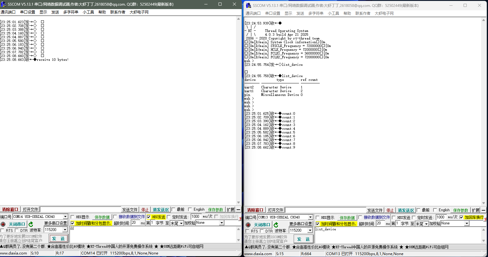
8. 实验结果

 浙公网安备 33010602011771号