
33、HCIP综合实验
一、总公司规划


拓扑图

二、公司总部内部网络
1、交换机SW1、2、3、4上vlan配置
创建vlan
sys
un in en
sys SW1
vlan batch 10 20 30 40 200
放行vlan
# SW1和SW2上
port-group group-member g0/0/3 to g0/0/5
port link-type trunk
port trunk allow-pass vlan 10 20 30 40 200
# SW3和SW4上
port-group group-member g0/0/1 to g0/0/3
port link-type trunk
port trunk allow-pass vlan 10 20 30 40 200
SW3和SW4上,将下行口加入vlan
# SW3
interface GigabitEthernet0/0/4
 port link-type trunk
 # 打上业务vlan的vlan tag
 port trunk pvid vlan 200
 port trunk allow-pass vlan 10 20 200

# SW4
interface GigabitEthernet0/0/4
 port link-type access
 port default vlan 30
interface GigabitEthernet0/0/5
 port link-type access
 port default vlan 40
2、交换机上配置MSTP和VRRP
配置MSTP
# SW1、2、3、4
stp region-configuration
 region-name 1
 instance 1 vlan 10 20
 instance 2 vlan 30 40
 active region-configuration
# SW1
stp instance 1 root primary
stp instance 2 root secondary
# SW2
stp instance 1 root secondary
stp instance 2 root primary
验证MSTP配置
dis stp brief


配置VRRP
- vrid1、2、3、4分别对应vlan10、20、30、40
- SW1为vrid1、2的主3、4的备。
- SW2为vrid1、2的备3、4的主。
# SW1上
interface Vlanif10
 ip address 10.0.10.252 255.255.255.0
 vrrp vrid 1 virtual-ip 10.0.10.254
 vrrp vrid 1 priority 120
interface Vlanif20
 ip address 10.0.20.252 255.255.255.0
 vrrp vrid 2 virtual-ip 10.0.20.254
 vrrp vrid 2 priority 120
interface Vlanif30
 ip address 10.0.30.252 255.255.255.0
 vrrp vrid 3 virtual-ip 10.0.30.254
interface Vlanif40
 ip address 10.0.40.252 255.255.255.0
 vrrp vrid 4 virtual-ip 10.0.40.254


# SW2上
interface Vlanif10
 ip address 10.0.10.253 255.255.255.0
 vrrp vrid 1 virtual-ip 10.0.10.254
interface Vlanif20
 ip address 10.0.20.253 255.255.255.0
 vrrp vrid 2 virtual-ip 10.0.20.254
interface Vlanif30
 ip address 10.0.30.253 255.255.255.0
 vrrp vrid 3 virtual-ip 10.0.30.254
 vrrp vrid 3 priority 120
interface Vlanif40
 ip address 10.0.40.253 255.255.255.0
 vrrp vrid 4 virtual-ip 10.0.40.254
 vrrp vrid 4 priority 120
验证VRRP配置
dis vrrp brief


3、配置AC
SW1配置于AC相连的接口
interface GigabitEthernet0/0/6
 port link-type access
 port default vlan 200
AC上配置vlan和dhcp
vlan batch 10 20 200
interface GigabitEthernet0/0/1
 port link-type access
 port default vlan 200
dhcp enable
interface Vlanif200
 ip address 10.0.200.254 255.255.255.0
 dhcp select interface
查看dhcp地址池
dis ip pool

配置AP上线
[AC1]capwap source interface Vlanif 200
[AC1]wlan
# 使用mac地址绑定(需要先去将ap的mac地址复制过来)
[AC1-wlan-view]ap-id 0 ap-mac 00e0-fcdd-6740
[AC1-wlan-ap-0]ap-name AP1
[AC1-wlan-ap-0]q
[AC1-wlan-view]q
# 配置ssid
[AC1]wlan
[AC1-wlan-view]ssid-profile name 1
[AC1-wlan-ssid-prof-1]ssid hcip-datacom
[AC1-wlan-ssid-prof-1]q
# 配置安全模板
[AC1-wlan-view]security-profile name 1
# 密码
[AC1-wlan-sec-prof-1]security wpa-wpa2 psk pass-phrase huawei123 aes
[AC1-wlan-sec-prof-1]q
[AC1-wlan-view]q
# 创建vlan池
[AC1]vlan pool 1
[AC1-vlan-pool-1]vlan 10 20
[AC1-vlan-pool-1]q
# 配置vap模板
[AC1]wlan
[AC1-wlan-view]vap-profile name 1
[AC1-wlan-vap-prof-1]service-vlan vlan-pool 1
[AC1-wlan-vap-prof-1]ssid-profile 1
[AC1-wlan-vap-prof-1]security-profile 1
[AC1-wlan-vap-prof-1]q


[AC1-wlan-view]ap-group name 1
[AC1-wlan-ap-group-1]vap-profile 1 wlan 1 radio 0
[AC1-wlan-ap-group-1]q
[AC1-wlan-view]ap-id 0
[AC1-wlan-ap-0]ap-group 1
4、配置防火墙与交换机之间的链路聚合
将防火墙超时时间配置为永不超时
# 防火墙密码更改为了Huawei@123
[FW1]un in en
[FW1]user-interface console 0
[FW1-ui-console0]idle-timeout 0
防火墙FW1上
[FW1]interface  Eth-Trunk 1
[FW1-Eth-Trunk1]portswitch
[FW1-Eth-Trunk1]mode lacp-static
[FW1-Eth-Trunk1]trunkport g1/0/1
[FW1-Eth-Trunk1]trunkport g1/0/2

[FW1]int Eth-Trunk 2
[FW1-Eth-Trunk2]portswitch
[FW1-Eth-Trunk2]mode lacp-static
[FW1-Eth-Trunk2]trunkport g1/0/3
[FW1-Eth-Trunk2]trunkport g1/0/4
SW1上
int Eth-Trunk 1
portswitch
mode lacp-static
trunkport g0/0/1
trunkport g0/0/2
SW2上
interface Eth-Trunk 1
portswitch
mode lacp-static
trunkport g0/0/1
trunkport g0/0/2
查看聚合口状态
dis eth-trunk

5、配置聚合口的vlan以及vlanif
防火墙
vlan batch 100 101
interface Eth-Trunk1
 port link-type trunk
 port trunk allow-pass vlan 100
interface Eth-Trunk2
 port link-type trunk
 port trunk allow-pass vlan 101

interface Vlanif100
 ip address 10.0.100.1 255.255.255.0
interface Vlanif101
 ip address 10.0.101.1 255.255.255.0
SW1、2
# SW1
vlan batch 100
interface Eth-Trunk1
 port link-type trunk
 port trunk allow-pass vlan 100
interface Vlanif100
 ip address 10.0.100.2 255.255.255.0

# SW2
vlan batch 101
interface Eth-Trunk1
 port link-type trunk
 port trunk allow-pass vlan 101
interface Vlanif101
 ip address 10.0.101.2 255.255.255.0
6、配置DHCP和DHCP中继
防火墙上配置IP地址池
ip pool vlan10
 gateway-list 10.0.10.254
 network 10.0.10.0 mask 255.255.255.0
ip pool vlan20
 gateway-list 10.0.20.254
 network 10.0.20.0 mask 255.255.255.0
ip pool vlan30
 gateway-list 10.0.30.254
 network 10.0.30.0 mask 255.255.255.0
ip pool vlan40
 gateway-list 10.0.40.254
 network 10.0.40.0 mask 255.255.255.0
防火墙上开启DHCP
dhcp enable
interface Vlanif100
 dhcp select global
interface Vlanif101
 dhcp select global
防火墙上将vlanif100和101配置到trust区域
firewall zone trust
 add interface Vlanif100
 add interface Vlanif101
SW1和SW2上配置DHCP中继
# SW1
dhcp enable

interface Vlanif10
 dhcp select relay
 dhcp relay server-ip 10.0.100.1
interface Vlanif20
 dhcp select relay
 dhcp relay server-ip 10.0.100.1
interface Vlanif30
 dhcp select relay
 dhcp relay server-ip 10.0.100.1
interface Vlanif40
 dhcp select relay
 dhcp relay server-ip 10.0.100.1


# SW2
dhcp enable
interface Vlanif10
 dhcp select relay
 dhcp relay server-ip 10.0.101.1
interface Vlanif20
 dhcp select relay
 dhcp relay server-ip 10.0.101.1
interface Vlanif30
 dhcp select relay
 dhcp relay server-ip 10.0.101.1
interface Vlanif40
 dhcp select relay
 dhcp relay server-ip 10.0.101.1
由于防火墙没有下方10.0.10、20、30、40网段的路由,所以下方PC仍然无法通过DHCP获取到IP。
7、防火墙和交换机之间配置OSPF
防火墙
ospf 1
 area 0.0.0.0
  network 10.0.100.0 0.0.0.255
  network 10.0.101.0 0.0.0.255
SW1
ospf 1
 silent-interface Vlanif10
 silent-interface Vlanif20
 silent-interface Vlanif30
 silent-interface Vlanif40
 area 0.0.0.0
  network 10.0.10.0 0.0.0.255
  network 10.0.20.0 0.0.0.255
  network 10.0.30.0 0.0.0.255
  network 10.0.40.0 0.0.0.255
  network 10.0.100.0 0.0.0.255
SW2
ospf 1
 silent-interface Vlanif10
 silent-interface Vlanif20
 silent-interface Vlanif30
 silent-interface Vlanif40
 area 0.0.0.0
  network 10.0.10.0 0.0.0.255
  network 10.0.20.0 0.0.0.255
  network 10.0.30.0 0.0.0.255
  network 10.0.40.0 0.0.0.255
  network 10.0.101.0 0.0.0.255
在PC上查看IP地址,验证DHCP和OSPF配置是否成功

8、防火墙与CE之间的配置
配置防火墙的上行接口,并允许OSPF
# 清除原有的默认配置,并配置IP地址
[FW1]int g0/0/0
[FW1-GigabitEthernet0/0/0]undo ip binding vpn-instance default
[FW1-GigabitEthernet0/0/0]ip add 10.0.11.1 24

interface GigabitEthernet1/0/0
 ip address 10.0.12.1 255.255.255.0

# 划分区域
# 先将g0/0/0移出trust区域
[FW1]firewall zone trust
[FW1-zone-trust]undo add interface g0/0/0

firewall zone untrust
 add interface GigabitEthernet0/0/0
 add interface GigabitEthernet1/0/0
配置CE1的IP
sys
sys CE1
int g0/0/0
ip add 64.1.1.2 24
int g0/0/1
ip add 66.1.1.2 24
int g0/0/2
ip add 10.0.11.2 24
配置CE2的IP
sys
sys CE2
int g0/0/0
ip add 65.1.1.2 24
int g0/0/1
ip add 67.1.1.2 24
int g0/0/2
ip add 10.0.12.2 24
运行OSPF
# FW1(总公司的SW1、SW2、FW1、以及CE1和CE2的g0/0/2都运行OSPF,且都在区域0中)
ospf 1
 area 0.0.0.0
  network 10.0.11.0 0.0.0.255
  network 10.0.12.0 0.0.0.255

# CE1
ospf 1
 area 0.0.0.0
  network 10.0.11.0 0.0.0.255

# CE2
ospf 1
 area 0.0.0.0
  network 10.0.12.0 0.0.0.255
CE与公网之间不需要跑OSPF,可以将对应的接口设置为静默接口。
查看OSPF邻居,验证配置
dis ospf peer brief

三、分公司内部网络
1、SW7、8、9上配置vlan,RSTP
在SW7、8、9上创建valn
# 以SW7为例
sys
un in en
sys SW7
vlan batch 50 60
放行端口
# SW7
[SW7]port-group group-member g0/0/2 g0/0/3
[SW7-port-group]p l t
[SW7-GigabitEthernet0/0/2]p l t
[SW7-GigabitEthernet0/0/3]p l t
[SW7-port-group]p t a v 50 60
[SW7-GigabitEthernet0/0/2]p t a v 50 60
[SW7-GigabitEthernet0/0/3]p t a v 50 60

# SW8
port-group group-member g0/0/1 g0/0/2
p l t
p t a v 50 60
q

interface GigabitEthernet0/0/3
 port link-type access
 port default vlan 50

# SW9
port-group group-member g0/0/1 g0/0/2
p l t
p t a v 50 60
q

interface GigabitEthernet0/0/3
 port link-type access
 port default vlan 60
配置RSTP
# SW7
stp mode rstp
# 顺便把SW7设为根
stp root primary

# SW8
stp mode rstp
int g0/0/3
stp edged-port enable

# SW9
stp mode rstp
int g0/0/3
stp edged-port enable
验证RSTP配置
dis stp brief

2、配置DHCP
SW7
dhcp enable
interface Vlanif50
 ip address 10.0.50.254 255.255.255.0
 dhcp select interface
interface Vlanif60
 ip address 10.0.60.254 255.255.255.0
 dhcp select interface
在PC上查看IP地址,验证DHCP是否配置成功

3、SW7与CE3之间的配置
SW7
interface Vlanif1
 ip address 10.0.37.7 255.255.255.0
ospf 1
 area 0.0.0.0
  network 10.0.37.0 0.0.0.255
  network 10.0.50.0 0.0.0.255
  network 10.0.60.0 0.0.0.255
CE3
sys
sys CE3
int g0/0/0
ip add 68.1.1.2 24
int g0/0/1
ip add 69.1.1.2 24
int g0/0/2
ip add 10.0.37.3 24
q
ospf
a 0
network 10.0.37.0 0.0.0.255
查看OSPF邻居验证配置

四、Internet
1、ISP的配置
IP地址配置
# ISP1
sys
sys ISP1
int g0/0/0
ip add 64.1.1.1 24
int g0/0/1
ip add 100.1.1.1 30
int g0/0/2
ip add 65.1.1.1 24

# ISP2
sys
sys ISP2
int g0/0/0
ip add 100.1.1.2 30
int g0/0/1
ip add 100.1.1.5 30
int loopback 0
ip add 100.100.100.100 32

# ISP3
sys
sys ISP3
int g0/0/0
ip add 100.1.1.6 30
int g0/0/1
ip add 68.1.1.1 24
配置OSPF
由于ISP只需要学习对应接口的网段,而不需要与CE建立OSPF邻居,所以可以将这些接口设置为静默接口。
# ISP1
ospf 1
 silent-interface GigabitEthernet0/0/0
 silent-interface GigabitEthernet0/0/2
 area 0.0.0.0
  network 64.1.1.0 0.0.0.255
  network 65.1.1.0 0.0.0.255
  network 100.1.1.0 0.0.0.3

# ISP2
ospf 1
 area 0.0.0.0
  network 100.1.1.0 0.0.0.3
  network 100.1.1.4 0.0.0.3
  network 100.100.100.100 0.0.0.0

# ISP3
ospf 1
 silent-interface GigabitEthernet0/0/1
 area 0.0.0.0
  network 68.1.1.0 0.0.0.255
  network 100.1.1.4 0.0.0.3
查看OSPF邻居

2、CE之间通过隧道建立OSPF邻居
CE上配置默认路由
# CE1
ip route-static 0.0.0.0 0 64.1.1.1
# CE2
ip route-static 0.0.0.0 0 65.1.1.1
# CE3
ip route-static 0.0.0.0 0 68.1.1.1
配置CE1与CE3之间的GRE隧道
# CE1
interface Tunnel0/0/0
 ip address 192.168.1.1 255.255.255.0
 tunnel-protocol gre
 source 64.1.1.2
 destination 68.1.1.2

# CE3
interface Tunnel0/0/0
 ip address 192.168.1.2 255.255.255.0
 tunnel-protocol gre
 source 68.1.1.2
 destination 64.1.1.2

# 将接口宣告到OSPF
# CE1
ospf 1
 # 下发缺省路由
 default-route-advertise
 area 0.0.0.0
  network 192.168.1.0 0.0.0.255

# CE3
ospf 1
default-route-advertise
 area 0.0.0.0
  network 192.168.1.0 0.0.0.255
查看OSPF路由,验证OSPF配置
dis ospf routing

配置CE1与CE2之间的GRE隧道
# CE2
interface Tunnel0/0/0
 ip address 192.168.2.1 255.255.255.0
 tunnel-protocol gre
 source 65.1.1.2
 destination 68.1.1.2
# CE3
interface Tunnel0/0/1
 ip address 192.168.2.1 255.255.255.0
 tunnel-protocol gre
 source 68.1.1.2
 destination 65.1.1.2

# 运行OSPF
# CE2
ospf 1
 area 0.0.0.0
  network 192.168.2.0 0.0.0.255
# CE3
ospf 1
 area 0.0.0.0
  network 192.168.2.0 0.0.0.255
查看OSPF路由表

五、MPLS VPN
1、配置IP地址
# PE1
sys
sys PE1
int l0
ip add 1.1.1.1 32
int g0/0/2
ip add 12.1.1.1 24
int g4/0/0
ip add 14.1.1.1 24
q


# P
sys
sys P
int l0
ip add 2.2.2.2 32
int g0/0/0
ip add 12.1.1.2 24
int g0/0/1
ip add 23.1.1.2 24
int g0/0/2
ip add 24.1.1.2 24
q

# PE2
sys
sys PE2
int l0
ip add 3.3.3.3 32
int g0/0/0
ip add 23.1.1.3 24
int g0/0/2
ip add 34.1.1.3 24
q

# RR
sys
sys RR
int l0
ip add 4.4.4.4 32
ing 0/0/0
ip add 24.1.1.4 24
int g0/0/1
ip add 14.1.1.4 24
int g0/0/2
ip add 34.1.1.4 24
q
2、运行IS-IS
# PE1
isis
network-entity 49.0123.0000.0000.0001.00
is-level level-2
cost-style wide
q
int l0
isis enable
int g0/0/2
isis enable
int g4/0/0
isis enable
q

# P
isis
network-entity 49.0123.0000.0000.0002.00
is-level level-2
cost-style wide
q
int l0
isis enable
int g0/0/0
isis enable
int g0/0/1
isis enable
int g0/0/2
isis enable
q

# PE2
isis
network-entity 49.0123.0000.0000.0003.00
is-level level-2
cost-style wide
q
int l0
isis enable
int g0/0/0
isis enable
int g0/0/2
isis enable
q


# RR
isis
network-entity 49.0123.0000.0000.0004.00
is-level level-2
cost-style wide
q
int l0
isis enable
int g0/0/0
isis enable
int g0/0/1
isis enable
int g0/0/2
isis enable
q
检查IS-IS配置
dis isis peer

3、运行MPLS LDP
# PE1
mpls lsr-id 1.1.1.1
mpls
mpls ldp
int g0/0/2
mpls
mpls ldp
int g4/0/0
mpls
mpls ldp
q

# P
mpls lsr-id 2.2.2.2
mpls
mpls ldp
int g0/0/0
mpls
mpls ldp
int g0/0/1
mpls
mpls ldp
int g0/0/2
mpls
mpls ldp
q

# PE2
mpls lsr-id 3.3.3.3
mpls
mpls ldp
int g0/0/0
mpls
mpls ldp
int g0/0/2
mpls
mpls ldp
q

# RR
mpls lsr-id 4.4.4.4
mpls
mpls ldp
int g0/0/0
mpls
mpls ldp
int g0/0/1
mpls
mpls ldp
int g0/0/2
mpls
mpls ldp
q
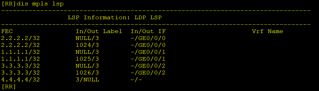
检查MPLS LDP配置
dis mpls lsp
4、MPLS VPN广域网内建立IBGP邻居
使用环回口建立IBGP邻居
# PE1
bgp 100
 undo default ipv4-unicast
 peer 3.3.3.3 as-number 100
 peer 3.3.3.3 connect-interface LoopBack0
 peer 4.4.4.4 as-number 100
 peer 4.4.4.4 connect-interface LoopBack0
 #
 ipv4-family vpnv4
  peer 3.3.3.3 enable
  peer 4.4.4.4 enable

# PE2
bgp 100
 undo default ipv4-unicast
 peer 1.1.1.1 as-number 100
 peer 1.1.1.1 connect-interface LoopBack0
 peer 4.4.4.4 as-number 100
 peer 4.4.4.4 connect-interface LoopBack0
 #
 ipv4-family vpnv4
  peer 1.1.1.1 enable
  peer 4.4.4.4 enable

# RR
bgp 100
 undo default ipv4-unicast
 group ibgp internal
 peer ibgp connect-interface LoopBack0
 peer 1.1.1.1 group ibgp
 peer 3.3.3.3 group ibgp
 #
 ipv4-family vpnv4
  peer ibgp enable
  peer 1.1.1.1 group ibgp
  peer 3.3.3.3 group ibgp
  # 关闭RT值检查
  undo policy vpn-target
注意:路由反射器需要关闭RT值检查,否则它收到PE传过来的路由携带的RT值,发现自己没有与之对应的入方向RT值,就会将路由丢弃,导致路由无法传递。
验证BGP配置
dis bgp vpnv4 all peer

5、PE1和PE2上创建VPN实例
PE1
# 创建VPN实例A
ip vpn-instance A
 ipv4-family
  route-distinguisher 200:1
  vpn-target 1:1 export-extcommunity
  vpn-target 2:2 import-extcommunity

# 创建VPN实例B
ip vpn-instance B
 ipv4-family
  route-distinguisher 200:2
  vpn-target 1:1 export-extcommunity
  vpn-target 2:2 import-extcommunity

# 绑定接口
interface GigabitEthernet0/0/0
 ip binding vpn-instance A
 ip address 66.1.1.1 255.255.255.0
interface GigabitEthernet0/0/1
 ip binding vpn-instance B
 ip address 67.1.1.1 255.255.255.0
PE2
# 创建VPN实例C
ip vpn-instance C
 ipv4-family
  route-distinguisher 300:1
  vpn-target 2:2 export-extcommunity
  vpn-target 1:1 import-extcommunity

# 绑定接口
interface GigabitEthernet0/0/1
 ip binding vpn-instance C
 ip address 69.1.1.1 255.255.255.0
6、PE和CE之间建立EBGP邻居
PE1与CE1、CE2
# PE1
bgp 100
 ipv4-family vpn-instance A
  peer 66.1.1.2 as-number 200
  q
 ipv4-family vpn-instance B
  peer 67.1.1.2 as-number 200

# CE1
bgp 200
 peer 66.1.1.1 as-number 100

# CE2
bgp 200
 peer 67.1.1.1 as-number 100
PE2与CE3
# PE2
bgp 100
 ipv4-family vpn-instance C
  peer 69.1.1.2 as-number 300

# CE3
bgp 300
 peer 69.1.1.1 as-number 100
验证BGP配置
dis bgp peer
dis bgp vpnv4 all peer


7、CE上做路由引入
CE1与CE2(配置命令相同)
# 定义IP前缀列表匹配分公司的路由
ip ip-prefix 5060 permit 10.0.50.0 24
ip ip-prefix 5060 permit 10.0.60.0 24
# 使用路由策略,将分公司的路由过滤
route-policy o2b deny node 10
if-match ip-prefix 5060
q
route-policy o2b permit node 20
q
# 将ospf路由引入bgp,并应用路由策略
bgp 200
 import-route ospf 1 route-policy o2b
# 将BGP路由引入OSPF
ospf
import-route bgp
CE3
# 定义IP前缀列表匹配总公司的路由
ip ip-prefix 1234 permit 10.0.10.0 24
ip ip-prefix 1234 permit 10.0.20.0 24
ip ip-prefix 1234 permit 10.0.30.0 24
ip ip-prefix 1234 permit 10.0.40.0 24
# 使用路由策略,将总公司的路由过滤
route-policy o2b deny node 10
if-match ip-prefix 1234
q
route-policy o2b permit node 20
q
# 将ospf路由引入bgp,并应用路由策略
bgp 300
import-route ospf 1 route-policy o2b
# 将BGP路由引入OSPF
ospf
import-route bgp
查看路由是否引入成功
dis bgp vpnv4 all routing-table

PE1上学习到了从PE2传递过来的分公司的路由,说明路由映入成功并成功传递。
8、修改路由优先级
在CE1上查看IP路由表,发现分公司网段的路由是通过GRE隧道建立的OSPF邻居学到的,并且被优选了。
为了使流量主走mpls,备走gre,需要修改bgp的优先级,使其优于ospf。

查看路由详细信息,可以知道OSPF的路由优先级更高。
dsi ip routing-table 10.0.50.0 verbose

在CE设备上修改EBGP的路由优先级
# CE1、2命令相同
bgp 200
preference 7 255 255
# CE3
bgp 300
preference 7 255 255
9、NAT、防火墙安全策略配置
NAT
# CE1、2、3(配置都一样)
acl number 2000
 rule permit source any
 q
interface GigabitEthernet0/0/0
 nat outbound 2000
防火墙FW1
# 创建地址集
ip address-set 1234 type group
 address 0 10.0.10.0 mask 24
 address 1 10.0.20.0 mask 24
 address 2 10.0.30.0 mask 24
 address 3 10.0.40.0 mask 24
 q
ip address-set 56 type group
 address 0 10.0.50.0 mask 24
 address 1 10.0.60.0 mask 24
 q


security-policy
 # 公司总部与分公司互访
 rule name P_T2U_1234_56
  source-zone trust
  destination-zone untrust
  source-address address-set 1234
  destination-address address-set 56
  action permit
  q
 rule name P_U2T_56_1234
  source-zone untrust
  destination-zone trust
  source-address address-set 56
  destination-address address-set 1234
  action permit
  q
 # 公司总部内访问互联网
 rule name P_T2U_1234_Internet
  source-zone trust
  destination-zone untrust
  source-address address-set 1234
  action permit
10、验证
验证总公司与分公司内网互访

验证总公司与Internet互访

还有一些小瑕疵,比如:
- 做ospf引入bgp的路由策略的时候,没有将FW1与CE、SW7与CE之间的网段也给匹配到。(有可能也本来就不需要做)
- CE1上到达10.0.37.0网段的路由,仍然是通过gre隧道的ospf学习到的,暂时没有排查到原因。

 浙公网安备 33010602011771号