
配置华为交换机动态路由接入M-LAG示例
适用产品和版本
CE16800、CE6881、CE6820、CE6863、CE6863E、CE5881、CE6881K、CE6881E、CE6863K系列交换机V200R020C00或更高版本。
CE12800、CE8850EI、CE8861EI、CE8868EI、CE6856HI、CE6857EI、CE6857E、CE6857F、CE6857F、CE6865EI、CE6865E、CE8850E-32CQ-EI、CE6870EI系列交换机V200R021C00或更高版本。
如果需要了解软件版本与交换机具体型号的配套信息,请查看硬件查询工具。
组网需求
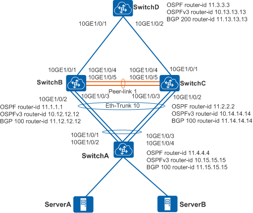
如图1-22所示,SwitchB和SwitchC组成M-LAG系统,SwitchB和SwitchC的M-LAG端口支持动态路由协议,用户在SwitchA上配置动态路由通过三层路由方式接入到M-LAG系统。
|
设备名称 |
接口编号 |
VLAN及IP地址 |
对接设备及接口编号 |
|---|---|---|---|
|
SwitchA
|
Eth-Trunk 10
|
VLAN 100:IPv4地址 10.100.0.2/24 VLAN 101:IPv6地址 2001:DB8:101::2/64 VLAN 102:IPv4地址 10.102.0.2/24 VLAN 103:IPv6地址 2001:DB8:103::2/64 |
SwitchB:Eth-Trunk 10
|
|
SwitchC:Eth-Trunk 10
|
|||
|
SwitchB
|
管理网口 |
10.200.1.1/24 |
- |
|
10GE1/0/1 |
IP地址:192.168.1.1/24 IPv6地址:2001:DB8:1::1/64 |
SwitchD:10GE1/0/1 |
|
|
Eth-Trunk 1
|
- |
SwitchC:Eth-Trunk 1
|
|
|
Eth-Trunk 10
|
VLAN 100:IPv4地址 10.100.0.1/24 M-LAG IPv4地址 10.100.0.3/24 VLAN 101:IPv6地址 2001:DB8:101::1/64 M-LAG Link-local地址 FE80:1000::1 VLAN 102:IPv4地址 10.102.0.1/24 M-LAG IPv4地址 10.102.0.3/24 VLAN 103:IPv6地址 2001:DB8:103::1/64 M-LAG IPv6地址 2001:DB8:103::3/64 |
SwitchA:Eth-Trunk 10
|
|
|
LoopBack 1 |
10.2.2.2/32 |
- |
|
|
LoopBack 2 |
10.3.3.3/32 |
- |
|
|
SwitchC
|
管理网口 |
10.200.2.1/24 |
- |
|
10GE1/0/1 |
192.168.2.1/24 2001:DB8:2::1/64 |
SwitchD:10GE1/0/2 |
|
|
Eth-Trunk 1
|
- |
SwitchB:Eth-Trunk 1
|
|
|
Eth-Trunk 10
|
VLAN 100: IPv4地址 10.100.0.1/24 M-LAG IPv4地址 10.100.0.4/24 VLAN 101: IPv6地址 2001:DB8:101::1/64 M-LAG Link-local地址 FE80:1000::2 VLAN 102: IPv4地址 10.102.0.1/24 M-LAG IPv4地址 10.102.0.4/24 VLAN 103: IPv6地址 2001:DB8:103::1/64 M-LAG IPv6地址 2001:DB8:103::4/64 |
SwitchA:Eth-Trunk 10
|
|
|
LoopBack 1 |
10.2.2.2/32 |
- |
|
|
LoopBack 2 |
10.4.4.4/32 |
- |
|
|
SwitchD |
10GE1/0/1 |
192.168.1.2/24 2001:DB8:1::2/64 |
SwitchB:10GE1/0/1 |
|
10GE1/0/2 |
192.168.2.2/24 2001:DB8:2::2/64 |
SwitchC:10GE1/0/1 |
|
|
LoopBack 1 |
10.1.1.1/32 |
- |
配置思路
采用如下的思路配置:
- 配置SwitchA、SwitchB、SwitchC建立M-LAG系统。
- 配置SwitchB和SwitchC的V-STP。
- 配置SwitchB和SwitchC的DFS Group并绑定管理网口的IP地址。
- 配置SwitchB和SwitchC之间的peer-link链路。
- 配置SwitchB和SwitchC的M-LAG成员接口,SwitchA的Eth-Trunk接口。
- 配置SwitchB和SwitchC的Monitor Link功能。
Monitor Link将上行接口和下行接口关联,避免因上行链路故障导致用户侧流量无法转发而丢弃。
- 配置OSPF接入M-LAG。
- 配置SwitchB、SwitchC、SwitchD的路由协议OSPF,实现网络三层互通。
- 配置SwitchB和SwitchC的动态路由OSPF接入M-LAG的IPv4地址。
SwitchB和SwitchC上需要配置不一样的M-LAG IPv4地址,否则会导致路由协议邻居建立不起来。
- 配置SwitchA和M-LAG成员设备建立动态路由OSPF的IP地址。
- 配置OSPFv3接入M-LAG。
- 配置SwitchB、SwitchC、SwitchD的路由协议OSPFv3,实现网络三层互通。
- 配置SwitchB和SwitchC的动态路由OSPFv3接入M-LAG的Link-local地址。
SwitchB和SwitchC上需要配置不一样的M-LAG Link-local地址,否则会导致路由协议邻居建立不起来。
- 配置SwitchA和M-LAG成员设备建立动态路由OSPFv3的IPv6地址。
- 配置BGP接入M-LAG。
- 配置SwitchB、SwitchC、SwitchD的路由协议BGP,实现网络三层互通。
- 配置SwitchB和SwitchC的动态路由BGP接入M-LAG的IPv4地址。
SwitchB和SwitchC上需要配置不一样的M-LAG IPv4地址,否则会导致路由协议邻居建立不起来。
- 配置SwitchA和M-LAG成员设备(SwitchB、SwitchC)建立动态路由BGP的对等体。
- 配置BGP4+接入M-LAG。
- 配置SwitchB、SwitchC、SwitchD的路由协议BGP4+,实现网络三层互通。
- 配置SwitchB和SwitchC的动态路由BGP接入M-LAG的IPv6地址。
SwitchB和SwitchC上需要配置不一样的M-LAG IPv6地址,否则会导致路由协议邻居建立不起来。
- 配置SwitchA和M-LAG成员设备(SwitchB、SwitchC)建立动态路由BGP4+的对等体和引入路由。

操作步骤
- 配置SwitchA、SwitchB、SwitchC建立M-LAG系统。
- 配置OSPF接入M-LAG。
- 配置OSPFv3接入M-LAG。
- 配置BGP接入M-LAG。
- 配置BGP4+接入M-LAG。
- 验证配置结果
-
执行命令display dfs-group 1 m-lag,查看M-LAG的相关信息。
# 查看DFS Group编号为1的M-LAG信息。
[~SwitchB] display dfs-group 1 m-lag
*                : Local node
Heart beat state : OK
Node 1 *
  Dfs-Group ID   : 1
  Priority       : 100
  Address        : ip address 10.200.1.1
  State          : Master
  Causation      : -
  System ID      : 0025-9e95-7c11
  SysName        : SwitchB
  Version        :V200R020C00
  Device Type    :CE16800
Node 2
  Dfs-Group ID   : 1
  Priority       : 100
  Address        : ip address 10.200.2.1
  State          : Backup
  Causation      : -
  System ID      : 0025-9e95-7c31
  SysName        : SwitchC
  Version        :V200R020C00
  Device Type    :CE16800
# 查看SwitchB上的M-LAG信息。
[~SwitchB] display dfs-group 1 node 1 m-lag brief
* - Local node

M-Lag ID     Interface      Port State    Status                Consistency-check
       1     Eth-Trunk 10   Up            active(*)-active      --

Failed reason:
    1 -- Relationship between vlan and port is inconsistent
    2 -- STP configuration under the port is inconsistent
    3 -- STP port priority configuration is inconsistent
    4 -- LACP mode of M-LAG is inconsistent
    5 -- M-LAG configuration is inconsistent
    6 -- The number of M-LAG members is inconsistent
# 查看SwitchC上的M-LAG信息。
[~SwitchC] display dfs-group 1 node 2 m-lag brief * - Local node M-Lag ID Interface Port State Status Consistency-check 1 Eth-Trunk 10 Up active(*)-active -- Failed reason: 1 -- Relationship between vlan and port is inconsistent 2 -- STP configuration under the port is inconsistent 3 -- STP port priority configuration is inconsistent 4 -- LACP mode of M-LAG is inconsistent 5 -- M-LAG configuration is inconsistent 6 -- The number of M-LAG members is inconsistent -
在SwitchB、SwitchC、SwitchA上执行display ospf peer brief命令,可查看到OSPF中各邻居的信息。
# 查看SwitchB上的OSPF邻居信息。
[~SwitchB] display ospf peer brief
        OSPF Process 1 with Router ID 11.1.1.1
                  Peer Statistic Information
  Total number of peer(s): 3
  Peer(s) in full state: 3
  ----------------------------------------------------------------------------
  Area Id         Interface                  Neighbor id      State
  0.0.0.0         10GE1/0/1                  11.3.3.3         Full
  0.0.0.0         Vlanif100                  11.2.2.2         Full
  0.0.0.0         Vlanif100                  11.4.4.4         Full
# 查看SwitchC上的OSPF邻居信息。
[~SwitchC] display ospf peer brief
        OSPF Process 1 with Router ID 11.2.2.2
                  Peer Statistic Information
  Total number of peer(s): 3
  Peer(s) in full state: 3
  ----------------------------------------------------------------------------
  Area Id         Interface                  Neighbor id      State
  0.0.0.0         10GE1/0/1                  11.3.3.3         Full
  0.0.0.0         Vlanif100                  11.1.1.1         Full
  0.0.0.0         Vlanif100                  11.4.4.4         Full
# 查看SwitchA上的OSPF邻居信息。
[~SwitchA] display ospf peer brief OSPF Process 1 with Router ID 11.4.4.4 Peer Statistic Information Total number of peer(s): 2 Peer(s) in full state: 2 ---------------------------------------------------------------------------- Area Id Interface Neighbor id State 0.0.0.0 Vlanif100 11.1.1.1 Full 0.0.0.0 Vlanif100 11.2.2.2 Full -
在SwitchB、SwitchC、SwitchA上执行display ospfv3 peer命令,可查看到OSPFv3中各邻居的信息。
# 查看SwitchB上的OSPFv3邻居信息。[~SwitchB] display ospfv3 peer OSPFv3 Process (1) Total number of peer(s): 3 Peer(s) in full state: 3 OSPFv3 Area (0.0.0.0) Neighbor ID Pri State Dead Time Interface Instance ID 10.13.13.13 1 Full/Backup 00:00:37 10GE1/0/1 0 10.14.14.14 1 Full/DROther 00:00:38 Vlanif101 0 10.15.15.15 1 Full/DR 00:00:40 Vlanif101 0# 查看SwitchC上的OSPFv3邻居信息。
[~SwitchC] display ospfv3 peer
OSPFv3 Process (1)
Total number of peer(s): 3
 Peer(s) in full state: 3
OSPFv3 Area (0.0.0.0)
Neighbor ID      Pri State            Dead Time  Interface          Instance ID
10.13.13.13        1 Full/DR          00:00:37   10GE1/0/1             0
10.12.12.12        1 Full/DROther     00:00:38   Vlanif101             0
10.15.15.15        1 Full/DR          00:00:40   Vlanif101             0
# 查看SwitchA上的OSPFv3邻居信息。
[~SwitchA]display ospfv3 peer OSPFv3 Process (1) Total number of peer(s): 2 Peer(s) in full state: 2 OSPFv3 Area (0.0.0.0) Neighbor ID Pri State Dead Time Interface Instance ID 10.14.14.14 1 Full/DROther 00:00:38 Vlanif101 0 10.12.12.12 1 Full/Backup 00:00:40 Vlanif101 0 -
在SwitchB、SwitchC、SwitchA上执行display bgp peer命令,可查看到BGP中各邻居的信息。
# 查看SwitchB上的BGP邻居信息。
[~SwitchB] display bgp peer
 Status codes: * - Dynamic
 BGP local router ID        : 11.12.12.12
 Local AS number            : 100
 Total number of peers      : 2
 Peers in established state : 2
 Total number of dynamic peers : 0

  Peer                             V          AS  MsgRcvd  MsgSent  OutQ  Up/Down       State  PrefRcv
  10.102.0.2                       4         100       30       30     0 00:24:37 Established        0
  192.168.1.2                      4         200       64       66     0 00:54:13 Established        0
# 查看SwitchC上的BGP邻居信息。
[~SwitchC] display bgp peer
 Status codes: * - Dynamic
 BGP local router ID        : 11.14.14.14
 Local AS number            : 100
 Total number of peers      : 59
 Peers in established state : 2
 Total number of dynamic peers : 0

  Peer                             V          AS  MsgRcvd  MsgSent  OutQ  Up/Down       State  PrefRcv
  10.102.0.2                       4         100       34       33     0 00:26:56 Established        0
  192.168.2.2                      4         200       71       72     0 00:59:44 Established        0
# 查看SwitchA上的BGP邻居信息。
[~SwitchA] display bgp peer 2020-07-07 21:06:02.443 Status codes: * - Dynamic BGP local router ID : 11.15.15.15 Local AS number : 100 Total number of peers : 2 Peers in established state : 2 Total number of dynamic peers : 0 Peer V AS MsgRcvd MsgSent OutQ Up/Down State PrefRcv 10.102.0.3 4 100 29 29 0 00:23:22 Established 0 10.102.0.4 4 100 29 30 0 00:23:18 Established 0 -
在SwitchB、SwitchC、SwitchA上执行display bgp ipv6 peer命令,可查看到BGP4+中各邻居的信息。
# 查看SwitchB上的BGP4+邻居信息。
[~SwitchB] display bgp ipv6 peer
 Status codes: * - Dynamic
 BGP local router ID        : 11.12.12.12
 Local AS number            : 100
 Total number of peers      : 2
 Peers in established state : 2
 Total number of dynamic peers : 0

  Peer                             V          AS  MsgRcvd  MsgSent  OutQ  Up/Down       State  PrefRcv
  2001:DB8:1::2                    4         200       61       61     0 00:50:07 Established        2
  2001:DB8:103::2                  4         100        5        6     0 00:02:18 Established        0
# 查看SwitchC上的BGP4+邻居信息。
[~SwitchC] display bgp ipv6 peer
 Status codes: * - Dynamic
 BGP local router ID        : 11.14.14.14
 Local AS number            : 100
 Total number of peers      : 2
 Peers in established state : 2
 Total number of dynamic peers : 0

  Peer                             V          AS  MsgRcvd  MsgSent  OutQ  Up/Down       State  PrefRcv
  2001:DB8:2::2                    4         200       76       75     0 01:03:13 Established        2
  2001:DB8:103::2                  4         100       21       22     0 00:15:55 Established        0
# 查看SwitchA上的BGP4+邻居信息。
[~SwitchA] display bgp ipv6 peer
 Status codes: * - Dynamic
 BGP local router ID        : 11.15.15.15
 Local AS number            : 100
 Total number of peers      : 2
 Peers in established state : 2
 Total number of dynamic peers : 0

  Peer                             V          AS  MsgRcvd  MsgSent  OutQ  Up/Down       State  PrefRcv
  2001:DB8:103::3                  4         100        7        7     0 00:03:02 Established        1
  2001:DB8:103::4                  4         100        7        6     0 00:02:33 Established        1
-
配置文件
-
SwitchA的配置文件
#
sysname SwitchA
#
vlan batch 100 to 103
#
ospfv3 1
 router-id 10.15.15.15
 area 0.0.0.0
#
interface Vlanif100
 ip address 10.100.0.2 255.255.255.0
#
interface Vlanif101
 ipv6 enable
 ipv6 address 2001:DB8:101::2/64
 ospfv3 1 area 0.0.0.0
#
interface Vlanif102
 ip address 10.102.0.2 255.255.255.0
#
interface Vlanif103
 ipv6 enable
 ipv6 address 2001:DB8:103::2/64
#
interface Eth-Trunk10
 port link-type trunk
 undo port trunk allow-pass vlan 1
 port trunk allow-pass vlan 100 101 102 103
 mode lacp-static
 lacp mixed-rate link enable
#
interface 10GE1/0/1
 eth-trunk 10
#
interface 10GE1/0/2
 eth-trunk 10
#
interface 10GE1/0/3
 eth-trunk 10
#
interface 10GE1/0/4
 eth-trunk 10
#
bgp 100
 router-id 11.15.15.15
 peer 10.102.0.3 as-number 100
 peer 10.102.0.4 as-number 100
 peer 2001:DB8:103::3 as-number 100
 peer 2001:DB8:103::4 as-number 100
 #
 ipv4-family unicast
  peer 10.102.0.3 enable
  peer 10.102.0.4 enable
 #
 ipv6-family unicast
  peer 2001:DB8:103::3 enable
  peer 2001:DB8:103::4 enable
#
ospf 1 router-id 11.4.4.4
 area 0.0.0.0
  network 10.100.0.0 0.0.0.255
#
return
-
SwitchB的配置文件
#
sysname Leaf
#
dfs-group 1
 source ip 10.200.1.1
#
vlan batch 100 to 103
#
stp mode rstp
stp v-stp enable
#
ospfv3 1
 router-id 10.12.12.12
 area 0.0.0.0
#
interface Vlanif100
 ip address 10.100.0.1 255.255.255.0
 ospf source sub-address 10.100.0.3
 mac-address 0000-5e00-0101
 m-lag ip address 10.100.0.3 255.255.255.0
#
interface Vlanif101
 ipv6 enable
 ipv6 address 2001:DB8:101::1/64
 ospfv3 1 area 0.0.0.0
 mac-address 0000-5e00-0102
 m-lag ipv6 address FE80:1000::1 link-local
#
interface Vlanif102
 ip address 10.102.0.1 255.255.255.0
 mac-address 0000-5e00-0103
 m-lag ip address 10.102.0.3 255.255.255.0
#
interface Vlanif103
 ipv6 enable
 ipv6 address 2001:DB8:103::1/64
 mac-address 0000-5e00-0104
 m-lag ipv6 address 2001:DB8:103::3
#
interface Eth-Trunk1
 mode lacp-static
 peer-link 1
#
interface Eth-Trunk10
 port link-type trunk
 undo port trunk allow-pass vlan 1
 port trunk allow-pass vlan 100 101 102 103
 mode lacp-static
 lacp mixed-rate link enable
 dfs-group 1 m-lag 1
#
interface 10GE1/0/1
 undo portswitch
 ipv6 enable
 ip address 192.168.1.1 255.255.255.0
 ipv6 address 2001:DB8:1::1/64
 ospfv3 1 area 0.0.0.0
#
interface 10GE1/0/2
 eth-trunk 10
#
interface 10GE1/0/3
 eth-trunk 10
#
interface 10GE1/0/4
 eth-trunk 1
#
interface 10GE1/0/5
 eth-trunk 1
#
interface LoopBack1
 ip address 10.2.2.2 255.255.255.255
#
interface LoopBack2
 ip address 10.3.3.3 255.255.255.255
#
monitor-link group 1
 port 10ge 1/0/1 uplink
 port eth-trunk 10 downlink 1
#
bgp 100
 router-id 11.12.12.12
 peer 10.102.0.2 as-number 100
 peer 10.102.0.2 connect-interface Vlanif102 10.102.0.3
 peer 192.168.1.2 as-number 200
 peer 2001:DB8:1::2 as-number 200
 peer 2001:DB8:103::2 as-number 100
 peer 2001:DB8:103::2 connect-interface Vlanif103 2001:DB8:103::3
 #
 ipv4-family unicast
  peer 10.102.0.2 enable
  peer 192.168.1.2 enable
#
 ipv6-family unicast
  network 2001:DB8:1:: 64
  peer 2001:DB8:1::2 enable
  peer 2001:DB8:103::2 enable
#
ospf 1 router-id 11.1.1.1
 area 0.0.0.0
  network 10.2.2.2 0.0.0.0
  network 10.3.3.3 0.0.0.0
  network 10.100.0.0 0.0.0.255
  network 192.168.1.0 0.0.0.255
#
return
-
SwitchC的配置文件
#
sysname SwitchC
#
dfs-group 1
 source ip 10.200.2.1
#
vlan batch 100 to 103
#
stp mode rstp
stp v-stp enable
#
ospfv3 1
 router-id 10.14.14.14
 area 0.0.0.0
#
interface Vlanif100
 ip address 10.100.0.1 255.255.255.0
 ospf source sub-address 10.100.0.4
 mac-address 0000-5e00-0101
 m-lag ip address 10.100.0.4 255.255.255.0
#
interface Vlanif101
 ipv6 enable
 ipv6 address 2001:db8:101::1/64
 ospfv3 1 area 0.0.0.0
 mac-address 0000-5e00-0102
 m-lag ipv6 address FE80:1000::2 link-local
#
interface Vlanif102
 ip address 10.102.0.1 255.255.255.0
 mac-address 0000-5e00-0103
 m-lag ip address 10.102.0.4 255.255.255.0
#
interface Vlanif103
 ipv6 enable
 ipv6 address 2001:DB8:103::1/64
 mac-address 0000-5e00-0104
 m-lag ipv6 address 2001:DB8:103::4
#
interface Eth-Trunk1
 mode lacp-static
 peer-link 1
#
interface Eth-Trunk10
 port link-type trunk
 undo port trunk allow-pass vlan 1
 port trunk allow-pass vlan 100 101 102 103
 mode lacp-static
 lacp mixed-rate link enable
 dfs-group 1 m-lag 1
#
interface 10GE1/0/1
 undo portswitch
 ipv6 enable
 ip address 192.168.2.1 255.255.255.0
 ipv6 address 2001:db8:2::1/64
 ospfv3 1 area 0.0.0.0
#
interface 10GE1/0/2
 eth-trunk 10
#
interface 10GE1/0/3
 eth-trunk 10
#
interface 10GE1/0/4
 eth-trunk 1
#
interface 10GE1/0/5
 eth-trunk 1
#
interface LoopBack1
 ip address 10.2.2.2 255.255.255.255
#
interface LoopBack2
 ip address 10.4.4.4 255.255.255.255
#
monitor-link group 1
 port 10ge 1/0/1 uplink
 port eth-trunk 10 downlink 1
#
bgp 100
 router-id 11.14.14.14
 peer 10.102.0.2 as-number 100
 peer 10.102.0.2 connect-interface Vlanif102 10.102.0.4
 peer 192.168.2.2 as-number 200
 peer 2001:DB8:2::2 as-number 200
 peer 2001:DB8:103::2 as-number 100
 peer 2001:DB8:103::2 connect-interface Vlanif103 2001:DB8:103::4
 #
 ipv4-family unicast
  peer 10.102.0.2 enable
  peer 192.168.2.2 enable
 #
 ipv6-family unicast
  network 2001:DB8:2:: 64
  peer 2001:DB8:2::2 enable
  peer 2001:DB8:103::2 enable
#
ospf 1 router-id 11.2.2.2
 area 0.0.0.0
  network 10.2.2.2 0.0.0.0
  network 10.4.4.4 0.0.0.0
  network 10.100.0.0 0.0.0.255
  network 192.168.2.0 0.0.0.255
#
return
-
SwitchD的配置文件
#
sysname SwitchD
#
ospfv3 1
 router-id 10.13.13.13
 area 0.0.0.0
#
interface 10GE1/0/1
 undo portswitch
 ipv6 enable
 ip address 192.168.1.2 255.255.255.0
 ipv6 address 2001:db8:1::2/64
 ospfv3 1 area 0.0.0.0
#
interface 10GE1/0/2
 undo portswitch
 ipv6 enable
 ip address 192.168.2.2 255.255.255.0
 ipv6 address 2001:db8:2::2/64
 ospfv3 1 area 0.0.0.0
#
interface LoopBack1
 ip address 10.1.1.1 255.255.255.255
#
bgp 200
 router-id 11.13.13.13
 peer 192.168.1.1 as-number 100
 peer 192.168.2.1 as-number 100
 peer 2001:db8:1::1 as-number 100
 peer 2001:db8:2::1 as-number 100
 #
 ipv4-family unicast
  peer 192.168.1.1 enable
  peer 192.168.2.1 enable
 #
 ipv6-family unicast
  network 2001:db8:1:: 64
  network 2001:db8:2:: 64
  peer 2001:db8:1::1 enable
  peer 2001:db8:2::1 enable
#
ospf 1 router-id 11.3.3.3
 area 0.0.0.0
  network 10.1.1.1 0.0.0.0
  network 192.168.1.0 0.0.0.255
  network 192.168.2.0 0.0.0.255
#
return
-

 浙公网安备 33010602011771号