软光栅从零开始——shader和法线贴图
前言
https://github.com/ssloy/tinyrenderer/wiki/Lesson-6:-Shaders-for-the-software-renderer本系列基于此教程总结
在上一篇中,我们学会了如何将物体从局部空间变化到世界空间中;如何移动摄像机;如何进行透视投影,接下来我们将涉及shader部分,基于现代渲染管线来设计shader,并学习如何实现法线贴图、切线空间
shader分类
shader的种类有不少,但我们只涉及以下两类
- 顶点着色器:用于转换输入的顶点坐标
- 片元着色器:确定当前像素的颜色。片元着色器接收顶点着色器的输出顶点
因此,我们需要之前的有关代码移至shader中
实现
在这里我们设计一个抽象类——包含顶点着色器和片元着色器的功能,并根据它来衍生出其他种类的shader类
struct IShader
{
    virtual ~IShader();
    virtual Vec4f Vertex(int iFace, int nthVert) = 0;
    virtual bool fragment(const Vec3f bar, TGAColor& color) = 0;
};
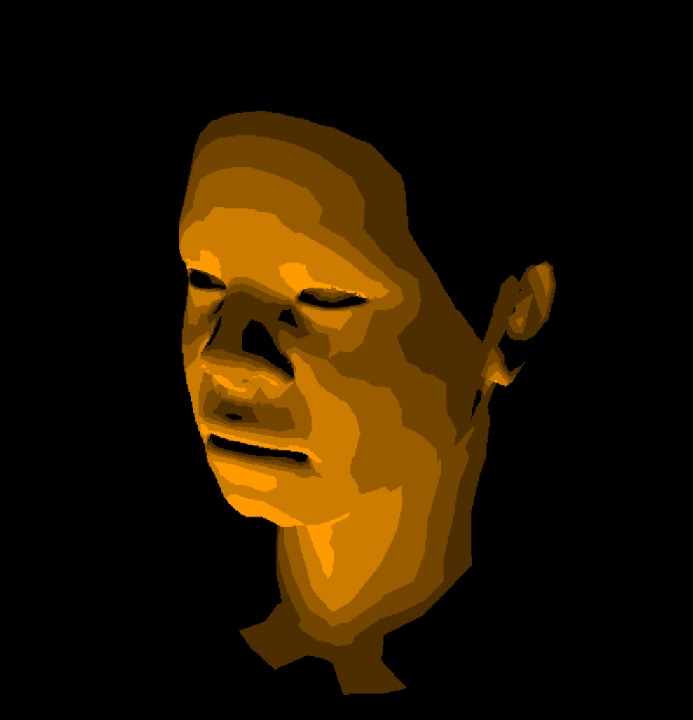
比如接下来实现的ground(逐顶点)着色
struct GouraudShader : public IShader
{
    Vec3f m_varyingIntensity; // written by vertex shader, read by fragment shader

    //处理导入模型的顶点
    virtual Vec4f Vertex(int iFace, int nthVert)
    {
        m_varyingIntensity[nthVert] = std::max(0.f, g_model->normal(iFace, nthVert) * g_LightDir); // 求光照
        Vec4f m_vertex = embed<4>(g_model->vert(iFace, nthVert)); // 从.obj文件中读取顶点数据
        return g_Viewport * g_Projection * g_ModelView * m_vertex; // 转换到viewport
    }

    //确定当前像素颜色
    virtual bool fragment(Vec3f bar, TGAColor& color)
    {
        auto intensity = m_varyingIntensity * bar;   // 三角形重心插值
        if (intensity > .85) intensity = 1;
        else if (intensity > .60) intensity = .80;
        else if (intensity > .45) intensity = .60;
        else if (intensity > .30) intensity = .45;
        else if (intensity > .15) intensity = .30;
        else intensity = 0;
        color = TGAColor(255, 155, 0) * intensity;
        //片元着色器可以丢弃该像素,如此在光栅化阶段会跳过该像素
        return false;                              // whether discard the pixel.true : yes, false : no;
    }
};
输出如下:
纹理
对于纹理也是由片元着色器完成,因此我们将其归入着色器抽象类,由顶点着色器读取uv数据,片元着色器来决定是否使用该uv
struct Shader : public IShader
{
    //...
    mat < 2, 3, float > m_varyingUV;
};
static mat<DimRows,DimCols,T> identity()
{
    mat<DimRows,DimCols,T> ret;
    for (size_t i=DimRows; i--; )
        for (size_t j=DimCols;j--; ret[i][j]=(i==j));
    return ret;
}

virtual Vec4f Vertex(int iFace, int nthVert)
{
    m_varyingUV.set_col(nthVert, g_model->uv(iFace, nthVert));
    //...
}
void set_col(size_t idx, vec<DimRows,T> v)
{
    assert(idx<DimCols);
    for (size_t i = DimRows; i--; rows[i][idx]=v[i]);
}

virtual bool fragment(Vec3f bar, TGAColor& color)
{
    //...
    Vec2f uv = m_varyingUV * bar;	//uv坐标插值
    color = g_model->diffuse(uv) * intensity;	//对当前像素点设置颜色
    return false;
}
输出结果:
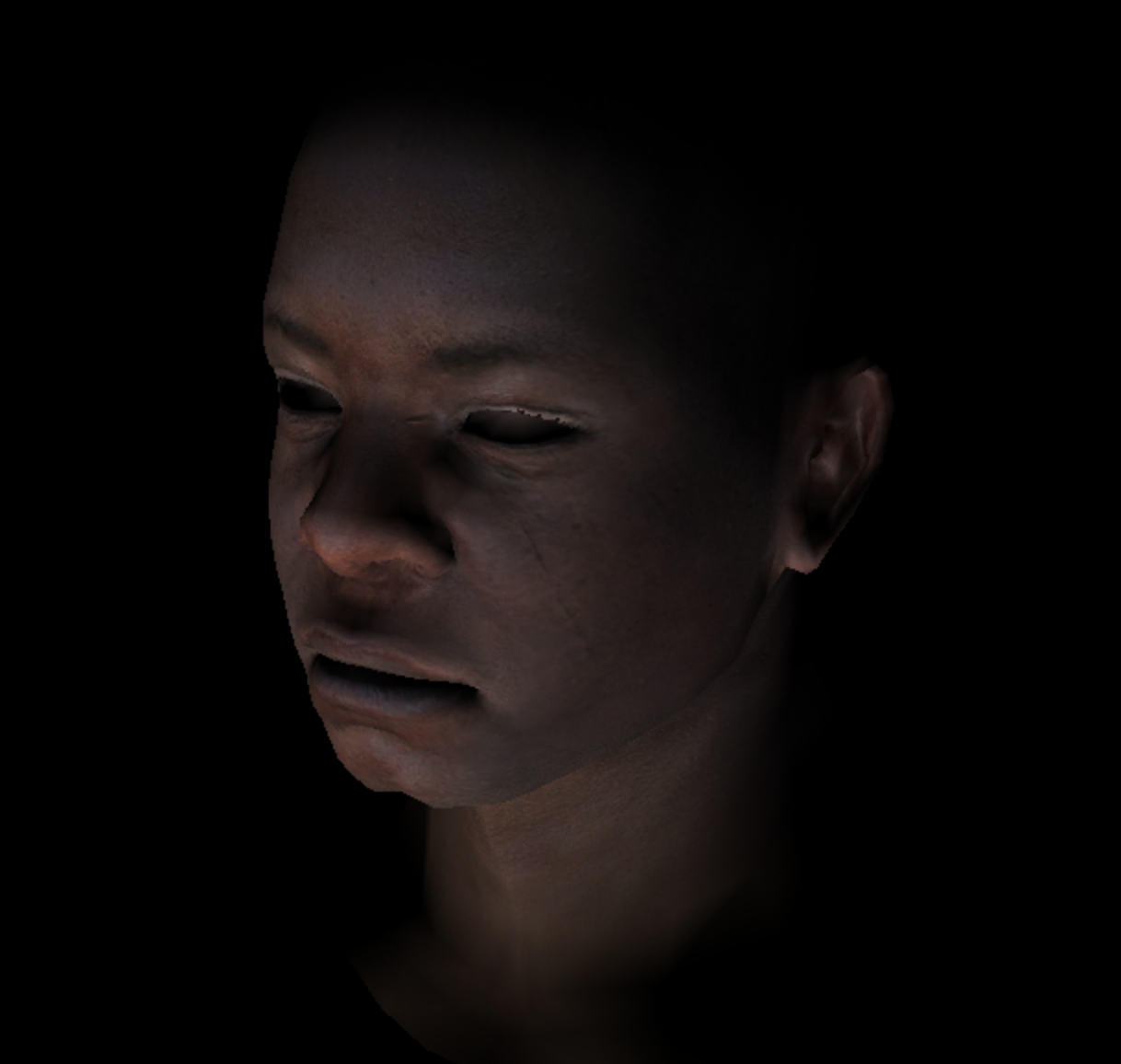
法线贴图
什么是切线空间?
切线空间是一个单独的坐标系,它的坐标原点为一个顶点,z轴为该点的法线方向,而xy轴是和该点相切的两条切线。问题来了,z轴为法线方向这很好求,但是一个球面的某点的一个切平面却有许许多多的切线,我们如何确定它的xy轴呢?一般来说,建模软件选择以UV方向作为切线方向xy轴

需要注意的是,rgb值范围为[0,1],而切线空间中法线的范围为[-1,1],因此我们需要对其进行映射
为什么需要切线空间?
值得深思的是在模型的每个顶点处都会提供该点的法线,那我们为什么还需要切线空间呢?
比如进行Blinn-Phong光照时,我们想要物体有更加明显的凹凸感(本质是顶点的高度位移),需要更多的顶点,随之带来的问题是计算量很大,影响性能。而利用切线空间便不再需要大量的顶点数据,我们将某个顶点的法向量存储在切线空间中,该法向量的高度位移会随着xy值的变化而变化,我们将这些偏移量存储在贴图中,这个贴图被称为法线贴图
模型空间和切线空间存储法向量的不同
-
object space
优点
- 直观
缺点
- 当顶点发生变动时(骨骼动画),无法计算新的法线(法线随面变化而变化)
- 方向各异,无法压缩
-
tangent space
- 对于tangent space而言,即使顶点发生变化,也能得到合理结果
- 可以重用法线纹理
- 可以压缩.因为tangent space的z方向为正方向,所以可以仅仅存储xy轴的数据,由xy方向求z方向
- 下面两张图,第一张是切线空间,第二张是模型空间,这是可以直接一眼分辨出来的,何以见得?
- 模型空间:法线方向各不相同,因此是五颜六色的
- 切线空间:xyz坐标会规范化为[-1,1],但xyz本质是一种纹理,因此需要将其映射至[0,1]——\(pixel = (normal + 1) / 2\),也就是说该值是大于0.5的,因此整体偏蓝


-
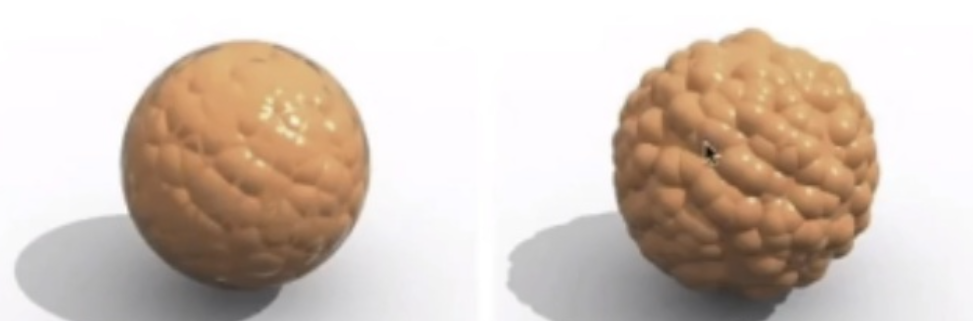
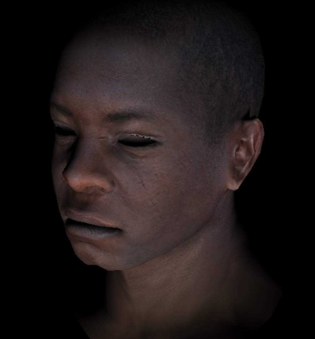
法线贴图实现的假凹凸和真凹凸在物理视觉上是有区别的
如下图中,左侧为法线贴图,它的阴影光滑没有凹凸感,而右图为真凹凸,阴影有凹凸感
TBN矩阵
-
什么是TBN矩阵,为什么需要它?
一般来说计算光照,我们通常在世界空间/模型空间中计算法线方向。由于我们学习了切线空间,因此我们需要一个变换矩阵 ,用于将切线空间中的法向量变换至世界空间/模型空间中
TBN矩阵是一个由切线空间变换到世界空间/模型空间的变换矩阵,其中包含三个向量——T、B、N,分别表示为切线,负切线,法线.由于TBN矩阵关心的是向量而非点,因此用3x3的矩阵表示即可
-
从切线空间变换至世界空间
因为切线空间是一个标准化空间(范围为[0,1]),因此我们只需求得在世界空间中TBN三个向量的坐标,即可求得TBN矩阵
-
从世界空间到切线空间
-
为什么需要从世界空间变化到切线空间?
将光照方向和摄像机方向放在顶点着色器中计算光照,使得不必在片元主送二七中进行更耗时的计算
-
如何求得?
我们已经知道如何从切线空间变化到世界空间,因此只需求TBN矩阵的逆矩阵即可。两种方法
- 利用逆矩阵性质:设\(A = \left[\begin{array}{cc} a & b \\ c & d \end{array} \right] ,则有A^{-1} = \frac{1}{ad - bc} \left[\begin{array}{cc} d & -b \\ -c & a \end{array} \right]\)
- 若TBN矩阵没有涉及平移,则该矩阵为正交矩阵,因此它的转置矩阵就是逆矩阵
-
变换法向量
因为变换到世界空间可能会导致模型的位置形状发生改变,法向量将不再与原xy向量正切,因此在此处需要进行法向量的变换(在这篇我推到过如何变换法向量https://www.cnblogs.com/chenglixue/p/17140982.html)——法向量的变换矩阵为变换矩阵的逆转置矩阵
实现
-
什么是uniform
在HLSL中,uniform是一个关键字,简单来说它是一个全局变量,在任意shader中都可对其进行访问,它和const类似,初始化后无法进行更改
-
uniform的作用
在现代图形API中,使用uniform将常量传递给shader供其使用
struct NormalMappingShader : public IShader
{
    //...
    mat < 2, 3, float > m_varyingUV;//uv纹理
    mat<4, 4, float> m_uniformM;	//变换矩阵
    mat<4, 4, float> m_uniformMIT;	//逆转置变换矩阵

    //...
    virtual bool fragment(Vec3f bar, TGAColor& color)
    {
        Vec2f uv = m_varyingUV * bar;	//插值
        //法线进行空间变化后和原向量不再相切,因此需要乘以空间变化矩阵的逆转置矩阵
        auto n = proj<3>(m_uniformMIT * embed<4>(g_model->normal(uv))).normalize();
        auto l = proj<3>(m_uniformM * embed<4>(g_LightDir)).normalize();	//光源
        auto intensity = std::max(0.f, n * l);
        color = g_model->diffuse(uv) * intensity;
        return false;                              // whether discard the pixel.true : yes, false : no;
    }
}

GouraudShader shader;
shader.m_uniformM = g_Projection * g_ModelView;		//变换矩阵
shader.m_uniformMIT = (g_Projection * g_ModelView).invert_transpose();	//变换矩阵的逆转置矩阵
for (int i = 0; i < g_model->nfaces(); ++i)
{
    Vec4f clipVerts[3];  //clip coordinates.written by VS, read by FS
    for (int j : {0, 1, 2})
    {
        clipVerts[j] = shader.Vertex(i, j);
    }
    rasterization(clipVerts, shader, frameBuffer, ZBuffer);
}
输出:
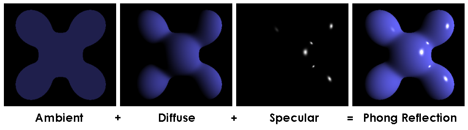
phone光照模型
phone光照模型由漫反射光、镜面反射光、环境光组成。如下图所示:
-
漫反射光系数
漫反射光照系数很好求,就是一个点乘\(std::max(0.f, n * l)\)
-
环境光系数
环境光系数只需给予一个常量值
-
镜面反射光系数
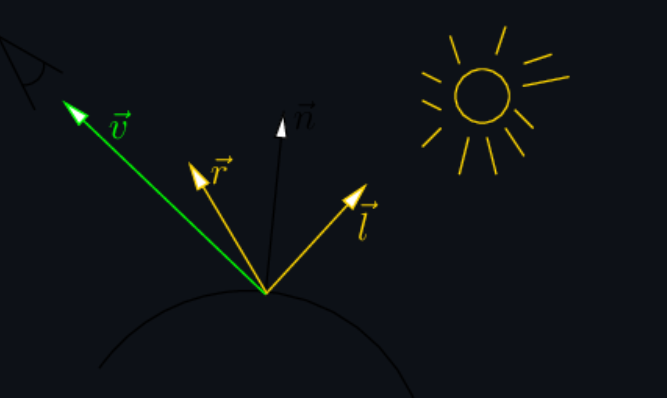
对于镜面反射光我们需要求得反射光r。如下图所示,r为\(2n * dot(n,l) - l\)
在此处,我们将\(dot(v,r)\)进行一些更改,否则该光泽会较大。因为该余弦值描述的是光照范围,所以我们对余弦乘以十次方,即可得到一个光照范围较小的辉光
因为对于镜面光而言只是部分范围会有光泽,所以我们将镜面光幂存储在镜面贴图纹理中
-
不使用切线空间的实现
struct PhoneShader : public IShader
{
    mat < 2, 3, float > m_varyingUV;
    mat<4, 4, float> m_uniformM;
    mat<4, 4, float> m_uniformMIT;

    virtual Vec4f Vertex(int iFace, int nthVert)
    {
        m_varyingUV.set_col(nthVert, g_model->uv(iFace, nthVert));
        Vec4f m_vertex = embed<4>(g_model->vert(iFace, nthVert)); // read the vertex from .obj file
        return g_Viewport * g_Projection * g_ModelView * m_vertex; // transform it to screen coordinates
    }

    virtual bool fragment(Vec3f bar, TGAColor& color)
    {
        Vec2f uv = m_varyingUV * bar;
        auto n = proj<3>(m_uniformMIT * embed<4>(g_model->normal(uv))).normalize();
        auto l = proj<3>(m_uniformM * embed<4>(g_LightDir)).normalize();
        auto r = (n * (n * l) * 2 - l).normalize();	//镜面反射光
        float spec = std::pow(std::max(r.z, 0.f), g_model->specular(uv));	//幂存放在镜面贴图纹理中
        float diff = std::max(0.f, n * l);	//漫反射光
        TGAColor c = g_model->diffuse(uv);
        color = c;
        for (int i = 0; i < 3; ++i)
            color[i] = std::min<float>(5 + c[i] * (diff + spec * 0.6), 255);
        return false;                              // whether discard the pixel.true : yes, false : no;
    }
};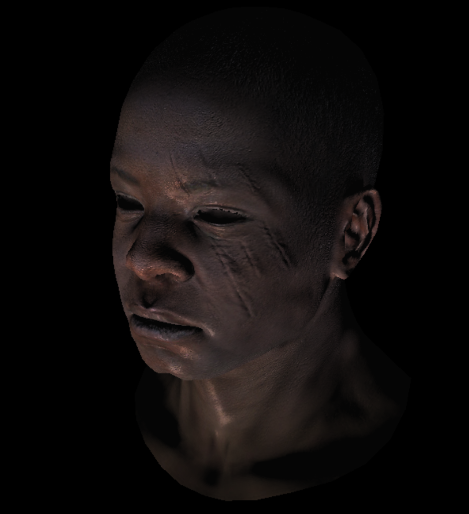
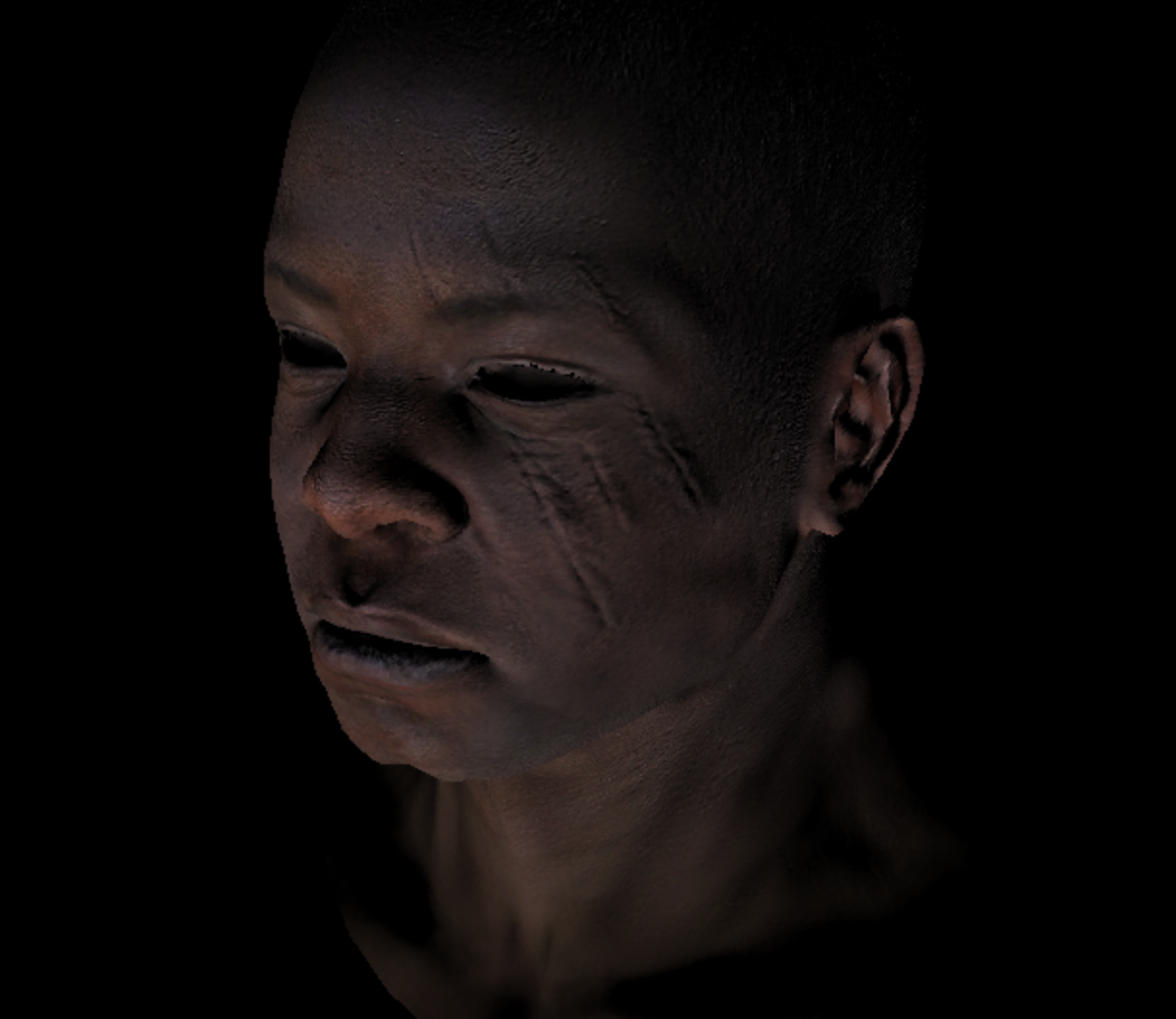
使用法线贴图实现phone模型
- 我们知道对于光照进行插值的方法运算量是很大的,因此为了优化我们需要使用法线贴图
struct NMPhoneShader : public IShader
{
    mat < 2, 3, float > m_varyingUV;
    mat<3, 3, float> m_varyingNormal;

    virtual Vec4f Vertex(int iFace, int nthVert)
    {
        m_varyingUV.set_col(nthVert, g_model->uv(iFace, nthVert));
        m_varyingNormal.set_col(nthVert, proj<3>(g_Projection * g_ModelView.invert_transpose() * embed<4>(g_model->normal(iFace, nthVert), 0.f)));	//法线乘以变换矩阵的逆转置矩阵
        Vec4f m_vertex = embed<4>(g_model->vert(iFace, nthVert)); // read the vertex from .obj file
        return g_Viewport * g_Projection * g_ModelView * m_vertex; // transform it to screen coordinates
    }

    virtual bool fragment(Vec3f bar, TGAColor& color)
    {
        Vec2f uv = m_varyingUV * bar;
        Vec3f bn = (m_varyingNormal * bar).normalize();	//切线空间的法线
        float diff = std::max(0.f, bn * g_LightDir);
        color = g_model->diffuse(uv) * diff;
        return false;                              // whether discard the pixel.true : yes, false : no;
    }
};
-
切线空间
由于需要将世界空间中对应的uv变换到切线空间中进行运算,我们会将这些数据用一个矩阵来表示,因此需要修改一下部分函数
-
shader
//normal mapping & TBN struct NMPhoneShader : public IShader { mat <2, 3, float> m_varyingUV; //存储顶点的纹理坐标 mat <3, 3, float> m_varyingNormal; //存储顶点法线 mat <3, 3, float> m_ndc; //存储透视投影后的三角形坐标 mat <4, 3, float> m_varyingTri; //存储规范化后的三角形坐标 virtual Vec4f Vertex(int iFace, int nthVert) { m_varyingUV.set_col(nthVert, g_model->uv(iFace, nthVert)); //获得纹理坐标 m_varyingNormal.set_col(nthVert, proj<3>((g_Projection * g_ModelView).invert_transpose() * embed<4>(g_model->normal(iFace, nthVert), 0.f))); //获得法线贴图中的法线 Vec4f m_vertex = g_Projection * g_ModelView * embed<4>(g_model->vert(iFace, nthVert)); // read the vertex from .obj file and transfer to erspective projection m_varyingTri.set_col(nthVert, m_vertex); //获得透视投影坐标 m_ndc.set_col(nthVert, proj<3>(m_vertex / m_vertex[3])); //规范化透视投影坐标 return m_vertex; // transform it to screen coordinates } virtual bool fragment(Vec3f bar, TGAColor& color) { Vec2f uv = m_varyingUV * bar; //纹理插值 Vec3f bn = (m_varyingNormal * bar).normalize(); //法线插值 //because transformed from world space to tangen space so use inverse of matrix mat<3, 3, float> A; A[0] = m_ndc.col(1) - m_ndc.col(0); A[1] = m_ndc.col(2) - m_ndc.col(0); A[2] = bn; mat<3,3,float> AI = A.invert(); auto i = AI * Vec3f(m_varyingUV[0][1] - m_varyingUV[0][0], m_varyingUV[0][2] - m_varyingUV[0][0], 0); auto j = AI * Vec3f(m_varyingUV[1][1] - m_varyingUV[1][0], m_varyingUV[1][2] - m_varyingUV[1][0], 0); //get the texture transformed to tangen space mat<3, 3, float>B; B.set_col(0, i.normalize()); B.set_col(1, j.normalize()); B.set_col(2, bn); auto n = (B * g_model->normal(uv)).normalize(); float diff = std::max(0.f, n * g_LightDir); color = g_model->diffuse(uv) * diff; return false; // whether discard the pixel.true : yes, false : no; } }; -
光栅化函数
void rasterization(mat<4, 3, float>& clipc, IShader& shader, TGAImage& image, float* zbuffer) { mat<3, 4, float> pts = (g_Viewport * clipc).transpose(); // 转置使得求得对应点更方便 mat<3, 2, float> pts2; for (int i = 0; i < 3; i++) pts2[i] = proj<2>(pts[i] / pts[i][3]); //包围盒 Vec2f bboxmin(std::numeric_limits<float>::max(), std::numeric_limits<float>::max()); Vec2f bboxmax(-std::numeric_limits<float>::max(), -std::numeric_limits<float>::max()); Vec2f clamp(image.get_width() - 1, image.get_height() - 1); for (int i = 0; i < 3; i++) { for (int j = 0; j < 2; j++) { bboxmin[j] = std::max(0.f, std::min(bboxmin[j], pts2[i][j])); bboxmax[j] = std::min(clamp[j], std::max(bboxmax[j], pts2[i][j])); } } //输出符合条件的像素 Vec2i P; TGAColor color; for (P.x = bboxmin.x; P.x <= bboxmax.x; P.x++) { for (P.y = bboxmin.y; P.y <= bboxmax.y; P.y++) { Vec3f bc_screen = barycentric(pts2[0], pts2[1], pts2[2], P); //插值 //透视矫正 Vec3f bc_clip = Vec3f(bc_screen.x / pts[0][3], bc_screen.y / pts[1][3], bc_screen.z / pts[2][3]); bc_clip = bc_clip / (bc_clip.x + bc_clip.y + bc_clip.z); //对z值插值 float frag_depth = clipc[2] * bc_clip; if (bc_screen.x < 0 || bc_screen.y < 0 || bc_screen.z<0 || zbuffer[P.x + P.y * image.get_width()] > frag_depth) continue; bool discard = shader.fragment(bc_clip, color); if (!discard) { zbuffer[P.x + P.y * image.get_width()] = frag_depth; image.set(P.x, P.y, color); } } } } -
主函数
我们采用命令行参数写入的方式来读取想要的.obj文件。如下图所示,在"命令参数"中填写欲读取的.obj文件
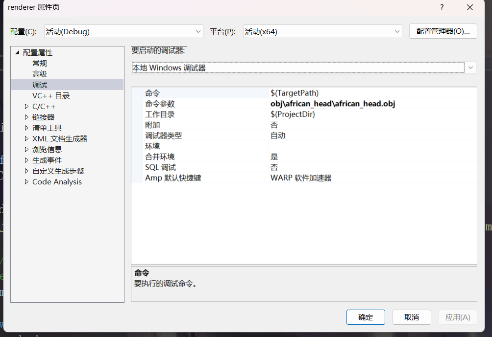
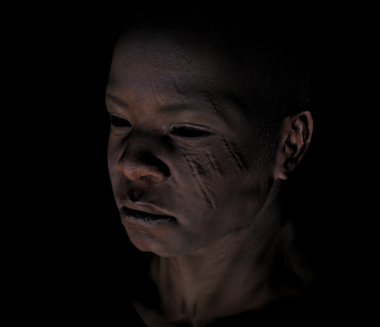
if (2 > argc)
{
    std::cerr << "Usage: " << argv[0] << " obj/model.obj" << std::endl;
    return 1;
}

float* ZBuffer = new float[g_Width * g_Height];
for (int i = g_Width * g_Height; i--; ZBuffer[i] = -std::numeric_limits<float>::max());

TGAImage frameBuffer(g_Width, g_Height, TGAImage::RGB); // the output image
LookAt(g_Camera, g_Target, g_Up);
Projection( -1.f / (g_Camera - g_Target).norm());
ViewPort(g_Width / 8, g_Height / 8, g_Width * 3 / 4, g_Height * 3 / 4);
g_LightDir = proj<3>((g_Projection * g_ModelView * embed<4>(g_LightDir, 0.f))).normalize();

//vert f x/y/z x/y/z x/y/z : x = vertex coord, y = uv coor, z = normal coor
//face : triangle face
for (int m = 1; m < argc; ++m)
{
    g_model = new Model(argv[m]);	//读取模型文件
    NMPhoneShader shader;
    for (int i = 0; i < g_model->nfaces(); ++i)
    {
        for (int j : {0, 1, 2})
        {
            shader.Vertex(i, j);
        }
        rasterization(shader.m_varyingTri, shader, frameBuffer, ZBuffer);
    }
    delete g_model;
}

frameBuffer.flip_vertically();
frameBuffer.write_tga_file("output.tga");

delete[] ZBuffer;
return 0;
输出:
-
reference
https://github.com/ssloy/tinyrenderer/wiki/Lesson-6:-Shaders-for-the-software-renderer

 浙公网安备 33010602011771号