Zephyr学习:DeviceTree学习
参考:
1.详解Zephyr设备树(DeviceTree)与驱动模型 - jayant97 - 博客园
2.Devicetree — Zephyr Project Documentation
硬件: 立创实战派开发板(esp32-s3)
看了大佬写的设备树教程,感觉收获颇丰,赶紧也来巩固一下,哈哈哈。
1. zephyr设备树构建流程
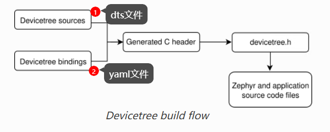
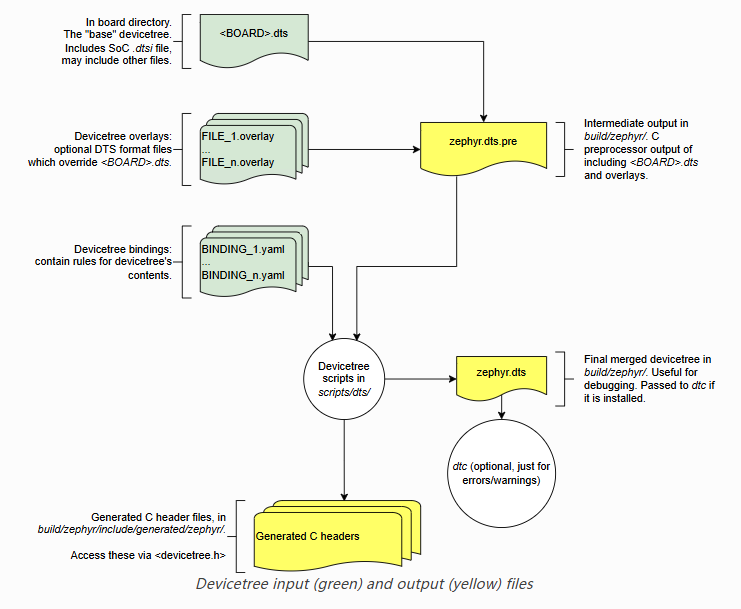
个人理解是我们在dts/overlay中写的硬件信息会通过yaml来确定和那个驱动绑定,然后生成C宏和执行驱动程序。
2. 设备树的结构和语法
参考文档:Syntax and structure — Zephyr Project Documentation
/dts-v1/;

/ {
        a-node {
                subnode_nodelabel: a-sub-node {
                        foo = <3>;
                };
        };
};
/ 表示根节点 ;
a-node 是根节点的一个子节点;
a-sub-node 是 a-node 的一个子节点;
foo 是 a-sub-node 的一个属性;
构建结构一般像这样,从上到下,树形结构:
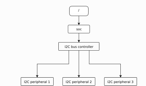
/dts-v1/;

/ {
        soc {
                i2c-bus-controller {
                        i2c-peripheral-1 {
                        };
                        i2c-peripheral-2 {
                        };
                        i2c-peripheral-3 {
                        };
                };
        };
};
一般和外设的地址相关联:
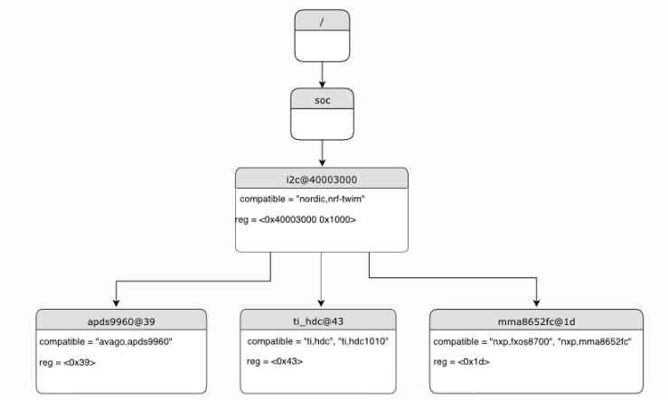
/dts-v1/;

/ {
        soc {
                i2c@40003000 {
                        compatible = "nordic,nrf-twim";
                        reg = <0x40003000 0x1000>;

                        apds9960@39 {
                                compatible = "avago,apds9960";
                                reg = <0x39>;
                        };
                        ti_hdc@43 {
                                compatible = "ti,hdc", "ti,hdc1010";
                                reg = <0x43>;
                        };
                        mma8652fc@1d {
                                compatible = "nxp,fxos8700", "nxp,mma8652fc";
                                reg = <0x1d>;
                        };
                };
        };
};
里面还有很多特殊的地方,需要用到的时候去看官方文档。
3. 设备树的绑定关系
比如我要定义一个按钮,DTS如下:
buttons {
        compatible = "gpio-keys";
        button0: button_0 {
            gpios = <&gpio0 0 (GPIO_PULL_UP | GPIO_ACTIVE_HIGH)>;
            label = "BOOT Button";
            zephyr,code = <INPUT_KEY_0>;
        };
    };
该节点包含一个按钮0子节点,子节点控制一个IO,对应到 GPIO0 的 0 脚,配置成了上拉输入。通过 lable 知道是 Boot 按钮,对应到zephyr里面是第一个按钮。
compatible 属性是用来绑定硬件驱动的;可以知道这个按钮是绑定到 gpio-keys 这个驱动的,然后可以找到 yaml 文件和驱动文件。
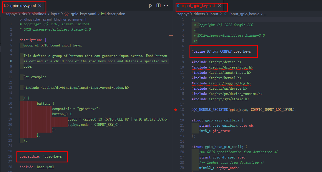
一般 yaml 文件和 compatible 名字是一样的, 驱动文件一般是把短横线变成下划线就可以了。
在gpio-keys.yaml 中可以看到:
compatible: "gpio-keys"

include: base.yaml // 基于base.yaml

properties:
  debounce-interval-ms: // 按键消抖时间
    type: int
    default: 30
    description: |
       Debouncing interval time in milliseconds.
       If not specified defaults to 30.

  polling-mode:  // 使能轮询模式
    type: boolean
    description: |
      Do not use interrupts for the key GPIOs, poll the pin periodically at the
      specified debounce-interval-ms instead.

  no-disconnect: // 断开引脚的功能,用于降低功耗
    type: boolean
    description: |
      Do not try to disconnect the pin on suspend. Can be used if the GPIO
      controller does not support the GPIO_DISCONNECTED flag.
这些参数是可选的,这里没有配置这些参数。
child-binding:
  description: GPIO KEYS child node
  properties:
    gpios: // 配置按钮对应的gpio,上面是对应到GPIO0,上拉输入模式
      type: phandle-array
      required: true // 这个选项是必须要有的

    label:  // 起个别名,上面是对应到boot按键
      type: string
      description: Descriptive name of the key

    zephyr,code: // 对应到zephyr中key的编号,对应值0
      type: int
      description: Key code to emit.
所以,在写dts的时候可以参考yaml的描述来写。
在驱动程序gpio_keys.c中可以看到以下的函数:
gpio_keys_poll_pin
gpio_keys_poll_pins
gpio_keys_change_deferred
gpio_keys_interrupt
gpio_keys_interrupt_configure
gpio_keys_init
gpio_keys_pm_action
这些函数实现了yaml中描述的消抖功能,轮询功能等等。
最终在初始化时调用宏函数GPIO_KEYS_INIT(i)执行初始化。
#define GPIO_KEYS_INIT(i)                                                                          \
    DT_INST_FOREACH_CHILD_STATUS_OKAY(i, GPIO_KEYS_CFG_CHECK);                                 \
                                                   \
    static const struct gpio_keys_pin_config gpio_keys_pin_config_##i[] = {                    \
        DT_INST_FOREACH_CHILD_STATUS_OKAY_SEP(i, GPIO_KEYS_CFG_DEF, (,))};                 \
                                                   \
    static struct gpio_keys_pin_data                                                           \
        gpio_keys_pin_data_##i[ARRAY_SIZE(gpio_keys_pin_config_##i)];                      \
                                                   \
    static const struct gpio_keys_config gpio_keys_config_##i = {                              \
        .debounce_interval_ms = DT_INST_PROP(i, debounce_interval_ms),                     \
        .num_keys = ARRAY_SIZE(gpio_keys_pin_config_##i),                                  \
        .pin_cfg = gpio_keys_pin_config_##i,                                               \
        .pin_data = gpio_keys_pin_data_##i,                                                \
        .handler = COND_CODE_1(DT_INST_PROP(i, polling_mode),                              \
                       (gpio_keys_poll_pins), (gpio_keys_change_deferred)),        \
        .polling_mode = DT_INST_PROP(i, polling_mode),                                     \
        .no_disconnect = DT_INST_PROP(i, no_disconnect),                                   \
    };                                                                                         \
                                                   \
    static struct gpio_keys_data gpio_keys_data_##i;                                           \
                                                   \
    PM_DEVICE_DT_INST_DEFINE(i, gpio_keys_pm_action);                                          \
                                                   \
    DEVICE_DT_INST_DEFINE(i, &gpio_keys_init, PM_DEVICE_DT_INST_GET(i),                        \
                  &gpio_keys_data_##i, &gpio_keys_config_##i,                          \
                  POST_KERNEL, CONFIG_INPUT_INIT_PRIORITY, NULL);

DT_INST_FOREACH_STATUS_OKAY(GPIO_KEYS_INIT)

 浙公网安备 33010602011771号