Help document of CAD Plus
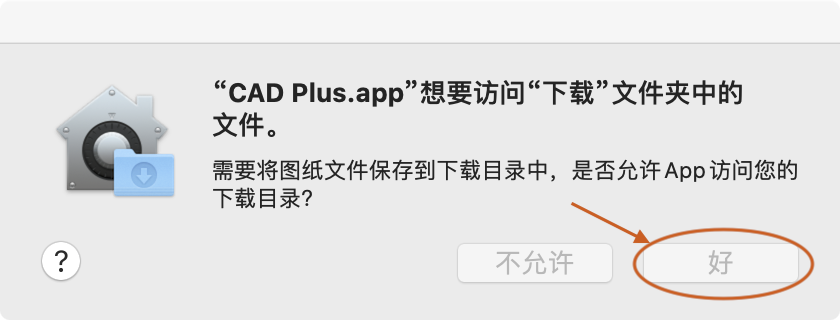
1. Permission request
The app need to read and write the Downloads directory; the drawing which to be opened should in the Downloads directory, the app will open it from the Downloads directory and will save the Drawing file to the Downloads directory. so you need to allow the app to access the Downloads directory.
2. Commands usage help
When a command is being executed, input 'u' or "undo" to cancel the current state of the command and return the command to the previous state; Enter a space to complete the execution of the command; input "cancel" or "esc" to cancel the execution of the command; Letters in commands are not case sensitive
2.1 ALL (List all commands)
List all commands of CAD Plus; With the upgrade of APP version, the command functions will continue to be enriched and improved.
2.2 PO (Draw a point)
Draw a point
- Draw a point based on coordinate
- Draw points according to the intersection of 2 Curves
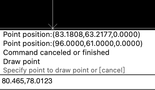
2.2.1 Specify point coordinates to draw points
Click the mouse in the drawing view or input coordinates in the command box to add a point to the drawing.
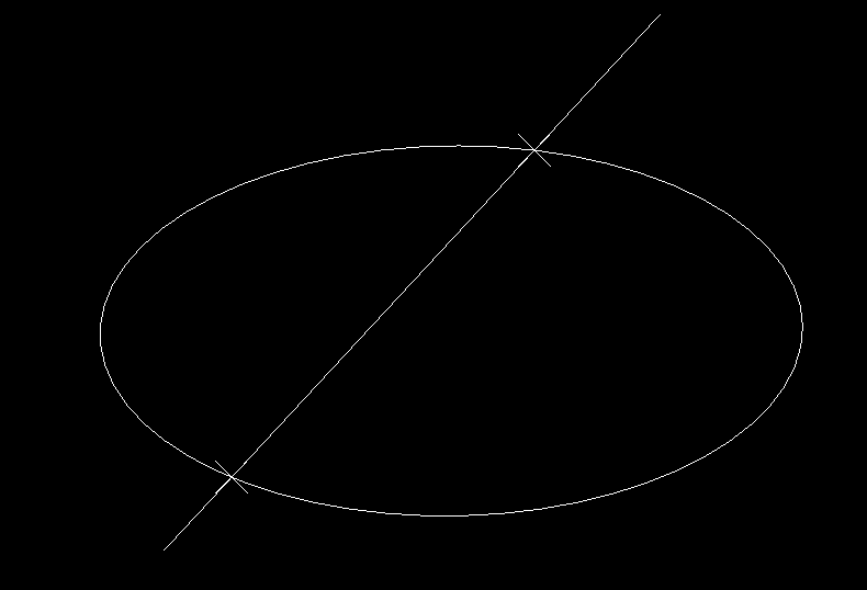
2.2.2 Draw intersection points of 2 Curves
Input 'R' or press the spacebar, select 2 curves and draw the intersection points of the 2 curves; Note: the two curves must be on the same plane
2.3 L (Draw a line segment)
Draw a line segment
- Draw a line segment by 2 points
- Draw a line segment by start point, length, angle
- Draw a line segment perpendicular to a specified line
- Draw a line segment with an angle value to a specified line
- Draw a line segment parallel to a specified line
- Draw the common tangent of 2 circles
- Draw a line by start point, direction and length
- Draw an Orthogonal line
2.3.1 Specify start point
Input the point coordinates in the command box or click mouse in the drawing view to specify the starting point. If the last added entity is a linear entity, enter the space will take the end point of the last linear entity as the starting point of the new line segment.
2.3.2 Specify next point or determine the next point according to the length and angle
Note: the length must be >0, otherwise the value is invalid
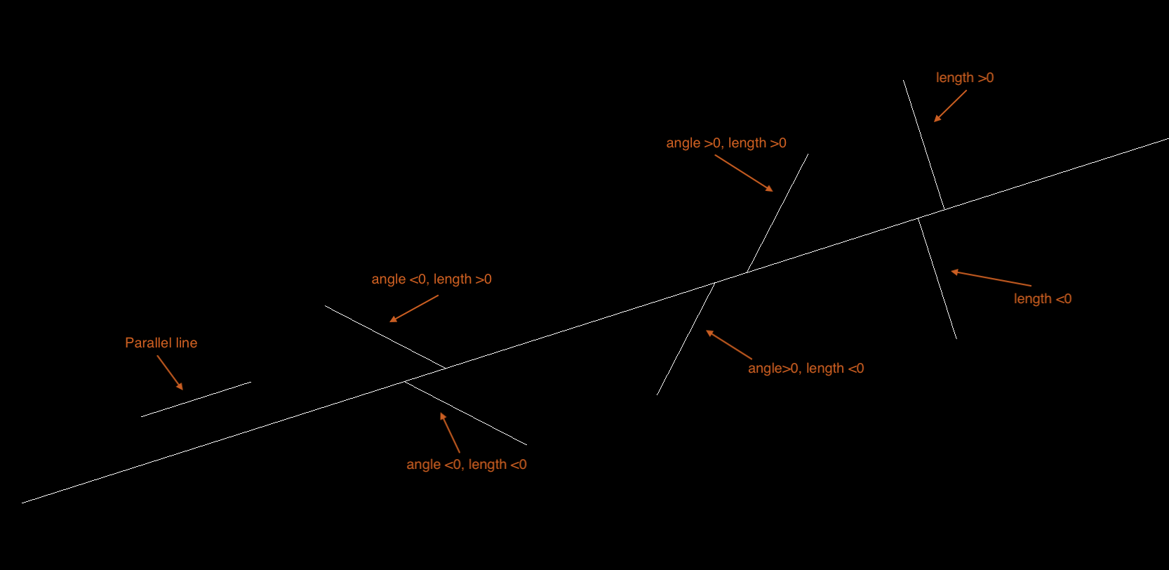
After the length is set, input an angle in the command box to determine the endpoint of the line segment. Note: the endpoint of the line segment with an angle >0 rotates counterclockwise along the X axis, < 0 rotates clockwise along the X axis, =0 is parallel to the X axis

2.3.3 End drawing or close drawn line segments
Enter a space or "cancel" in the command box to end the drawing of the line segment; If there are more than 2 added segments, enter 'C' or "close" to close and end the command

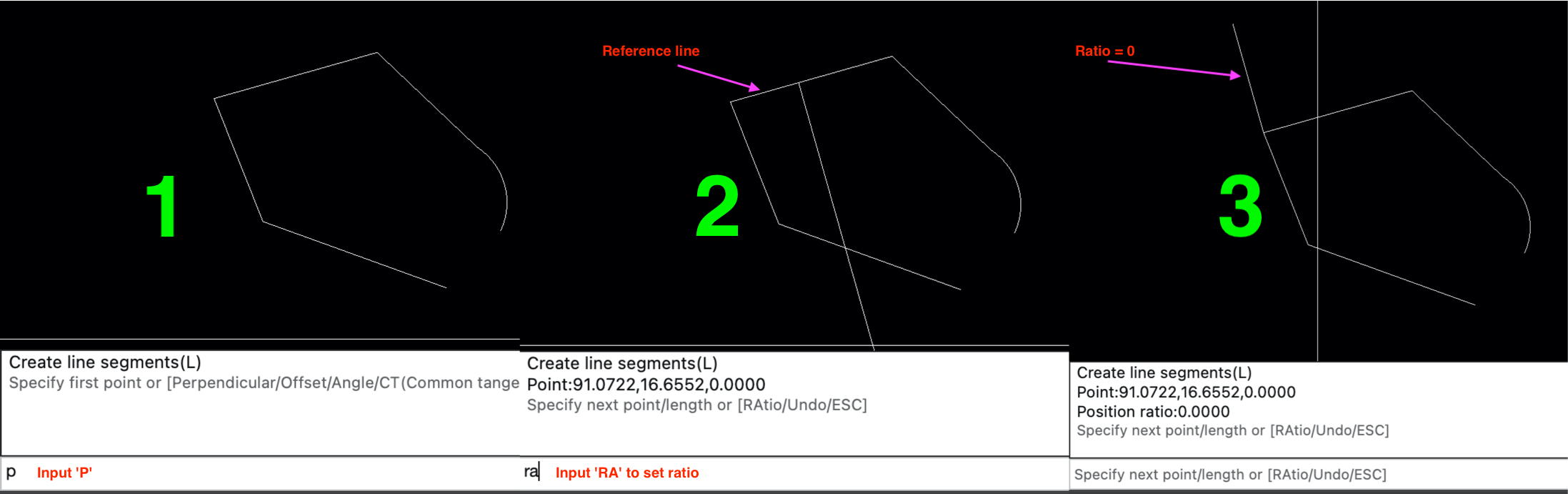
2.3.4 Draw a line segment perpendicular to a specified line
Input 'p' to start drawing a line segment that are perpendicular to a linear entity (linear entities can be a xline, ray, line segment, or linear part of a polyline); If the reference line is a segment, a polyline or multiline can specify the ratio of insertion position (0<= ratio <=1), position ratio=0 is inserted at the beginning of the reference line, or position ratio=1 is inserted at the end of the reference line. length can be >0 or <0
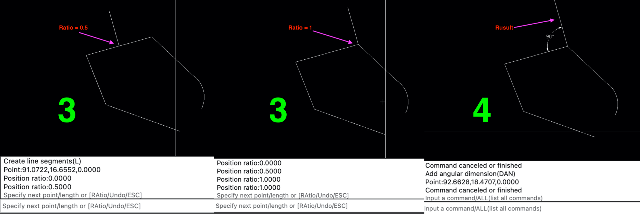
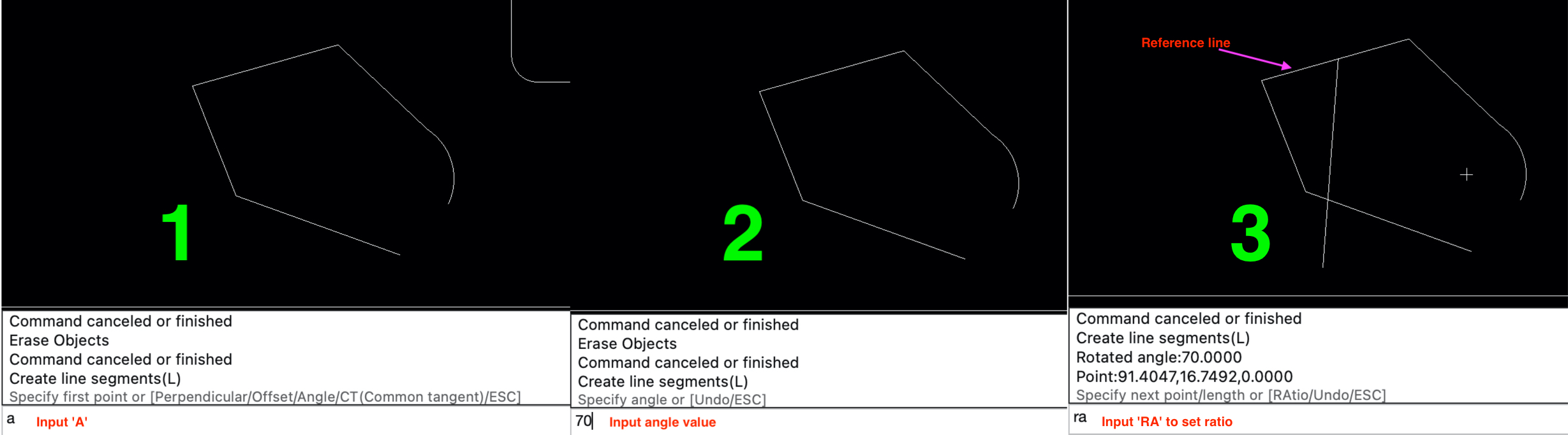
2.3.5 Draw a line segment with an angle value to a specified line
Input 'a' to start drawing a line segment at an angle with a linear entity; If the reference line is a segment, a polyline or multiline can specify the ratio of insertion position (0<= ratio <=1), position ratio=0 is inserted at the beginning of the reference line, or position ratio=1 is inserted at the end of the reference line. length can be >0 or <0, angle can be >0, =0 or <0

2.3.6 Draw a line segment parallel to a specified line
Input 'o' to start drawing a line segment parallel to a linear entity. offset must be >=0, length can be >0 or <0
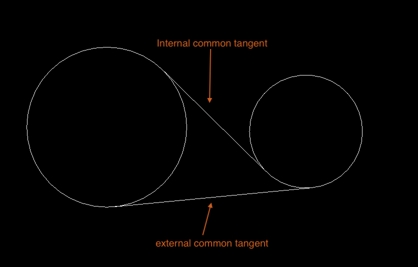
2.3.7 Draw the common tangent of 2 circles
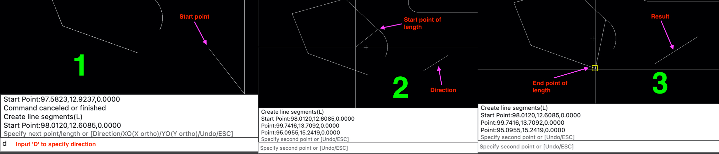
2.3.8 Draw a line by start point, direction and length
- Specify start point
- Specify direction, Enter 'D' or press the spacebar to set the direction
- Specify length; The length of the line can be inputed or determined by specifying 2 points with the mouse; Length>0
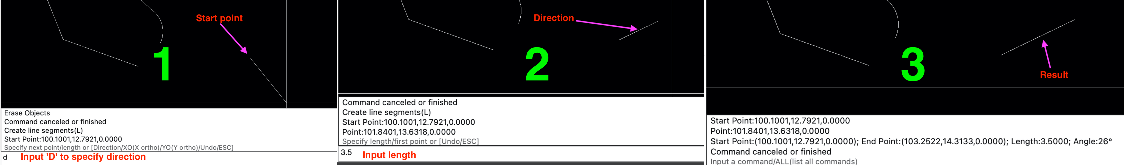
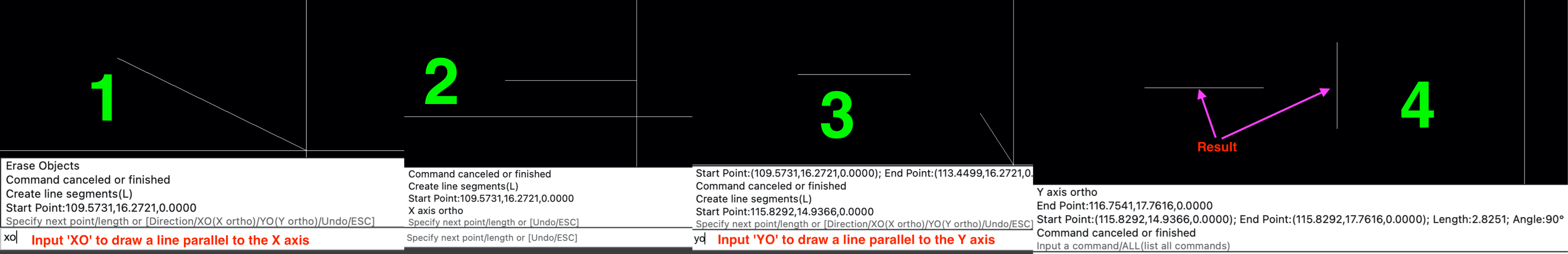
2.3.9 Draw a Orthogonal line
After specifying the starting point, input 'XO' to draw a line segment parallel to the X axis, and input 'YO' to draw a line segment parallel to the Y axis
2.4 PL (Draw a polyline)
Draw a polyline
1. Add line segment
- Add line segment by vertex point
- Add line segment by length and angle
- Add line segment by direction and length
2. Add arc segment
- Add arc segment by radius and arc angle
- Add arc segment by center point and arc angle
- Add arc segment by 3 points
- Add arc segment by center, length, and direction
- Add arc segment by radius, length, and direction
2.4.1 Specify start point
Input the point coordinates in the command box or click mouse in the drawing view to specify the starting point. If the last added entity is a linear entity, enter the space will take the end point of the last linear entity as the starting point of the new polyline.
2.4.2 Specify next point
- Input the point coordinates in the command box or click the mouse in the drawing view to determine the next endpoint
- Input the length and angle in the command box to add a new vertex; Note: the length must be >0, the angle >0 rotates counterclockwise along the X axis, the angle =0 is parallel to the X axis, and the angle <0 rotates counterclockwise along the X axis
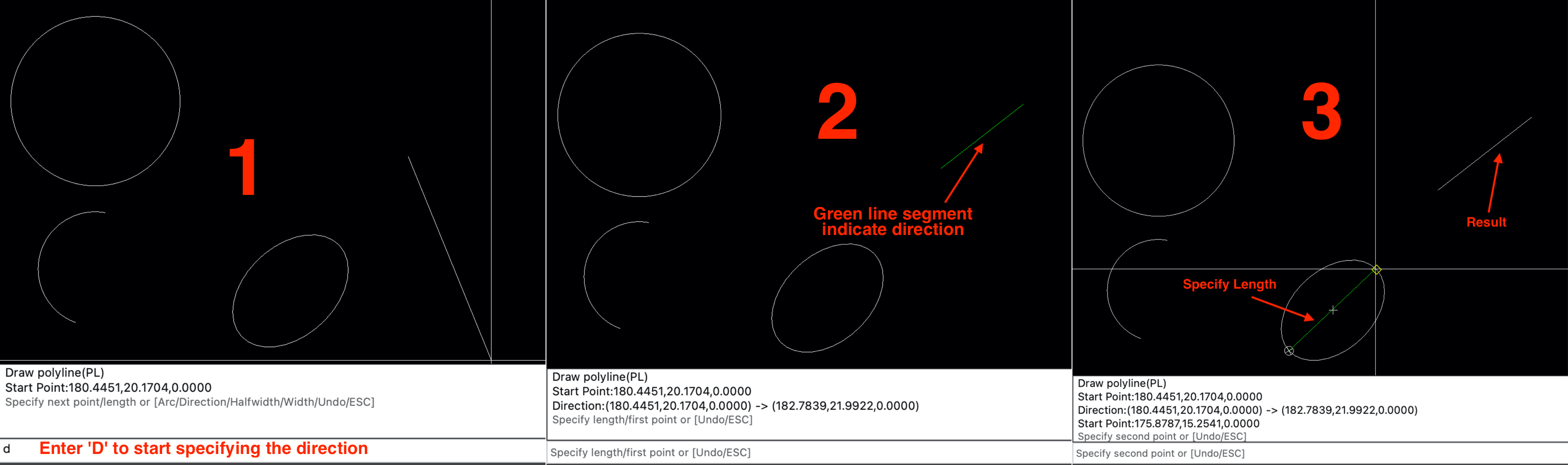
2.4.2.1 Add line segment by direction and length
Pressing the SHIFT key while drawing the direction can orthogonally draw the direction
2.4.3 Add arc segment
Input 'A' to add arc segment when specify next point
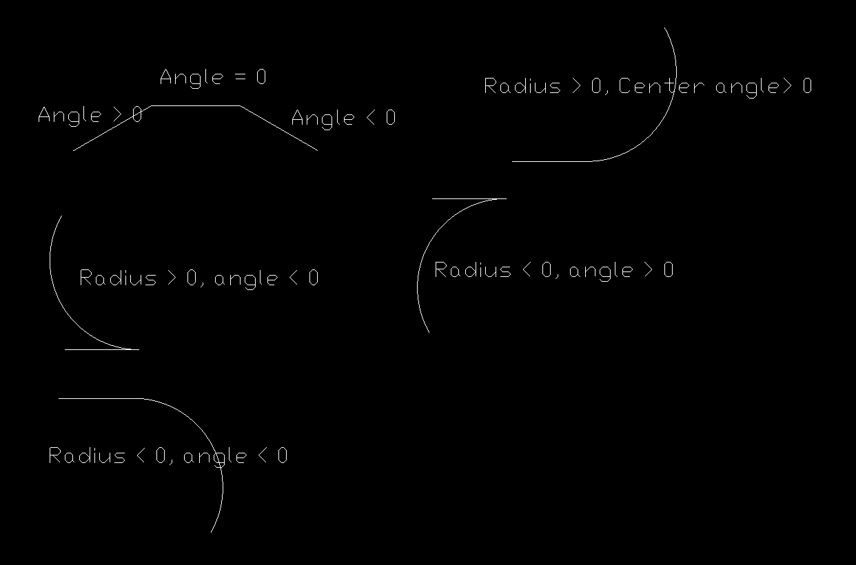
2.4.3.1 Add arc segment by radius and arc angle
- Input radius of arc; Note:radius can't be 0, If the radius is>0, the center of the arc is located 90 degrees counterclockwise of the starting point tangent; if the radius is<0, the center of the arc is located 90 degrees clockwise of the starting point tangent.
- Input arc angle(center angle); Note: 0 < |arc angle| < 360, center angle>0 rotates counterclockwise, center angle<0 rotates clockwise
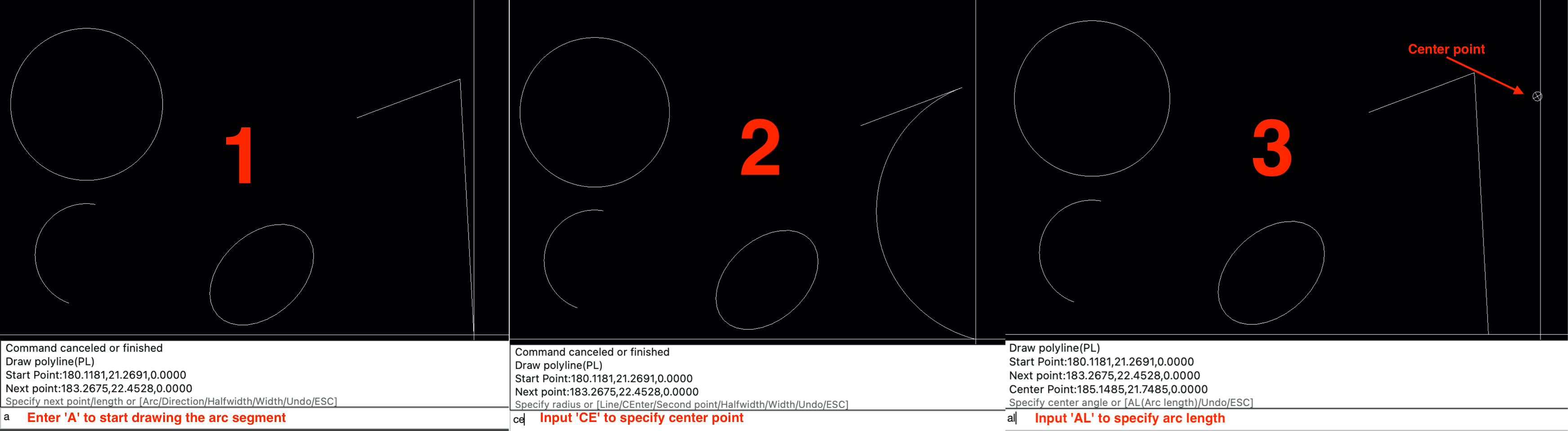
2.4.3.2 Add arc segment by center point and arc angle
- Input 'CE' to specify center point
- Input arc angle(center angle); Note: 0 < |arc angle| < 360, center angle>0 rotates counterclockwise, center angle<0 rotates clockwise
2.4.3.3 Add arc segment by 3 points
Input 'S' specify second point of the arc then specify end point to add the arc segment
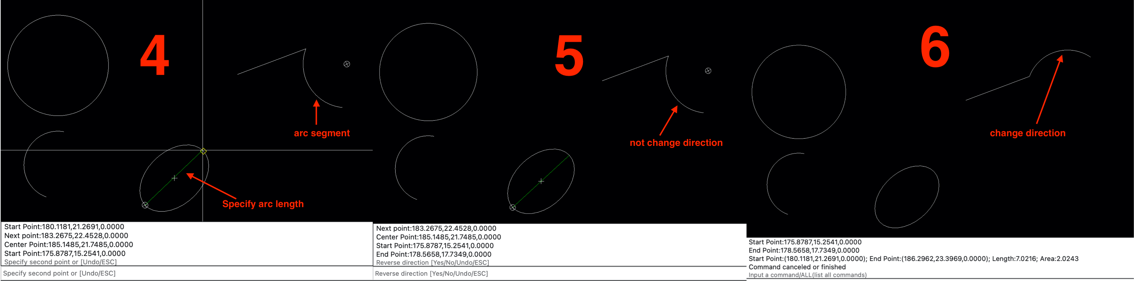
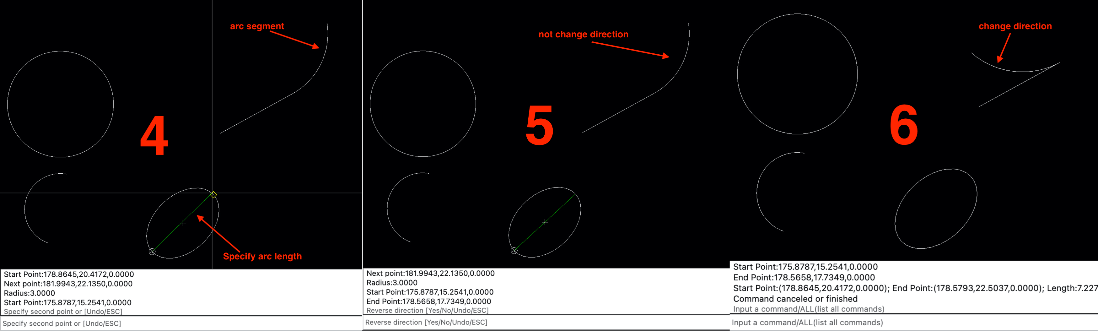
2.4.3.4 Add arc segment by center, length, and direction
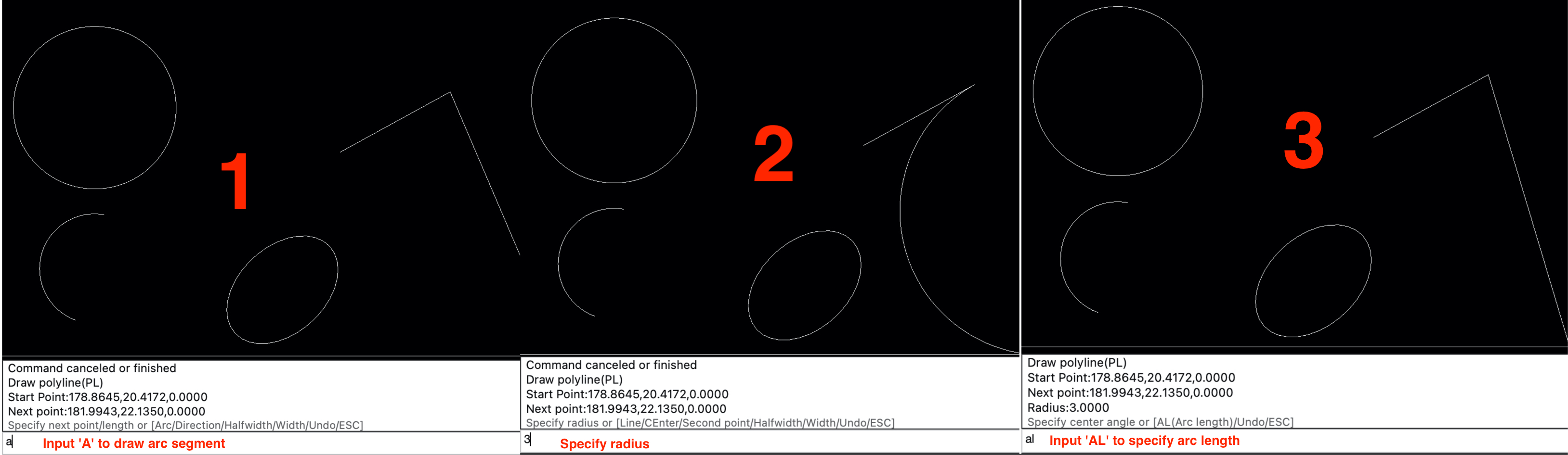
2.4.3.5 Add arc segment by radius, length, and direction ![]()
2.4.4 Set segment properties
The line between the two vertices of a polyline is called segment. When drawing a polyline, you can set start width, and end width of the segment.
2.4.4.1 Set width or halfwidth
The width of each segment is determined by the start width and end width, and the half width is the width /2; input 'w' to set the width, and input 'h' to set the half width. Note: width or half width must be > = 0
Default width is 0
If there are more than 3 vertices in the polyline, enter 'C' to close the polyline and complete the command.
2.5 C (Draw a Circle)
Draw a Circle
- Draw a circle by center and radius
- Draw a circle by center and diameter
- Draw a circle by 3 points on the circle
- Draw a circle according to the 2 end points of the diameter
- TTR (tangent, tangent, radius) draw a circle
- TR (tangent, radius) draw a circle
2.5.1 center point, radius/diameter draw circle
- Specify center point, input the center point in the command box or click the mouse in the drawing view to specify the center point
- Input the value of radius in the command box or move the mouse in the drawing view and click to determine the radius; Radius must be > 0
- When setting the radius, input 'D' in the command box to specify the diameter; Diameter must be > 0
2.5.2 Draw circle by 3 points
When specifying the center point, input "3P" to switch to 3-points method to draw a circle. the 3 points cannot be on the same line
2.5.3 Draw circle by 2 points
When specifying the center point, input "2p" to switch to the 2-point method to draw a circle; two points are the two endpoints of the diameter
2.5.4 Draw circle by tangent point, tangent point, radius
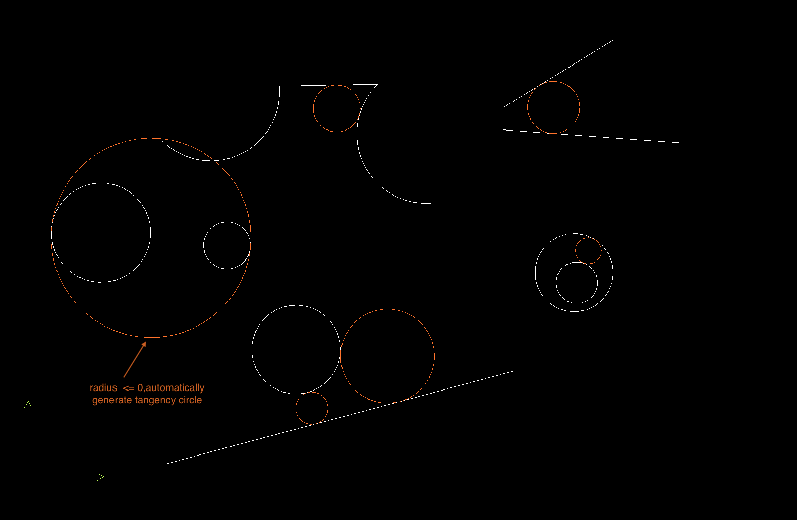
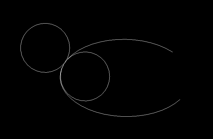
When specifying the center of the circle, input "TTR" to switch to the tangent point, tangent point, radius method to draw a circle; tangent entity could be arc, line, xline, polyline, ray or circle. when two tangent entities are circle or arc and specify radius <=0, then the third circle will be automatic generated.
2.5.5 Draw a circle by TR (tangent, radius)
When specifying the center of a circle, input 'tr' to switch to the tangent point, radius to draw a circle; The entity of tangent point can be circle, arc, xline, line segment, ray, polyline, ellipse; If the tangent is a xline or a ray, you can directly set the radius to complete the drawing of the circle. For other curves, you need to specify the location of the tangent point and then specify the radius. 0 < = position ratio < = 1, 0 represents the start point of the curve, 1 represents the end point
2.6 EL (Draw a Ellipse)
Draw a Ellipse; When there is no need to set the angle of the elliptical arc after the ellipse is drawn, you can enter a space or 'F' in the command box to complete the command
2.6.1 center, end point of axis 1, radius of axis 2 to draw a ellipse
- Input the center point in the command box or click the mouse in the drawing view to specify the center point
- Input the endpoint of axis 1 radius in the command box or click the mouse in the drawing view to specify the endpoint of axis 1
- Input the radius of axis 2 in the command box. The radius value must be >0
2.6.2 center, axis 1 radius, axis 1 radius angle, axis 2 radius draw a ellipse
- Input the center point in the command box or click the mouse in the drawing view to specify the center point
- When specifying the axis end point, input a double value to set the radius of axis 1; Axis 1 radius must be >0
- Input the angle of the radius of axis 1 in the command box; Angle >0 rotates counterclockwise along X axis, angle <0 rotates clockwise along X axis
- Input the radius of axis 2 in the command box; Radius value must be > 0
2.6.3 two endpoints of axis 1 and the radius of axis 2 draw a ellipse
- When specifying the center point, input "AP" or press the spacebar to switch to specify the two endpoints of setting axis 1
- Input the two endpoints of axis 1 in the command box or click the mouse in the drawing view to specify the two endpoints of axis 1
- Input the radius of axis 2 in the command box; Radius value must be > 0
2.6.4 Set start angle, end angle, arc angle
- After draw the ellipse, input the starting angle in the command box to specify the starting angle of the arc
- After specify the start angle, input the end angle to complete the drawing of the arc
- When specifying the end angle, input "CA" to switch to setting the arc angle (center angle) of the arc to complete the drawing of the arc
2.7 A (Draw an arc)
Draw an arc
2.7.1 Draw an arc by 3-points
Input 3 points on the arc to complete the drawing of the arc. Note: 3 points cannot be on the same line
2.7.2 Center, radius, start angle, end angle to draw an arc
- When specifying the first point, input 'C' to set the center point
- After setting the center point, input the radius value to set the radius of the arc. Note: the radius must be > 0
- Input the starting angle of the arc after setting the radius
- Input the end angle to end the drawing of the arc
2.7.3 Center, radius, start angle, arc length to draw an arc
When specifying the end angle, input 'L' and enter the arc length to complete the drawing of the arc
2.7.4 Center, radius, start angle, arc angle to draw an arc
Input "CA" when specifying the end angle, and then input the angle value to complete the drawing of the arc
2.7.5 Center point, start point, arc length / end angle / arc angle draw arc
- When specifying the first point, input 'C' to set the center point
- After setting the center point, input the starting point coordinates or click the drawing view to determine the starting point of the arc
- After setting the starting point, input the arc length or input "EA" to specify the end angle; input "CA" to specify the center angle of the arc
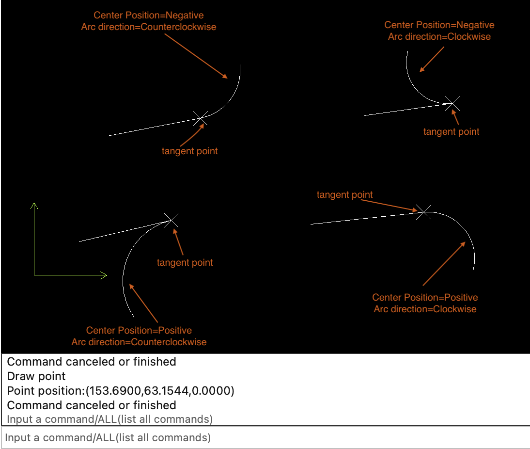
2.7.6 Tangent point, radius draw an arc
If the entity last added to the drawing is a curve, press the space or input "CO" at the beginning of the command to take the end point of the previous curve as the tangent point and starting point of the arc
- Set the position of the center, where the center position indicates whether the center is in the positive or negative direction of the tangent
- Set the radius of the arc; Radius value must be > 0
- After setting the radius, set the end angle of the arc, input 'L' to switch to input arc length, and input "CA" to switch to the setting center angle
2.7.7 Set the direction of an arc
When the arc is drawn, you can set the direction of the arc, input "cw" = draw clockwise, "ccw" = draw counterclockwise.
2.8 REC (Draw a rectangle)
Draw a rectangle
- Draw a rounded rectangle
- Draw a rectangle according to 2 diagonal points of the rectangle
- Draw a rectangle by start point, length, width
- Draw rectangle by start point, area, one side length
- draw rectangle by start point, perimeter, one side length
2.8.1 Start point, diagonal point to draw a rectangle
Input the starting point in the command box, and the diagonal point to draw a rectangle
2.8.2 Start point, length, width to draw a rectangle
- After setting the starting point, directly input the length value when setting the second inflection point to set the length of the rectangle. Note: the length must be > 0
- After setting the length, input the width value to set the width of the rectangle. The width value must be > 0
2.8.3 Start point, area, side 1 length to draw a rectangle
After setting the start point, input 'a' or "area" to specify the area when setting the second inflection point. Note: the area must be >0
Input the length of one side to draw a rectangle. Note: the side length must be >0
2.8.4 Start point, perimeter, side 1 length to draw rectangle
After setting the start point, input 'p' to specify the perimeter when setting the second inflection point. Note: the perimeter must be >0
Input the length of one side to draw a rectangle. Note: the side length must be >0
2.8.5 Draw a rounded rectangle
When specifying the starting point, input 'ft' to set the radius of the rectangle. The radius must be >=0
2.8.6 Set the line width or angle of the rectangle
When a rectangle is drawn, input the line width or "ang" to set the rotation angle of the rectangle. Note: the line width must be > =0, the angle >0 rectangle rotates counterclockwise around the start point, and the angle < 0 rectangle rotates clockwise around the start point
2.9 POL (Draw a regular polygon)
Draw a regular polygon
- Draw a polygon by insertion point, side's length and sides' number
- Draw a polygon by sides' number, center point and radius
- Draw a polygon by sides' number and endpoints of side
2.9.1 Specify the insertion point, side length, and the number of sides of the polygon
Side length must be >0; The number of sides must be > = 3
2.9.2 Set the line width or angle
When a regular polygon is drawn, input the line width or "ang" to set the rotation angle of the regular polygon. Note: the line width must be > =0, the angle >0 polygon rotates counterclockwise around the start point, and the angle < 0 rectangle rotates clockwise around the start point
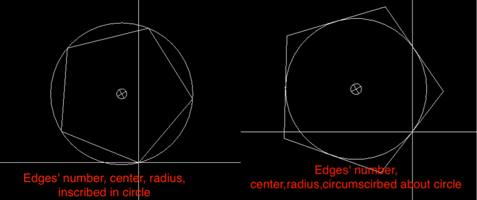
2.9.3 Draw a polygon by sides' number, center point and radius
- Input an integer number(>= 3)to specify the sides' number when specify insertion point
- Click mouse or input a point to specify the center point
-
Set the relationship between polygon and its circle; 'I' inscribed in circle, 'C':circumscirbed about circle
- Input the radius or click mouse in drawing to add polygon
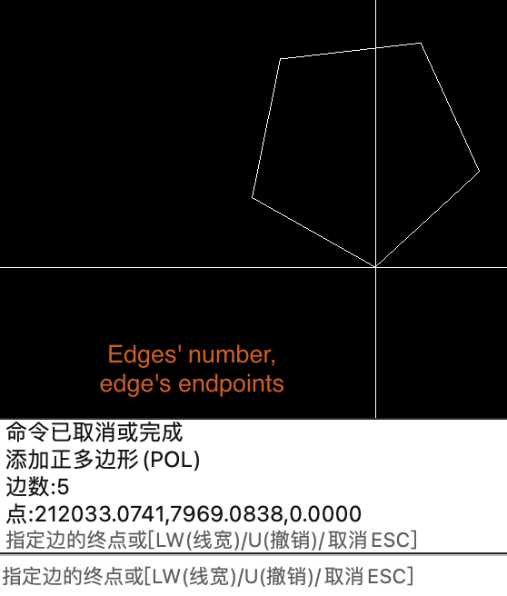
2.9.4 Draw a polygon by sides' number and endpoints of side
- Input an integer number(>= 3)to specify the sides' number when specify insertion point
- Input 'E' to specify endpoints of side when specifying center point
2.10 T (Add a Single line text)
Add a Single line text
2.10.1 Set content of the text
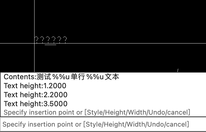
When setting text content, you can set text style, text width, height and other attributes; To add a special symbol, you need to select the text. Note: press enter after input the text content; If the text is displayed as "?" It indicates that the style of the text is incorrect, so it is important to set the correct text style in order to display the text normally

If you want to add an overline or underline to the text, you need to select the text you want to add first
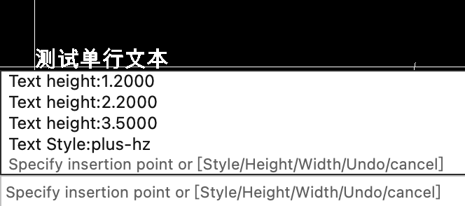
2.10.2 Specify the text insertion point, set the text style, height, width
Before inserting text, you can input 's' to modify the style of the text, input 'h' to adjust the height, and input 'w' to adjust the width
Wrong text style
Correct text style
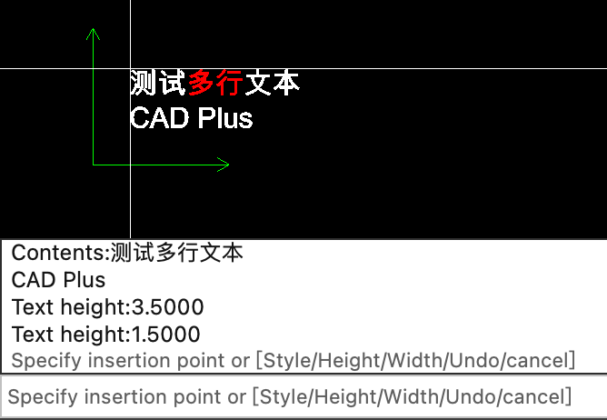
2.11 MT (Add multiline text)
Add multiline text
2.11.1 Specify the text insertion point, set the text style, height, width
When setting the text content, you can set the text style, width, height and other attributes of the text. To add special symbols and colors, you need to select the text. Note: press enter after input the text content; If the text is displayed as "?" It indicates that the style of the text is incorrect, so it is important to set the correct text style in order to display the text normally
2.11.2 Specify the text insertion point, set the text style, height, width
Before inserting text, you can input 's' to modify the style of the text, input 'h' to adjust the height, and input 'w' to adjust the width; Height must be >0, width > = 0. If it is 0, the width is adaptive.
2.12 DAL (Add Aligned dimension)
Add Aligned dimension, Aligned dimensions are used to measure the length between 2 vertices or 2 points of a linear solid
When setting the first extension point, input 's' or press spacebar to select a linear entity and add dimension to it; During the drawing process, input "DS" to set the dimension style, "TS" to set the text style, "Si" or press spacebar to set the size of the text, 'a' to set the text angle, and "SC" to set the scale of the dimension. Text size must be > 0; Scale must be > 0
2.13 DLI (Add Rotated dimension)
Add Rotated dimension, Rotated dimension is used to measure the projection distance of 2 points on the x-axis or y-axis
When setting the first extension point, input 's' to select a linear entity and add dimension to it; During the drawing process, input "DS" to set the dimension style, "TS" to set the text style, "Si" to set the size of the text, 'a' to set the text angle, and "SC" to set the scale of the dimension. input 'x' to dimension the projection length of the X axis, and input 'y' to dimension the projection length of the Y axis;Text size must be > 0; Scale must be > 0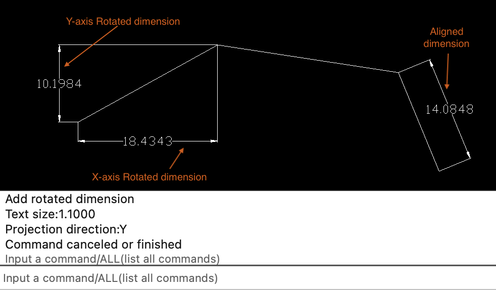
2.14 DAN (Add Angular dimensions)
Add Angular dimensions; you can add an angular dimension for arc, arc segment of polyline, 2 intersecting lines, or 3 points.
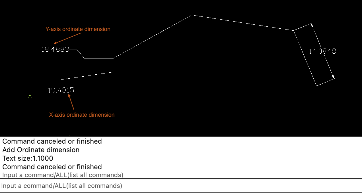
2.15 DIMO (Add ordinate dimension)
Add ordinate dimension; ordinate dimension is used to specify the X or Y coordinates of a point; input 'x' to specify the x-axis coordinates, and input 'y' to specify the y-axis coordinates; The default is to specify the X coordinate
2.16 DDI (Add Diametric dimension)
Add Diametric dimension; you can add a diametric dimension for an arc, arc segment of a polyline or a circle.
When drawing a dimension, input "DS" to set the dimension style, "TS" to set the text style, "Si" to set the text size, 'a' to set the text angle, "SC" to set the scale, "cm" to set the center mark size, "SF" to show forced line, and "HF" to hide forced line.
2.17 DAR (Add Arc dimension)
Add Arc dimension;you can add an arc dimension for an arc, arc segment of a polyline.
2.18 DJO (Add Radial large dimension)
Add Radial large dimension; you can add a radial large dimension for an arc, arc segment of a polyline or a circle.
2.18.1 Specify override center
Override center is the other endpoint of the dimension line.
2.18.2 Specify Chord point
Chord point represent point marked on a circle or arc; When specifying chord point, input "DS" to set the dimension style, "TS" to set the text style, "Si" to set the text size, 'a' to set the text angle, "SC" to set the scale, "JP" to specify the jog point, and "JA" to specify the jog angle
2.19 DRA (Add Radial dimension)
Add Radial dimension; you can add a radial dimension for an arc, arc segment of a polyline or a circle.
When drawing a dimension, input "DS" to set the dimension style, "TS" to set the text style, "Si" to set the text size, 'a' to set the text angle, "SC" to set the scale, "cm" to set the center mark size, "SF" to show forced line, and "HF" to hide forced line.
2.20 LE (Add leader)
Add leader; you can add a leader for mline, tolerance, block reference
When adding a leader, input "SP" to set it as spline, "PL" polyline; input "DS" to set the dimension style; input "SA" to display the arrow, "ha" to hide the arrow; input 'f' to end the drawing of the leader
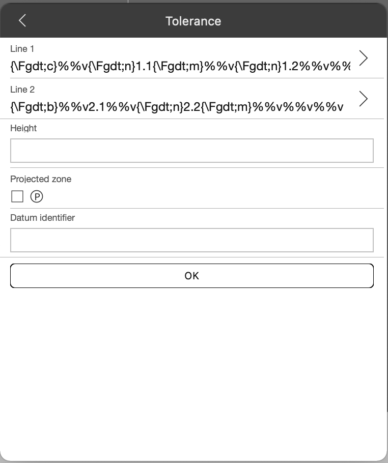
2.21 TOL (Add tolerance)
Add tolerance
2.21.1 Set text of a tolerance
2.21.2 Add leader for tolerance
After setting the tolerance text, start adding a leader to the tolerance, and you can add 2 vertices to the leader
2.21.3 Specify the location of the tolerance
When the leader of tolerance is set or when adding the leader, input 'L' will set the position of tolerance
When setting the position of tolerance, input "DS" to set the dimension style of tolerance and leader; input "ts" to set the text style of tolerance; input "Si" to set the text size of the tolerance; input "SC" to set the scale of the tolerance.
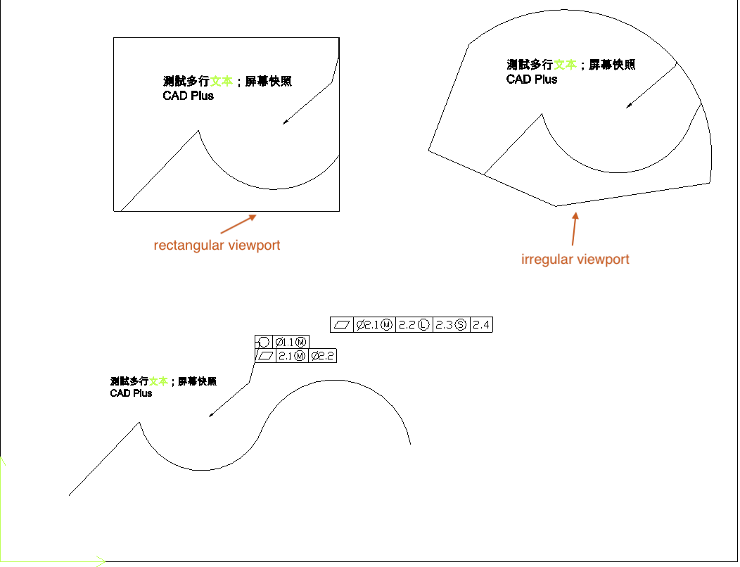
2.22 MV (Add or setup a viewport)
Add or setup a viewport, This command can only be operated in paper layout space
2.22.1 Add a rectangular viewport
Rectangular viewports can be added by specifying 2 diagonals of the viewport
2.22.2 Add a irregular viewport
First, add an irregular closed curve to a paper layout; Then input "MV" command, then input 'o' and select the closed curve created
2.22.3 Set parameters for viewport
When setting the viewport after creation, input "on" to open the viewport, "off" to close the viewport; 'a' to set angle; 's' to set scale
2.23 TB (Add table)
Add table, you can import table from a json file or an excel file
2.23.1 Specify location of the table
After importing from JSON or excel file successfully, you can specify the insertion position of the table
2.23.2 Set table properties
Input 'w' to set width of the table; 'h' to set height of the table; 's' to set the table style; "CW" to set the column width. Column width format: "column index, width value". For example, to set the width of the second column to 3.6, input 2,3.6. To set all column widths, input 0,3.6; input "RH" to set the row height, row height format: row index,height value. For example, to set the row height of the first row to 3.5, input 1,3.5, and to set all row heights to 3.5, input 0,3.5
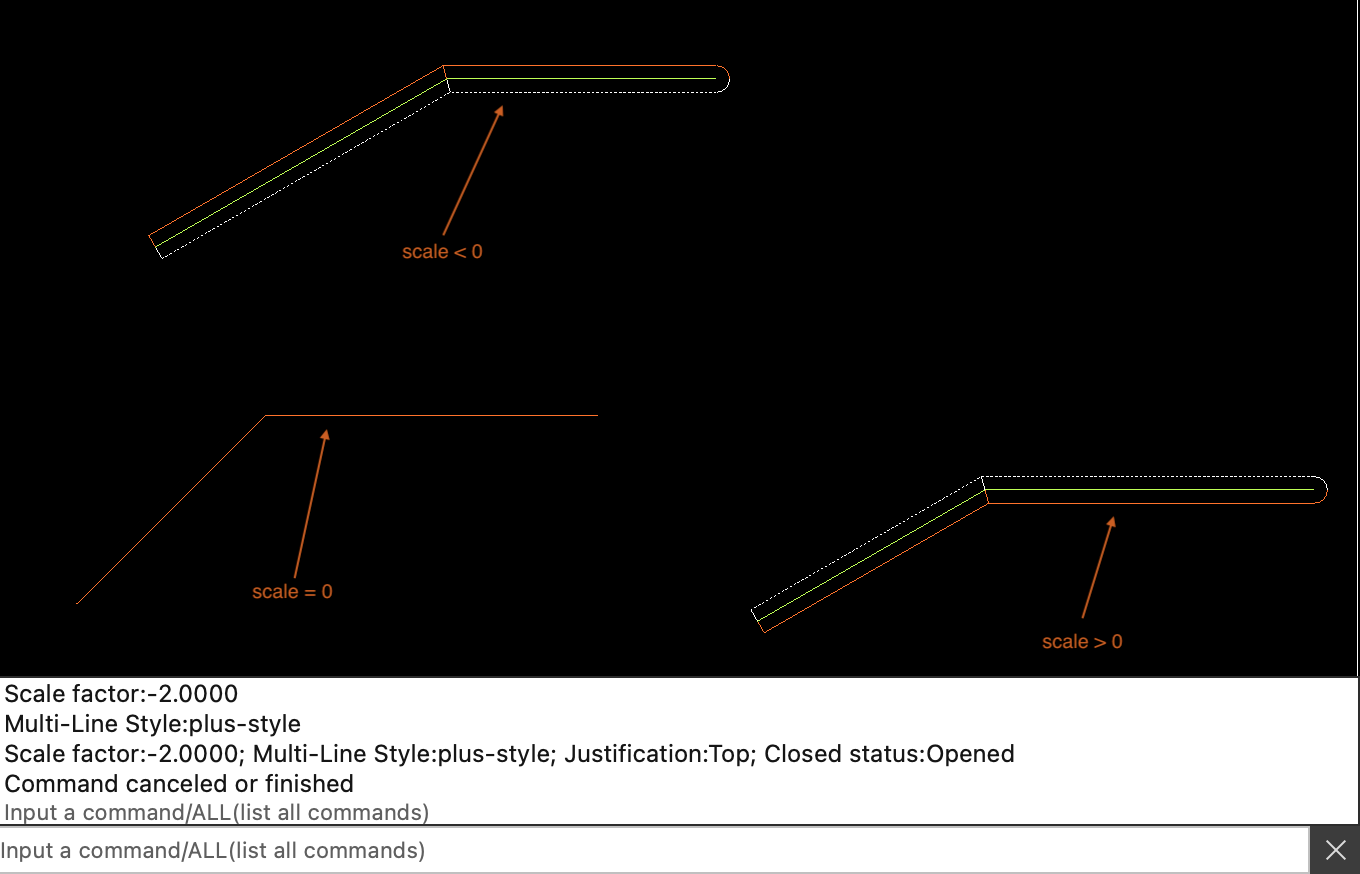
2.24 ML (Add multi-line)
Add multi-line
2.24.1 Set multi-line properties
When setting multi-line vertices, input 'J' to set the justification; "SC" to set the scale; "st" to set the multiline style; When more than 4 vertices are added, input 'c' to generate a closed mline. Note: the scale of mline can be =0, >0 or <0
2.25 PDFR (Insert PDF into drawing)
Insert PDF into drawing, add PDF definition before inserting PDF.
2.25.1 Set insertion position and properties
Input 's' to set the scale of PDF. Set the scale of X,Y and Z axes respectively, separated by commas. or input a double number to set the scale of all axes. input 'a' to set the rotation angle
2.26 RIMG (Add raster image)
Add raster image; you need to add image definition before inserting an image
2.27 RE (Regenerate the drawing coordinates)
Regenerate the drawing coordinates. When the entities in the switch layout space drawing cannot be displayed normally, use this command to display the entities normally, and execute this command to display the xlines and rays normally.
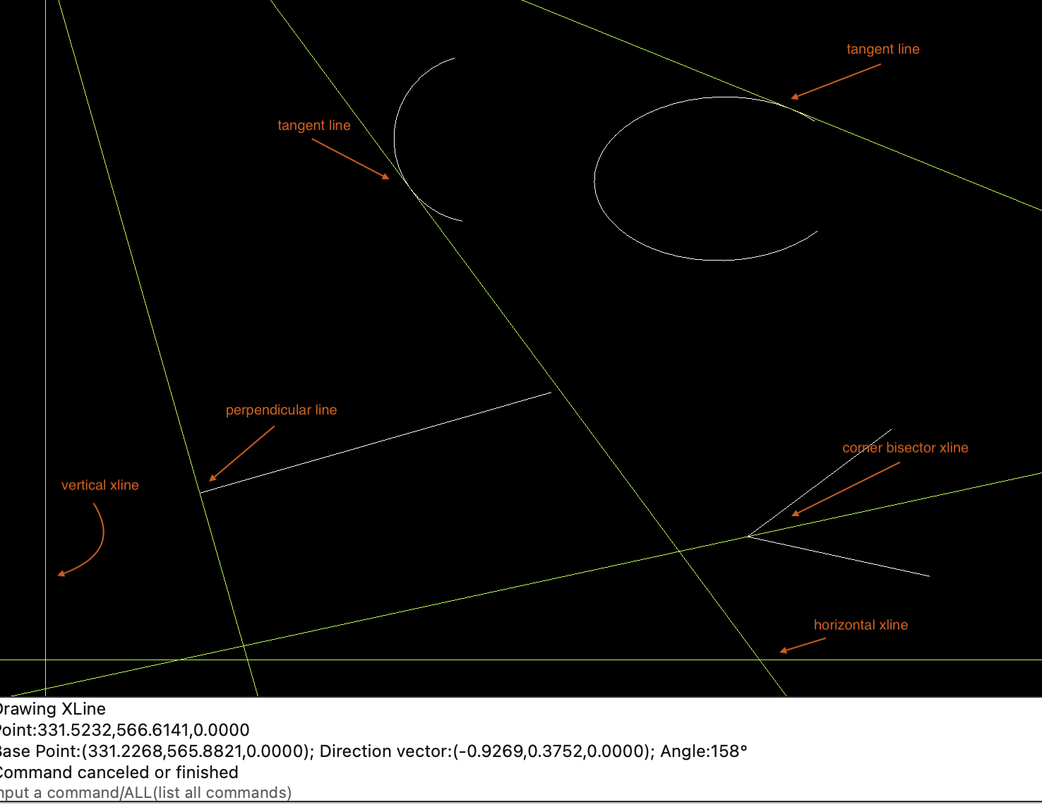
2.28 XL (Draw a Xline)
Draw a Xline
- Draw a xline through 2 points
- Draw a horizontal xline
- Draw a vertical xline
- Draw a xline perpendicular to a linear entity
- Draw a xline with a specified included angle
- Draw a corner bisector xline
- Draw a tangent line of an arc, circle or ellipse
- Draw a xline parallel to a linear entity
- Draw the common tangent of 2 circles
2.28.1 Draw a xline through 2 points
Specify 2 points on the xline to determine a xline
2.28.2 Draw a horizontal or vertical xline
When specifying the starting point of a xline, input 'H' to draw a xline parallel to the X axis, and input 'v' to draw a xline parallel to the Y axis.
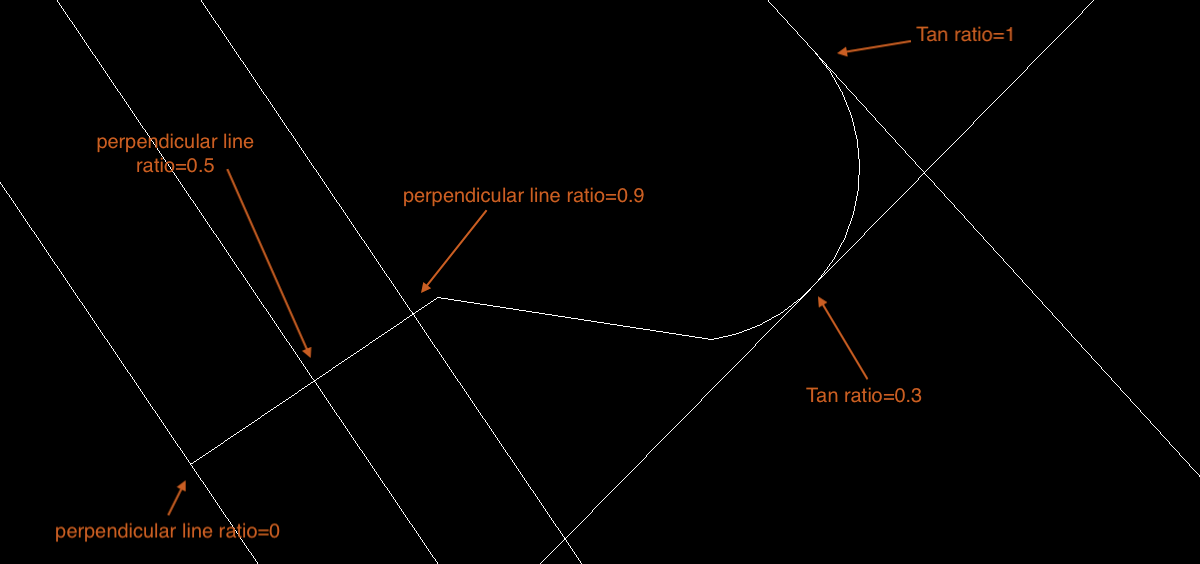
2.28.3 Draw a xline perpendicular to a linear entity
When specifying the starting point of a xline, input 'p' to draw a xline perpendicular to the specified a linear entity; If the specified curve is a line or polyline, you need to specify the insertion point or position ratio. For example, to add a perpendicular xline at the midpoint of a line, input 0.5 to insert a perpendicular xline at the midpoint of the line; 0 < = position ratio < = 1, 0 represents the start point of the curve, 1 represents the end point
2.28.4 Draw a xline with a specified included angle
When specifying the starting point, input 'a' to specify the angle, and draw the xline with the specified angle of the X axis. input 'r' to draw and specify the xline of the included angle of the linear entity; If the specified curve is a line or polyline, you need to specify the insertion point or position ratio. For example, to add an angle xline at the midpoint of a line, input 0.5 to insert an angle xline at the midpoint of the line; 0 < = position ratio < = 1, 0 represents the start point of the curve, 1 represents the end point
2.28.5 Draw a corner bisector xline
When specifying the starting point, input 'b' to draw the angular bisector; Specify the vertex, start point and end point of the angle, and draw the angle bisector; Or input 'r' to select 2 intersecting linear entities to draw angular bisectors
2.28.6 Draw a tangent line of an arc, circle or ellipse
When specifying the starting point, input 't' to draw the tangent line of arc, circle and ellipse; After specifying the curve, you need to specify the insertion point or position ratio. 0 < = position ratio < = 1, 0 represents the start point of the curve and 1 represents the end point
2.28.7 Draw a xline parallel to a linear entity
When specifying the starting point, input 'o'to draw a xline parallel to the specified linear entity
2.28.8 Draw common tangent

2.29 RAY (Drawing a ray)
Drawing a ray, the use of the command is similar to drawing xline; See 2.28
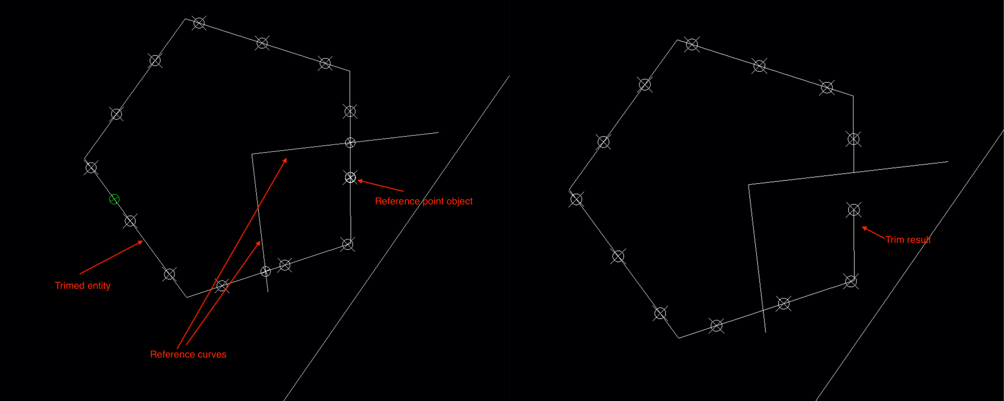
2.30 TR (Trim entities)
Trim entities. you could use this command to trim xlines, rays, lines, circles, arcs, ellipses, elliptical arcs, polylines, and 2D polylines.
- Select a entity to trim
- Specify a reference entity for the trimed entity. reference could be a curve or point object,The reference entity must intersect with the trimed entity
- Circles and ellipses can be trimed only if they have at least 2 reference points. xlines, rays, lines, arcs and elliptical arcs can be trimed only if they have 1 reference point
- There is no restriction on specifying multiple reference points for polylines and 2D polylines; If vertexs of the polyline are >= 3, you can trim without specifying a reference point
2.30.1 Select a entity to trim
The entity to be trimed is marked with a green dot. When the triming condition is reached, input 't' to start clipping the entity.
2.30.2 Select reference entity
The reference curve must intersect with the curve to be trimed. There is no limit on the number of reference curves for polylines and 2D polylines. Other curves can only specify 6 reference points at most; If the reference object is a point object, the point must be on the curve to be trimed (the reference point object must be selected by clicking).
2.30.3 trim entity
After specifying the reference point, input 't' to start triming the entity; Click the mouse at the position to be trimed to complete the triming function

2.31 O (Offset a curve)
Offset a curve, you could use this command to offset xlines, rays, lines, circles, arcs, ellipses, elliptical arcs, polylines, and 2D polylines.
- Offsets the curve to a specified point
- Offsets the curve to the specified position of the specified curve
- Offset the curve by the specified distance N times
- Set the layer of the new curve
2.31.1 Offsets a curve to a specified point
After selecting the curve to be offset, input 'T' to specify the offset point, and click the mouse to complete the offset.
2.31.2 Offsets the curve to the specified position of the specified curve
After selecting the curve to be offset, input 'T' and select the reference curve. Note: the reference curve must be a curve with a start point and an end point to specify the position. For example, to offset the curve to the center point of a curve, input 0.5; 0 < = ratio < = 1
2.31.3 Offset the curve by the specified distance N times
After selecting the curve to be offset, input the distance to be offset; The distance < 0 indicates that the curve extension point rotates 90 degrees clockwise, and the distance > 0 indicates that the curve extension point rotates 90 degrees counterclockwise; If it is a circle, arc or ellipse, the tangent of the starting point rotates ± 90 degrees.
After specifying the offset distance, input the number of times to offset N to complete the curve offset. 1 <= N <= 20
2.31.4 Set the layer of the new curve
Input 'L' to set the layer of the new curve, 'C' represents the current layer of the drawing, 'S' represents the same as the original curve layer

2.32 ERA (Erase the selected entity)
Erase the selected entity; You can erase a single entity or box select to erase multiple entities
2.33 ESC
Canceling the currently executing operation is the same as pressing the ESC key on the keyboard
2.34 U (Undo)
undo
2.35 RO (Rotate selected objects)
Rotate selected objects
- Rotate to specified angle
- Rotate objects by copied
- Rotate objects by Refence
2.35.1 Select objects to rotate and specify base point
Move mouse to select objects and then input 'B' to specify base point
2.35.2 Specify angle
Input angle value to rotate objects; Note: 0 < | angle | < 360
2.35.3 Rotate objects by copied
Input 'C' to rotate objects by copied; input copy number and angle to rotate objects
2.35.4 Rotate objects by Refence
Input 'R' to rotate objects by refence, specify 2 rotation points and 2 reference points, and the objects will rotate to the position where the line formed by the rotation points is parallel to the line formed by the reference points.
2.36 SC (Scale selected objects)
Scale selected objects
- Scale to specified value
- Scale objects by copied
- Scale objects by refence
2.36.1 Select objects to scale and specify base point
Move mouse to select objects and then input 'B' to specify base point
2.36.2 Specify scale value
Input scale value to scale objects; Note: value > 0
2.36.3 Scale objects by copied
Input 'C' to scale objects by copied
2.36.4 Scale objects by refence
Input 'R' to scale objects by refence
2.37 M (Move objects)
Move objects which be selected
- Move objects to specified position
- Move objects by copied
- Move objects by direction and distance
2.37.1 Select objects to move and specify base point
Move mouse to select objects and then input 'B' to specify base point
2.37.2 Move objects to specified position
2.37.3 Move objects by copied
Input 'C' to move objects by copied
2.37.4 Move objects by direction and distance
Input 'D' to specify direction and then input distance to move objects. Note: distance > 0
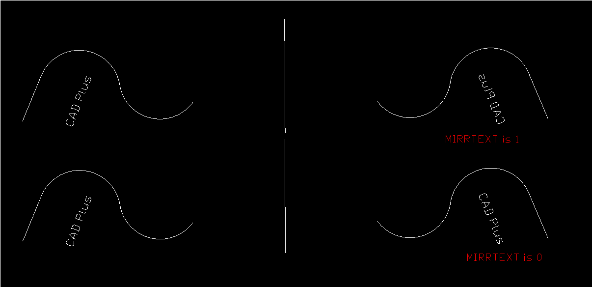
2.38 MI (Mirror objects)
Mirror objects which be selected
2.38.1 Select objects to mirror
Move mouse to select objects and then input 'P' to specify refence points or refence object
2.38.2 Specify refence points or refence object
Specify 2 points or select a linear object as the reference object to finish mirroring
2.39 DIV (Divide)
divide a curve or distance between 2 points. Note: the curve must has start point and end point
If select a polyline, before specifying the number of segments, input 'C' to divide only the selected segment, and input 'A' to divide the whole polyline

If the points are not displayed normally, change the point style to display the points normally

2.40 JOIN
Merge multiple end to end curves into a single polyline
- Merge arcs, segments, polylines into one polyline
- Convert an arc to a circle; polyline arcs with only 2 vertices are converted to a circle; convert an elliptical arc to an ellipse
2.41 ATT (Add attribute definition)
Add an attribute definition
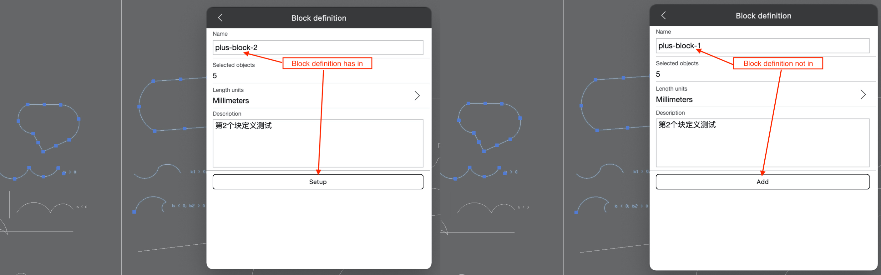
2.42 B (Create a block definition)
Create a block definition, select objects then input 'C' to create a block definition. Note:If the inputed block definition name already exists, it means to modify the block definition; if the name does not exist, it means to add a new block definition.
2.43 I (Insert block reference)
Insert block reference
- Select a block definition which to be inserted
- Input 'S' to set up scale of block reference, Note: scale > 0
- Input 'A' to set up rotation angle
- Input 'AT' to set up attribute of block
2.44 EX (Explode objects)
Explode objects, This command can explode block references or polylines; If you want to modify a block definition, you can use this command to explode the corresponding block reference and recreate the block definition with the same name.
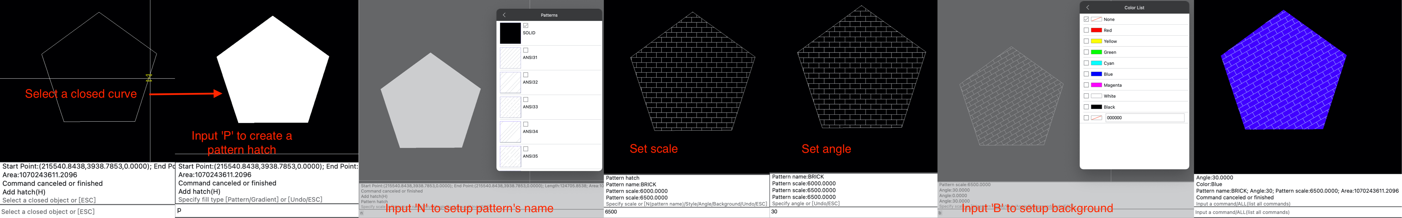
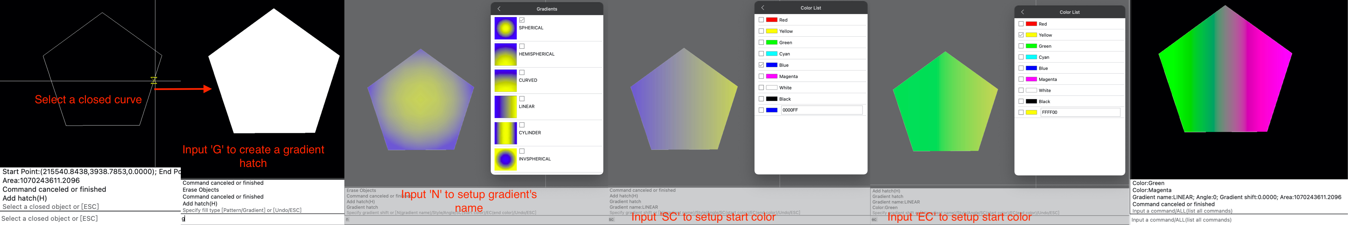
2.45 H (Add hatch)
Add a pattern hatch or gradient hatch; you can add a hatch for a closed planar curve or a region.
2.45.1 Select a closed planar curve or a region
The curve must is closed and planar
2.45.2 Specify hatch type
Input 'P' is a pattern hatch, 'G' is a gradient hatch
2.45.2.1 Set params of a pattern hatch
2.45.2.2 Set params of a gradient hatch
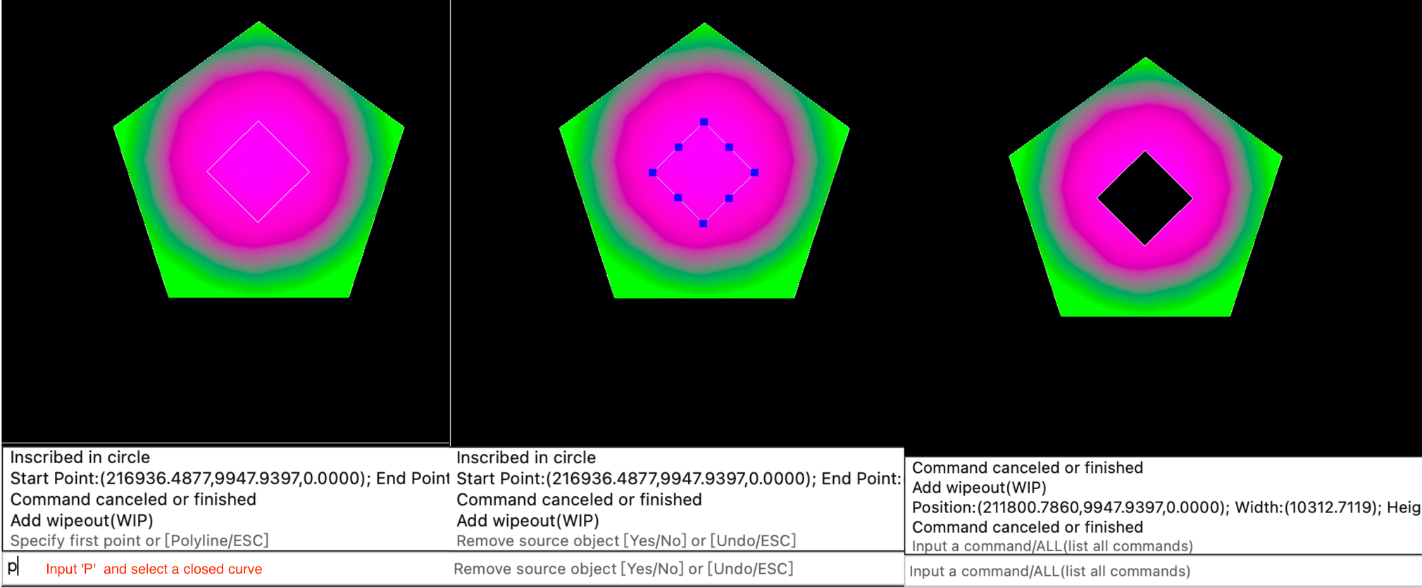
2.46 WIP (Add a wipeout)
Add a wipeout
- Add a wipeout by vertexs (vertexs' number >= 3)
- Add a wipeout by a linar closed polyline
2.46.1 Add a wipeout by vertexs

2.46.2 Add a wipeout by a linar closed polyline
2.47 DO (Add a donut)
Add a donut
Specify inner diameter/radius and outer diameter/radius to draw a donut, inner diameter/radius >= 0, outer diameter/radius >= inner diameter/radius
2.48 EXT (Extend curves)
Extend curves, support to extend line, ray, xline, arc, elliptical arc, mline, polyline, 2D polyline
2.48.1 Select reference object
The reference object must be line, ray, xline, polyline, 2D polyline, arc, circle, ellipse, elliptical arc.
2.48.2 Select objects to be extended
Objects to be extended could be line, ray, arc, elliptical arc, polyline, 2D polyline, mline.

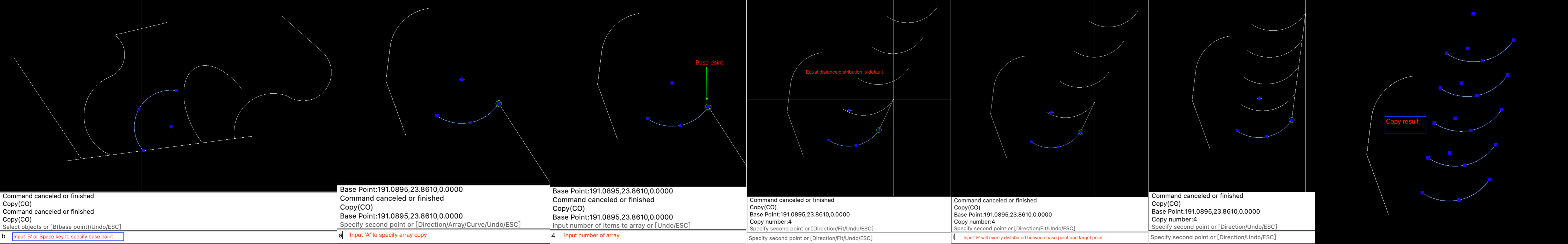
2.49 CO (Copy objects)
Copy objects
- Copy objects to specified position
- Copy objects by direction and distance
- Copy objects by array
- Copy objects on a curve
2.49.1 Select objects to copy
Click the mouse to select a single object or box select multiple objects to copy
2.49.2 Specify base point
Input 'B' or space key to specify the base point
2.49.3 Specify target point
Move the mouse to the position to be copied and click the mouse to finish copying

2.49.4 Copy objects by direction and distance
When specifying the target point, input 'D' to specify the direction to copy, and then input the distance or click the mouse in the drawing to complete the copy. distance > 0

2.49.5 Copy objects by array
When specifying the target point, input 'A' to start array copying. Array copy can copy multiple copies of objects at the same time. By default, copies of objects are distributed equidistant from the base point to the target point. input 'F' will distribute the copies evenly between the base point and the target point.
2.49.6 Copy objects on a curve
When specifying the target point, input 'C' to select a curve, and the object will be copied along the curve; Note: The selected reference curve must have start point and an end point. input 'E' and then input the distance to copy on the curve according to the specified distance, input 'DI' and input the number of equal divisions N to divide the curve into N segments, and N+1 copies will be copied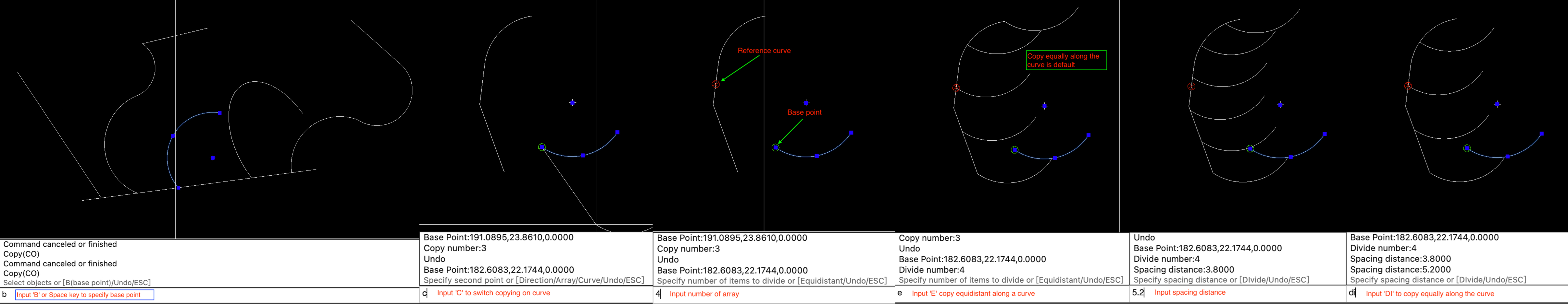
2.50 F (Fillet curves)
Fillet selected curves, support filleting xline, ray, line, arc, polyline, 2D polyline.
2.50.1 Specify radius
Input radius to fillet, radius >= 0. Note:If two lines are parallel, specify radius of 0 directly. The fillet of parallel lines cannot be trimed
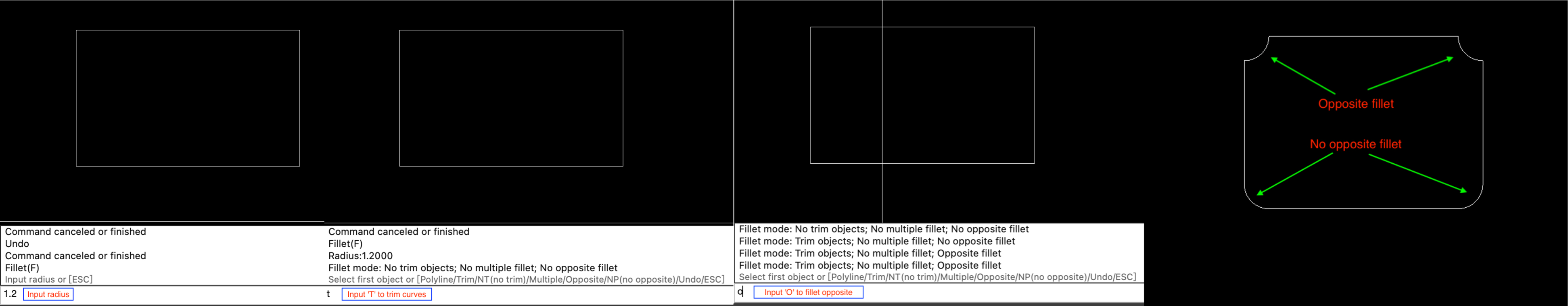
2.50.2 Select objects to fillet
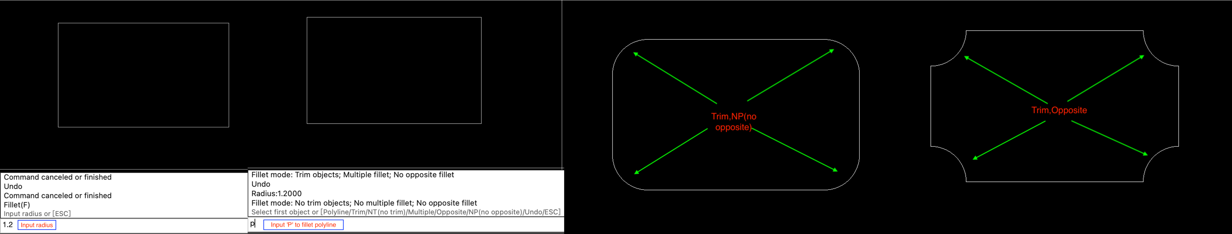
Select 2 curves or 2 segments of a polyline to fillet (only 2 segments of the same polyline can be filleted). Enter 'T' to trim on the 2 curves to be filleted, and 'NT' will not trim the curves to be filleted; 'M' perform multiple filleting operations; 'O' generate reverse fillet arc; 'NP' generate positive fillet arc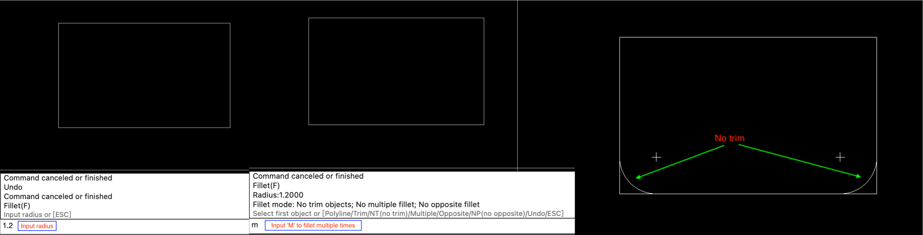
2.50.3 Fillet object for polyline or 2D polyline
After input radius, enter 'P' to select a polyline or 2D polyline to fillet
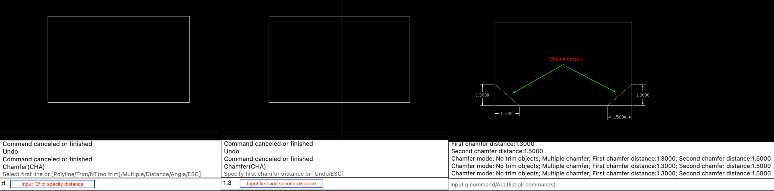
2.51 CHA (Chamfer curves)
Chamfer the selected curves. Chamfer xline, ray, line, polyline, 2D polyline are supported. Cannot chamfer 2 parallel lines
- Specify the distance of the first and second edges to chamfer
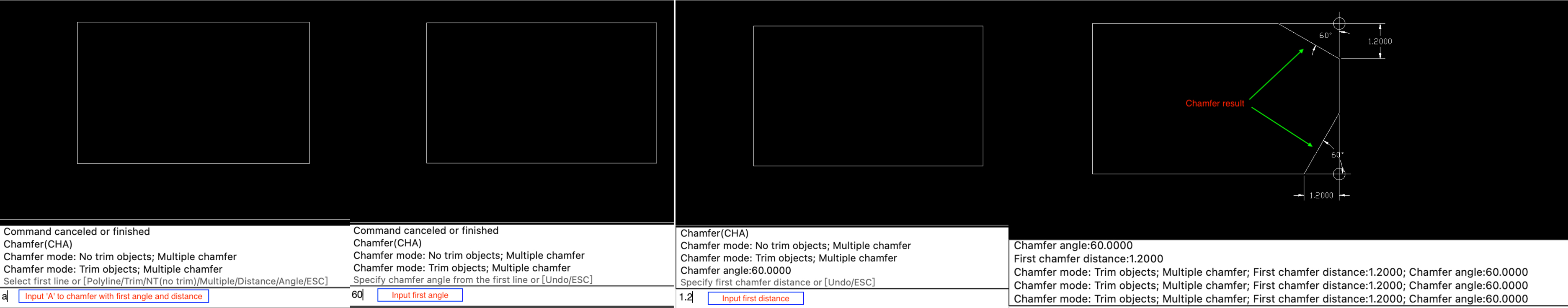
- Specify the angle of the first edge, and the first edge to chamfer
2.51.1 Select 2 lines to chamfer
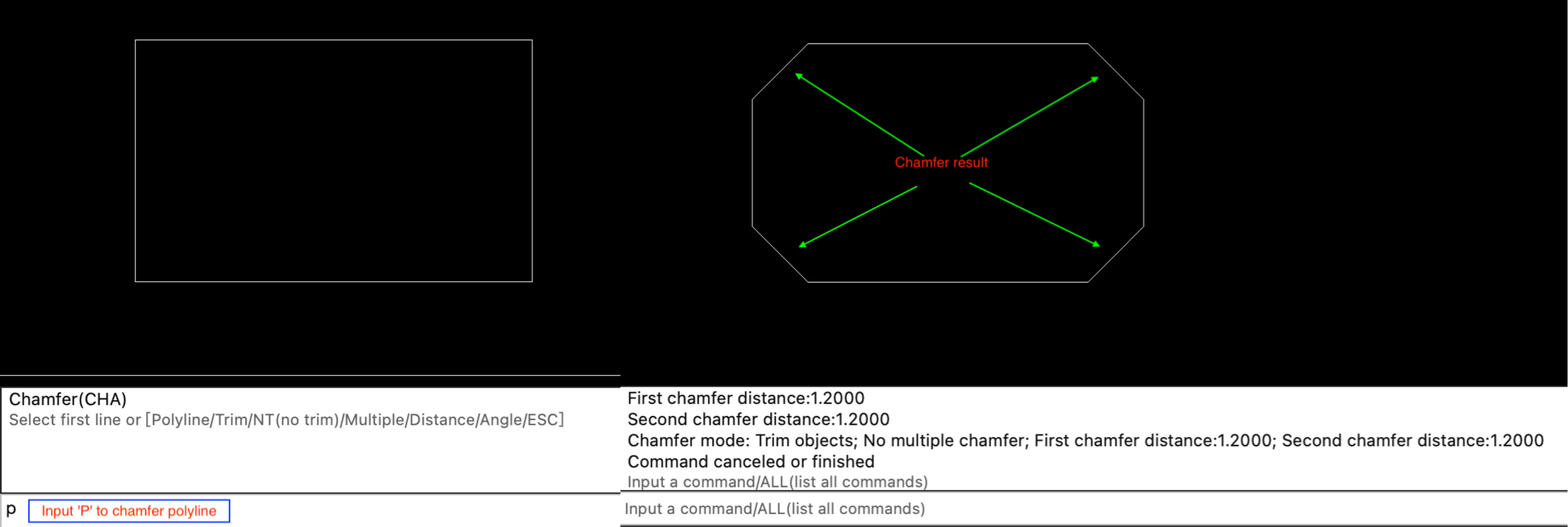
Select 2 curves or 2 segments of a polyline to chamfer (only 2 segments of the same polyline can be chamfered). Enter 'T' to trim on the 2 curves to be chamfered, and 'NT' will not trim the curves to be chamfered; 'M' perform multiple chamfering operations; 'D' specify the distance between 2 lines;'A' specify the angle of the first line
2.51.2 Chamfer according to the distance of 2 edges
Input the chamfer distance of 2 edges. The distance must be>=0
2.51.3 According to the angle and distance of the first side to chamfer
Input the angle and distance of the first edge to chamfer
2.51.4 Chamfer polyline
2.52 R (Redo)
redo
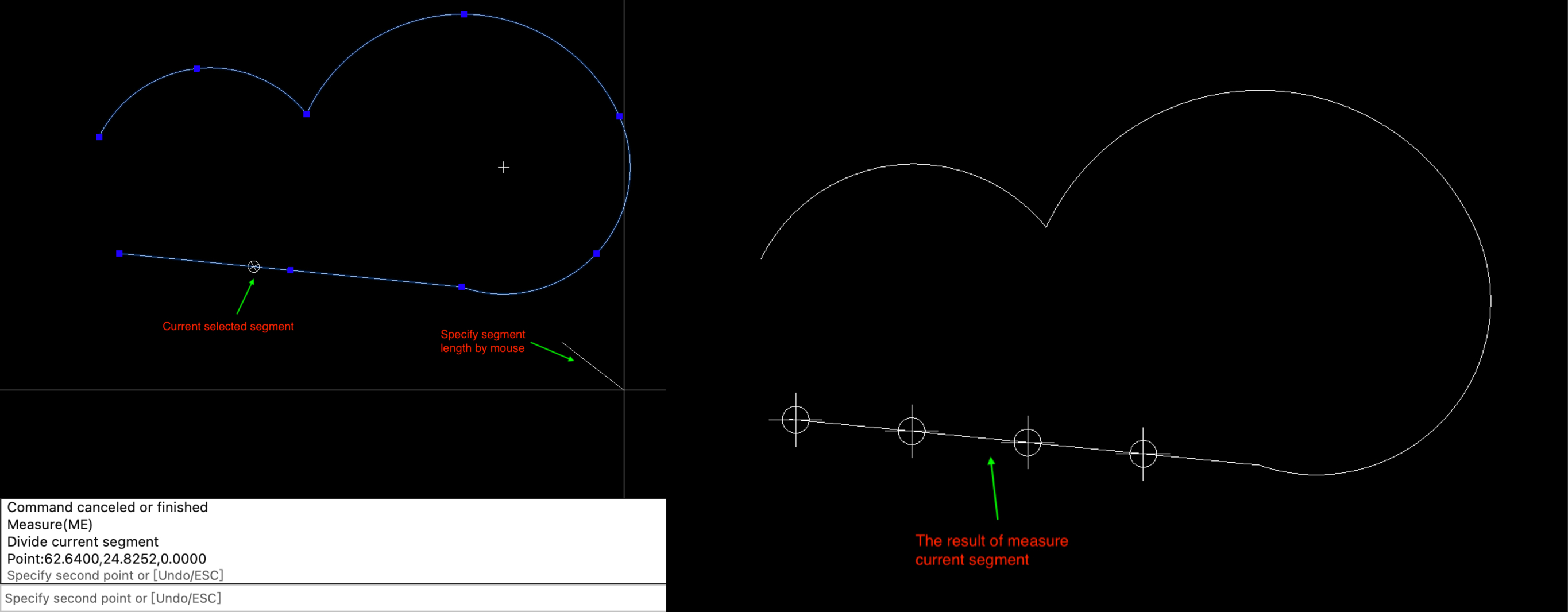
2.53 ME (Measure curve)
Measure the selected curve equally by distance
2.53.1 Select a curve
The selected curve must has start point and end point. could not measure xline and ray.
2.53.2 Specify distance
Input the equal distance or specify 2 points in the drawing by mouse to determine the equal distance; If you select a polyline before the specified distance, input 'C' to measure only the selected segment, or input 'A' to measure the entire polyline. By default, all segments are equally measured. If points cannot be displayed correctly, please refer to 2.39 DIV command.the distance > 0

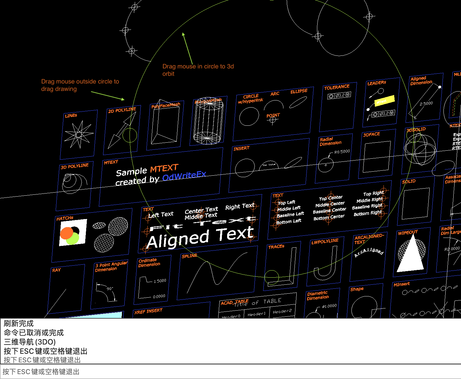
2.54 3DO (3D orbit)
3D orbit. this command only run in model space.
Use this command to view 3D drawings. Drag the mouse inside the circle to perform 3D conversion, or drag the mouse outside the circle to drag the drawing
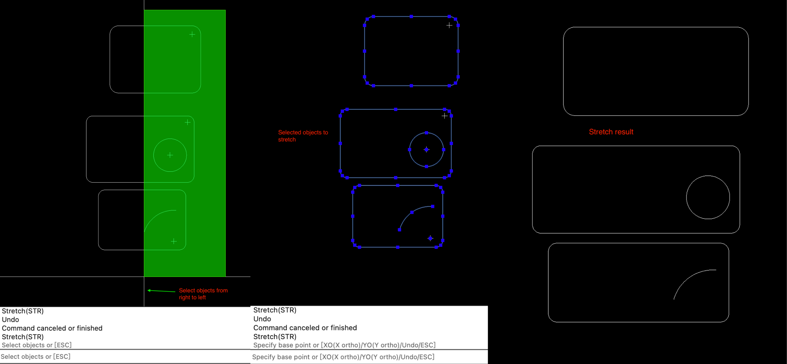
2.55 STR (Stretch objects)
Stretch selected objects
2.55.1 Select objects
When selecting objects, you must select them from right to left, or you cannot stretch them
2.55.2 Specify base point or Stretching method
Input 'XO' to stretch the selected objects along the X axis, and Input 'YO' to stretch the selected objects along the Y axis.
2.56 BR (Break curves)
Break selected curves
2.56.1 Select a curve to break
Support breaking xline, ray, line, arc, circle, polyline, 2D polyline, elliptical arc, and ellipse.
2.56.2 Specify the second break point or offset distance
When inputting distance, if the distance=0, the first point and the second point coincide; if the distance>0, the second point is behind the first point along the curve direction; if the distance<0, the second point is in front of the first point along the curve direction. If the broken curve is a circle, an ellipse, or a closed polyline, the first and second points cannot coincide.

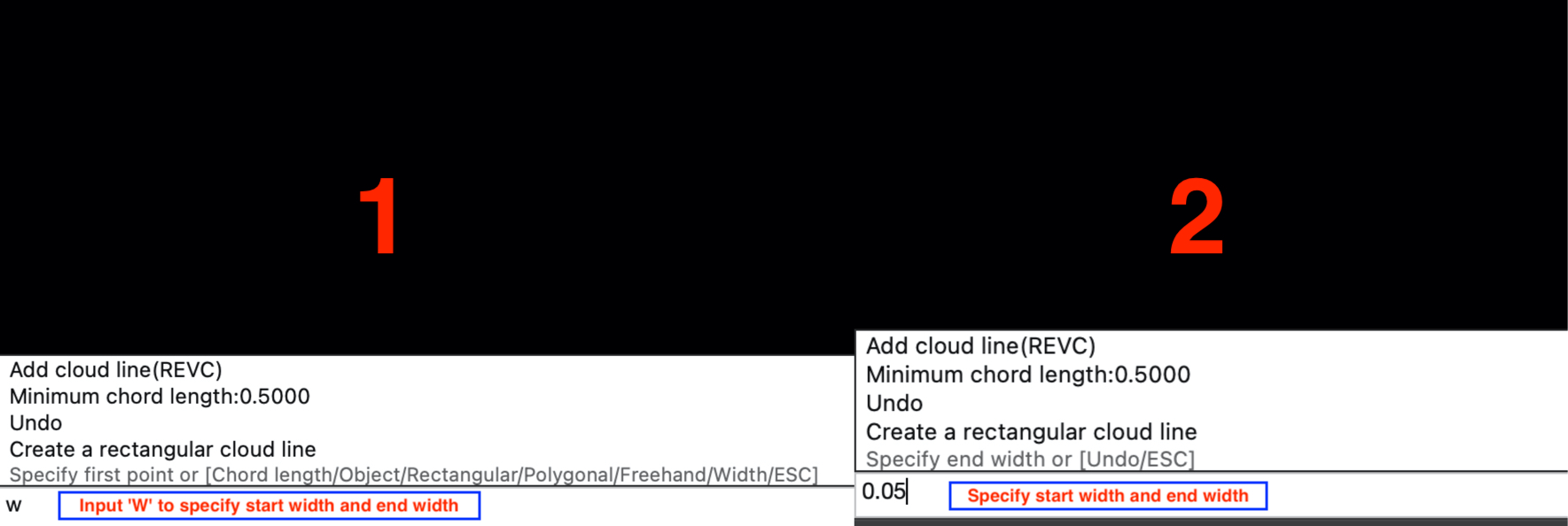
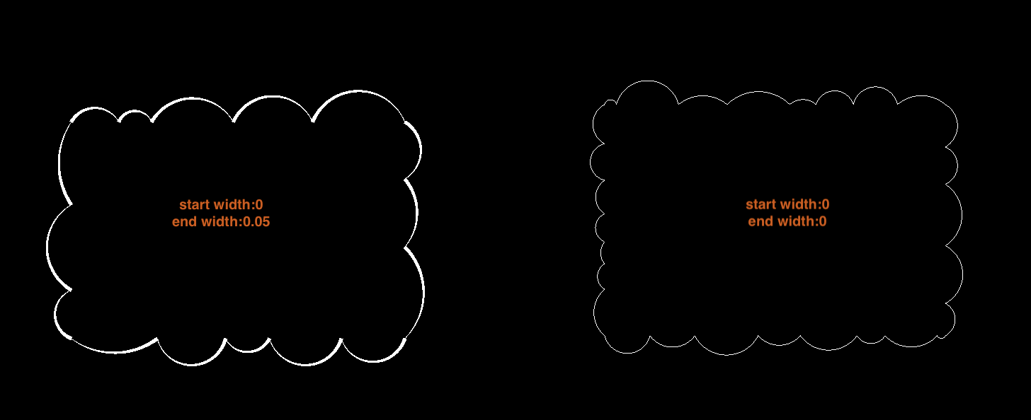
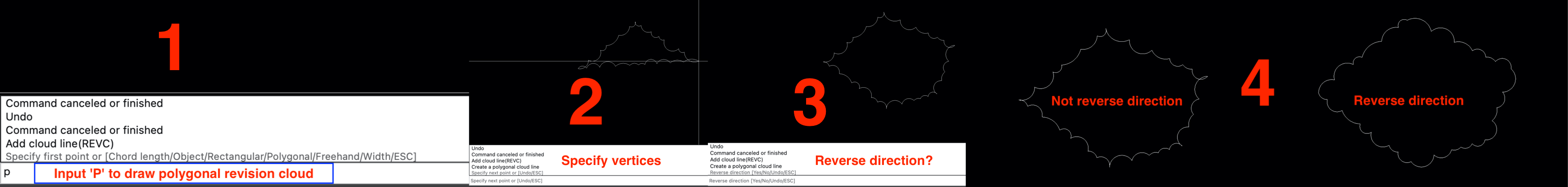
2.57 REVC (Draw Revision Cloud)
Draw a revision cloud. input 'C' to specify minimum chord length and maximum chord length(Note:maximum chord length <= 3*minimum chord length); input 'W' to specify start width and end width of segment.
- Draw a rectangular revision cloud
- Draw a polygonal revision cloud
- Draw a freehand revision cloud
- Create a revision cloud by object
2.57.1 Draw a rectangular revision cloud
The default is to draw a rectangular revision cloud, or input 'R' to draw a rectangular revision cloud; Specify the first point of the rectangular cloud, and move the mouse to determine the diagonal point of the cloud

2.57.2 Draw a polygonal revision cloud
Input 'P' to start drawing polygonal clouds. Polygonal clouds require at least 3 vertices. After determining the vertices, you can set the direction of the cloud arc or press the spacebar to complete the drawing directly.
2.57.3 Draw a freehand revision cloud
Input 'F' to start freely drawing the cloud. to complete the drawing, press the spacebar to complete the drawing, and you can also set the direction of the arc for hand drawn clouds.

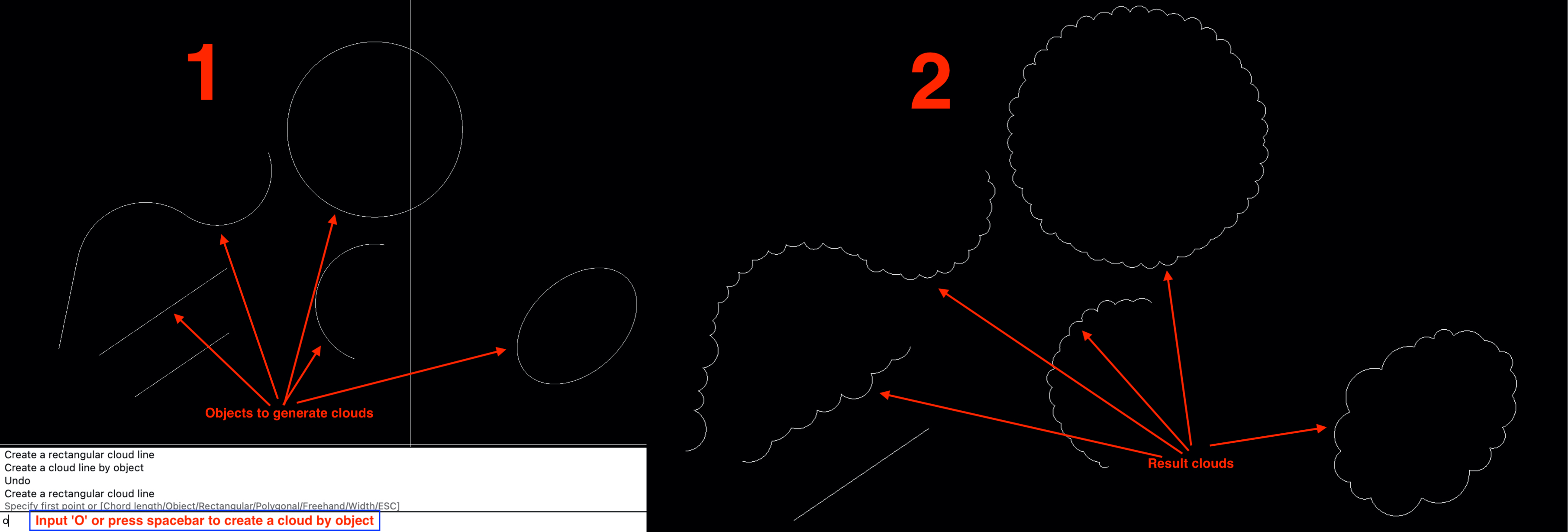
2.57.4 Create a revision cloud by object
Input 'O' or press the spacebar, and then select a curve to convert it to a cloud; supported curves include: lines, arcs, circles, elliptical arcs, polylines, and 2d polylines
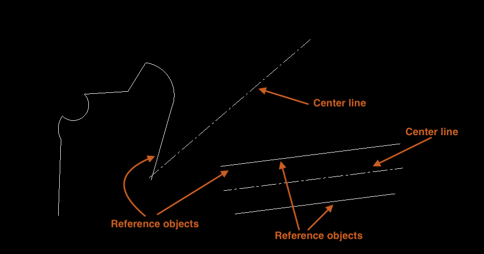
2.58 CL (Add center line)
Add a centerline to 2 line segments or the line segment of polylines
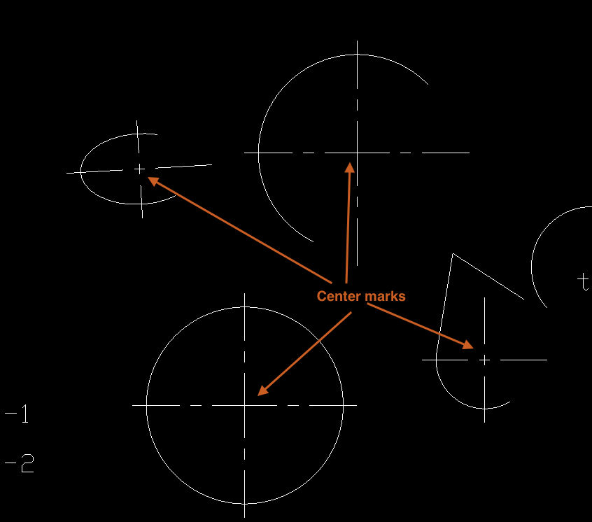
2.59 CM (Add center mark)
Add center marks for circles, arcs, elliptical arcs, or arc segments of polyline
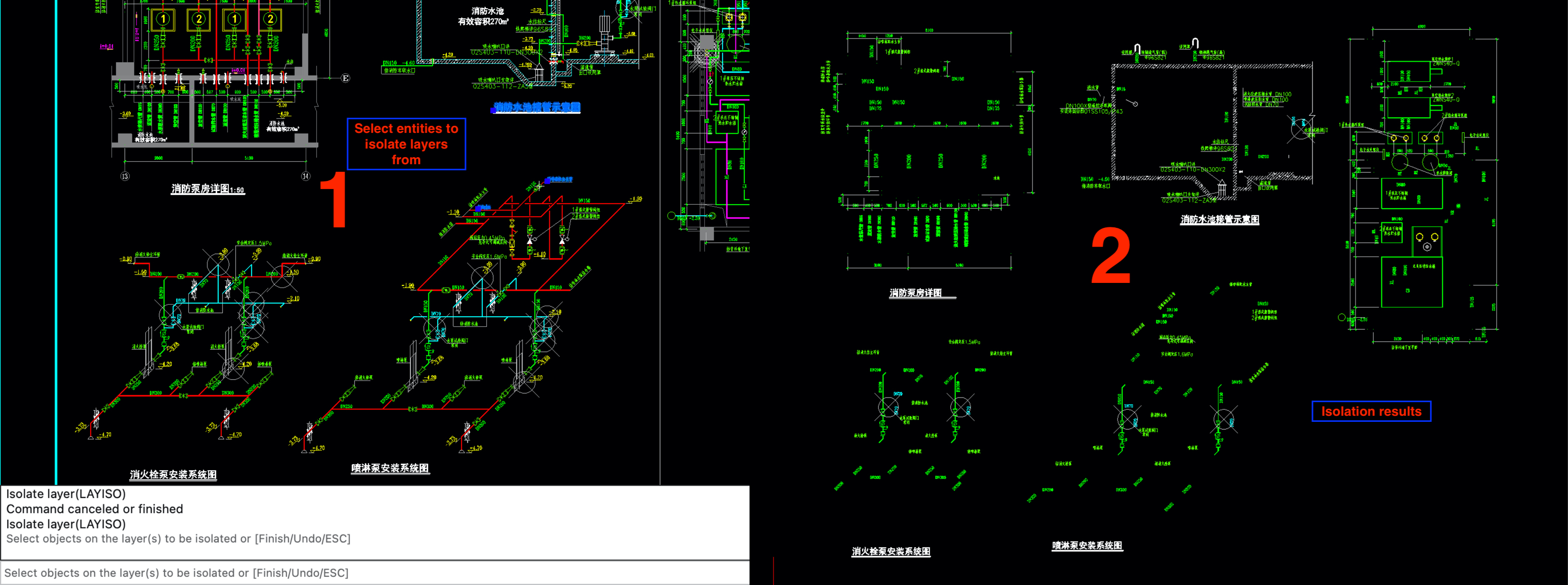
2.60 LAYISO (Isolate layers)
Isolate layers with the selected entities, and then input 'F' or press the spacebar to complete the layer isolation operation
2.61 LAYON (Turn on all layers)
Open all layers, and after executing the LAYISO command, some layers will be closed. Use this command to open those closed layers.
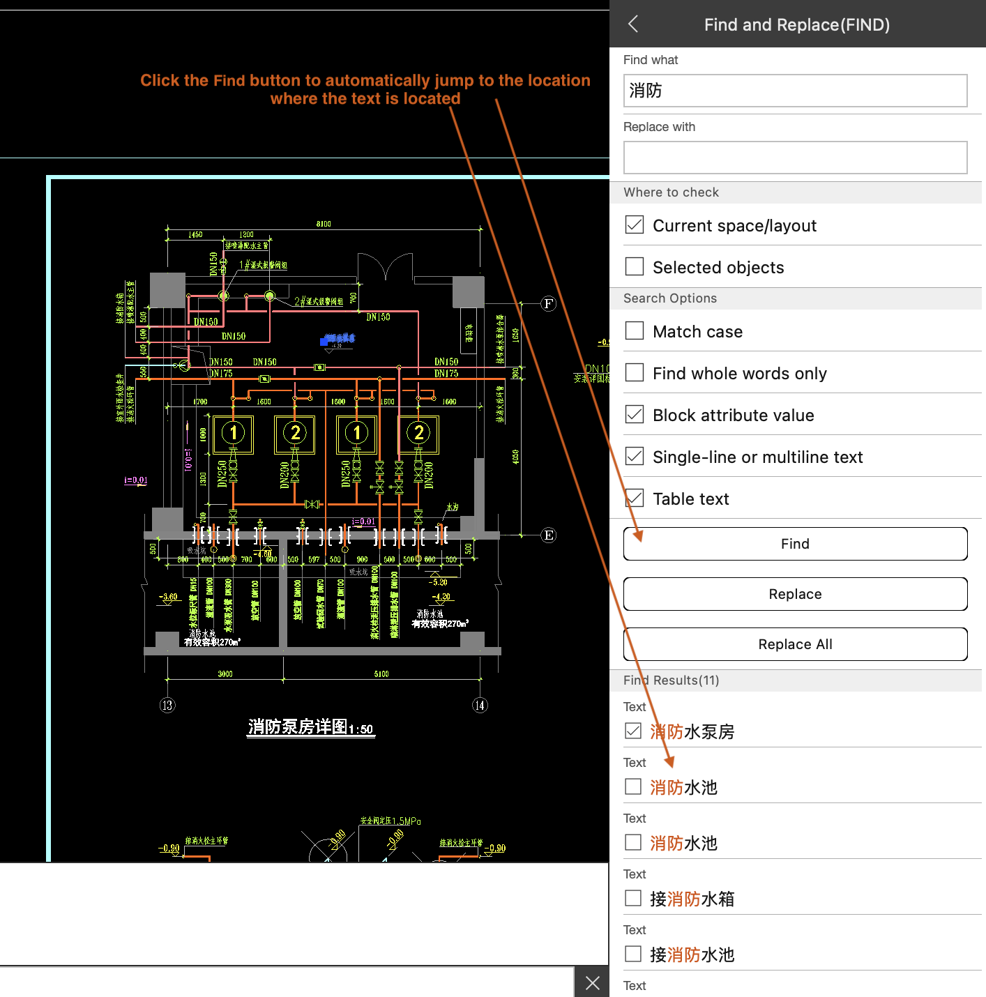
2.62 FIND (Find and replace text)
- Find and replace texts in the current layout
- Find and replace texts in the selected entities
2.62.1 Set search options
- Match case: Select this option to match the case of letters during search
- Find whole words only: Select this option to only be found when searching for exactly the same content as the search
- Block attribute value: Selecting this option will search for attribute values in the block reference when searching
- Single-line or multiline text: Selecting this option will search for single and multiple lines of text when searching
- Table text: Selecting this option will search for the text content in the table when searching
2.62.2 Find and replace texts in the current layout
Open the layout space you want to search for and input the content you want to search for. When the input is complete, press the Enter key to confirm that the text has been entered; Then click the Find button to search. Clicking on a search result will automatically locate the location of the text
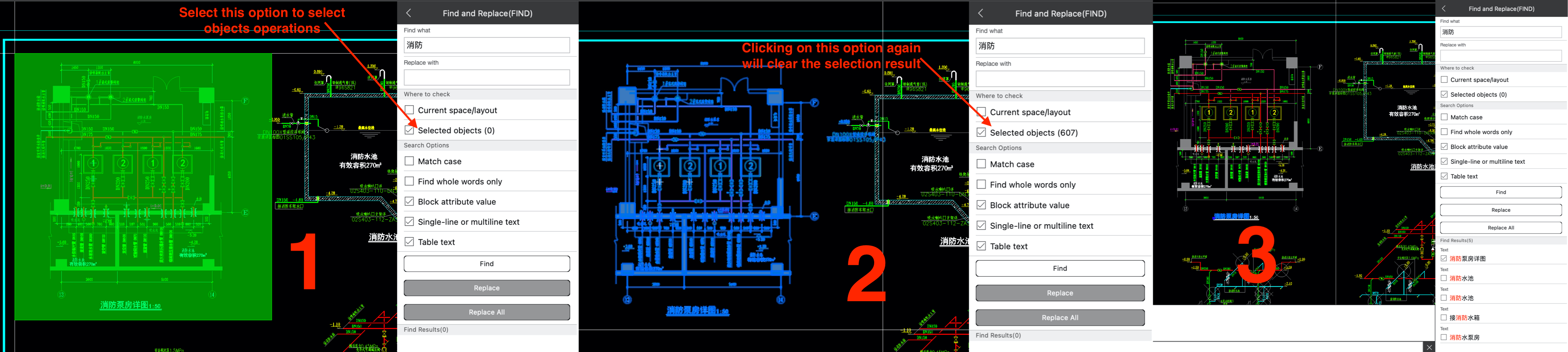
2.62.3 Find and replace texts in the selected entities
After input the content to search for, select the "Select Objects" option; Select the range you want to search in the drawing. Click the Find button to start searching. Objects selection can only be made in the drawing window when the "Select Objects" option is selected. If you want to clear the selected objects, you can click the "Select Objects" option again.
2.63 AS (Auto Save)
This command is only valid for subscription users
- Set save interval
- Turn off automatic saving
2.63.1 Set save interval
Save Unit of time as minute; The minimum time is 2 minutes, and the maximum time interval is 60 minutes.
2.63.2 Turn off automatic saving
Input 'O' to turn off automatic saving
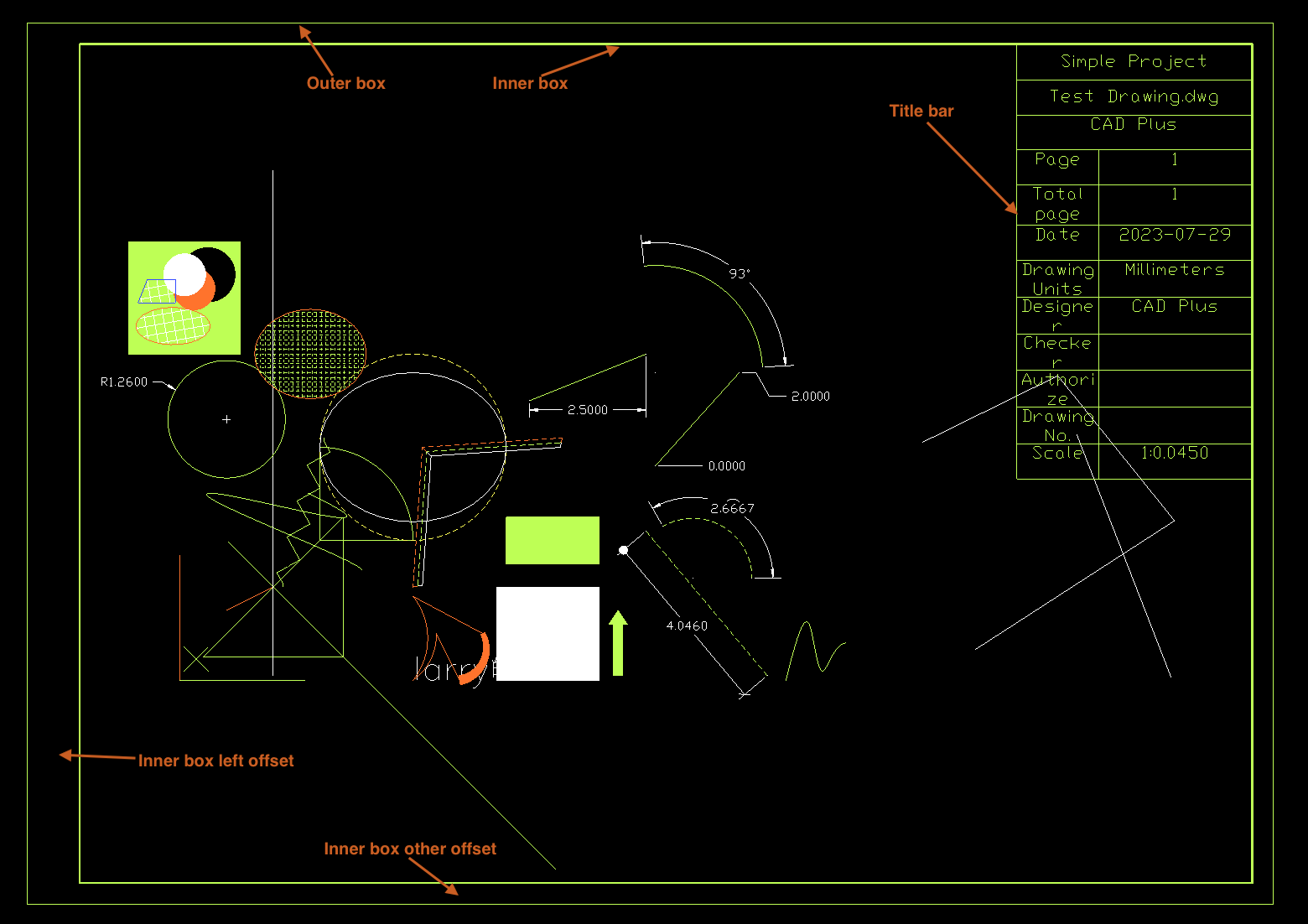
2.64 TK (Add Border)
- Set properties of the border
- Specify position of the border
2.64.1 Set properties of the border
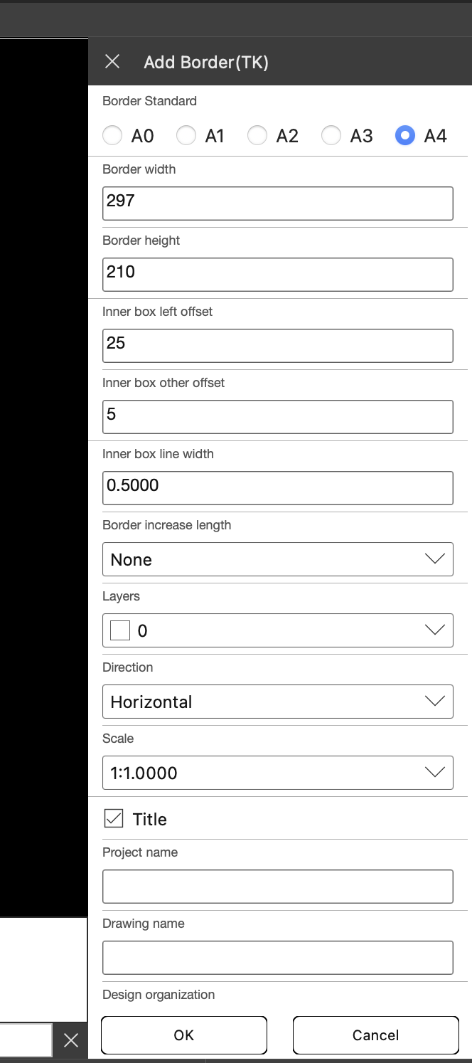
2.64.1.1 Set Border Standard
Set the Paper size of the border
A4: 210 * 297; A3: 297 * 420; A2: 420 * 594; A1: 594 * 841; A0: 841 * 1189
2.64.1.2 Set width and height of the border
Customize the Paper size of the border
2.64.1.3 Set inner box offset of the border
Set the left offset of the inner border and other offsets
2.64.1.4 Set Border increase length
The width extension value of the border
A4 + 1/8 = 210 * 334; A4 + 1/4 = 210 * 371; A4 + 1/2 = 210 * 446; A4 + 1 = 210 * 594
A3 + 1/8 = 297 * 473; A3 + 1/4 = 297 * 525; A3 + 1/2 = 297 * 630; A3 + 1 = 297 * 840
A2 + 1/8 = 420 * 668; A2 + 1/4 = 420 * 743; A2 + 1/2 = 420 * 891; A2 + 1 = 420 * 1188
A1 + 1/8 = 594 * 946; A1 + 1/4 = 594 * 1051; A1 + 1/2 = 594 * 1262; A1 + 1 = 594 * 1682
A0 + 1/8 = 841 * 1337; A0 + 1/4 = 841 * 1486; A0 + 1/2 = 841 * 1784; A0 + 1 = 841 * 2378
2.64.1.5 Set layer of the border
Select the layer where the border is located
2.64.1.6 Set direction of the border
Set the direction of the border, horizontal or vertical
2.64.1.7 Set scale of the border
set scale value of the border
2.64.1.8 Set title bar of the border
2.64.2 Specify position of the border
Move the mouse to the position you want to insert and click to complete the addition of the border
3. Functions description
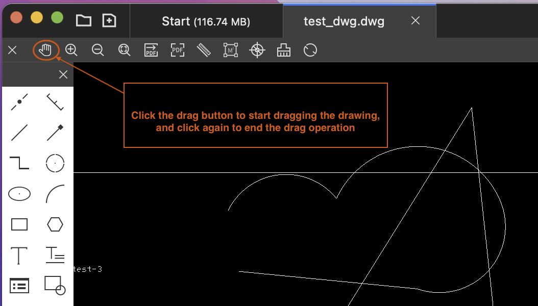
3.1 Drag Drawing
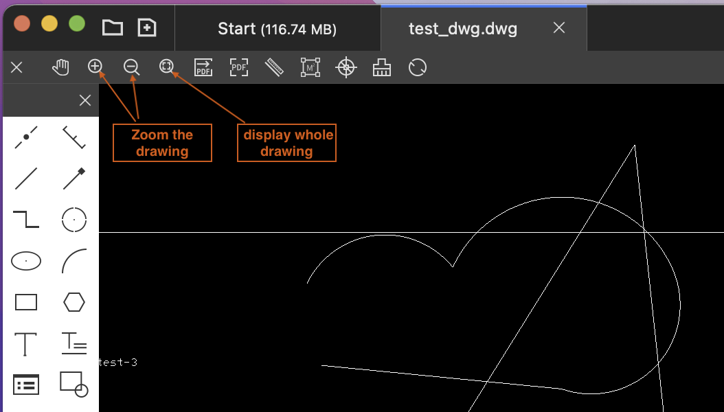
3.2 Scale Drawing
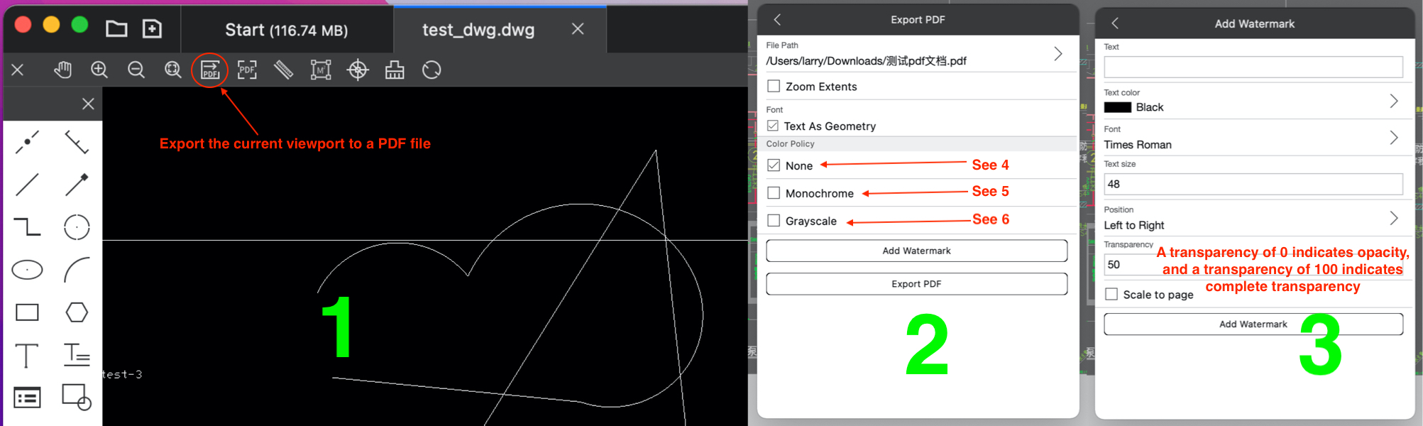
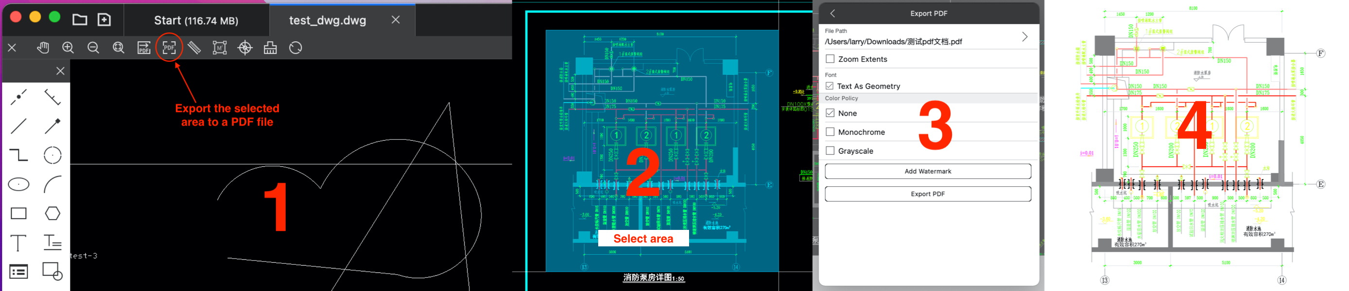
3.3 Export to PDF
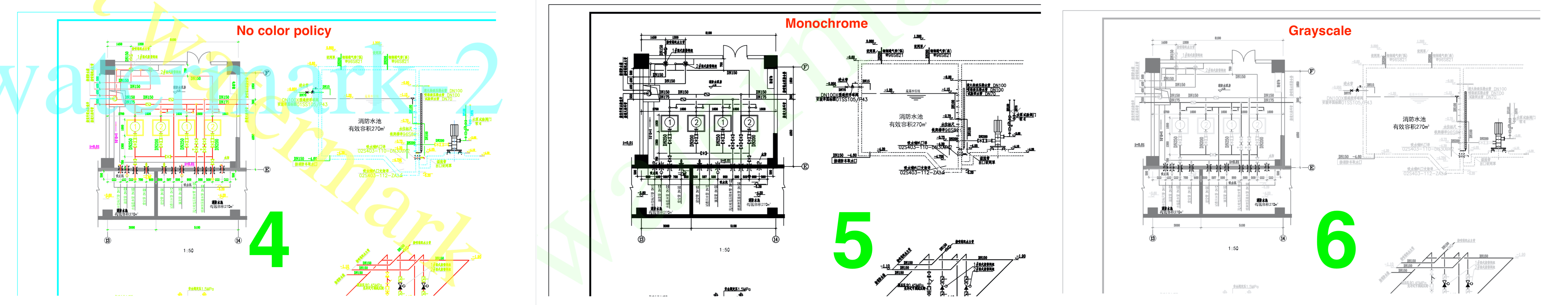
There are two ways to export to PDF, where you can add watermark text when exporting PDF (watermark text currently only supports English); The transparency value of the watermark is 0<=transparency<=100, transparency=0 indicates opacity, and transparency=100 indicates complete transparency
- Export the current viewport to a PDF file
- Export the selected area to a PDF file
3.3.1 Export the current viewport to a PDF file
3.3.2 Export the selected area to a PDF file
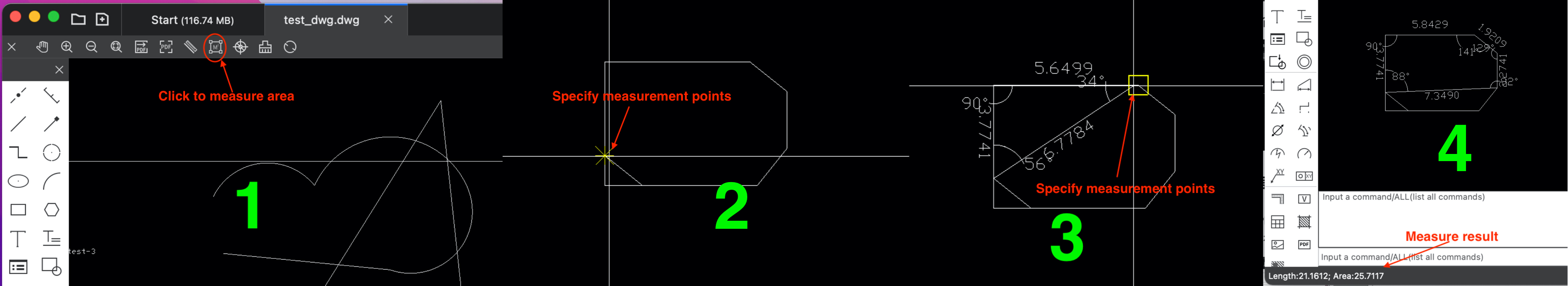
3.4 Measure distance, area
3.4.1 Measure distance
Measure the distance between specified 2 points

3.4.2 Measure area
Measure the area of more than 3 specified points, and press Enter to complete the measurement
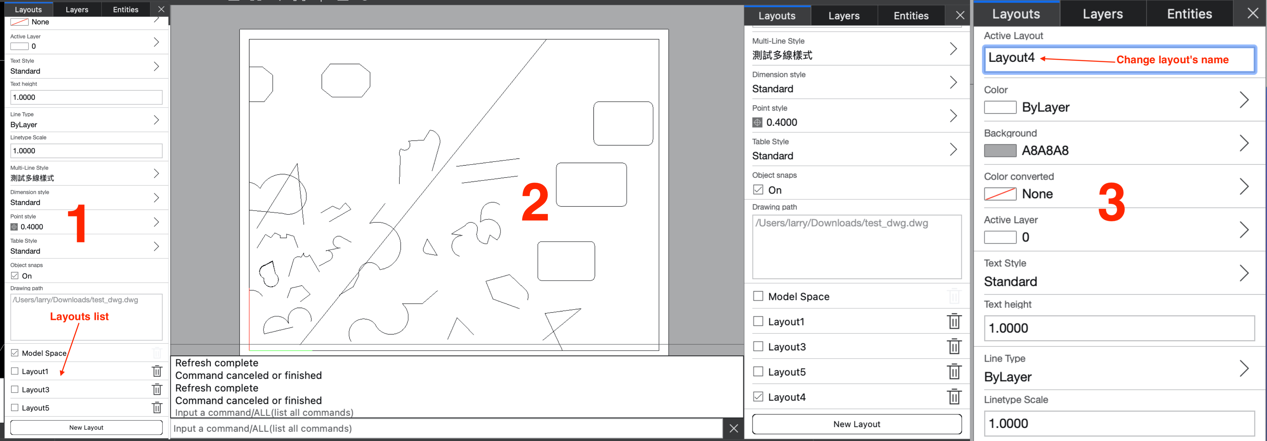
3.5 Layout Management
Using CAD Plus, you can add a layout to a drawing, change the name of the layout (model layout cannot change the name), set the active layout, and delete the layout; When the objects in the drawing do not display properly after switching layouts, you can input "RE" in the command to refresh the drawing.
3.6 Change color
Sets the current color of the drawing, which will be used by default for objects added to the drawing

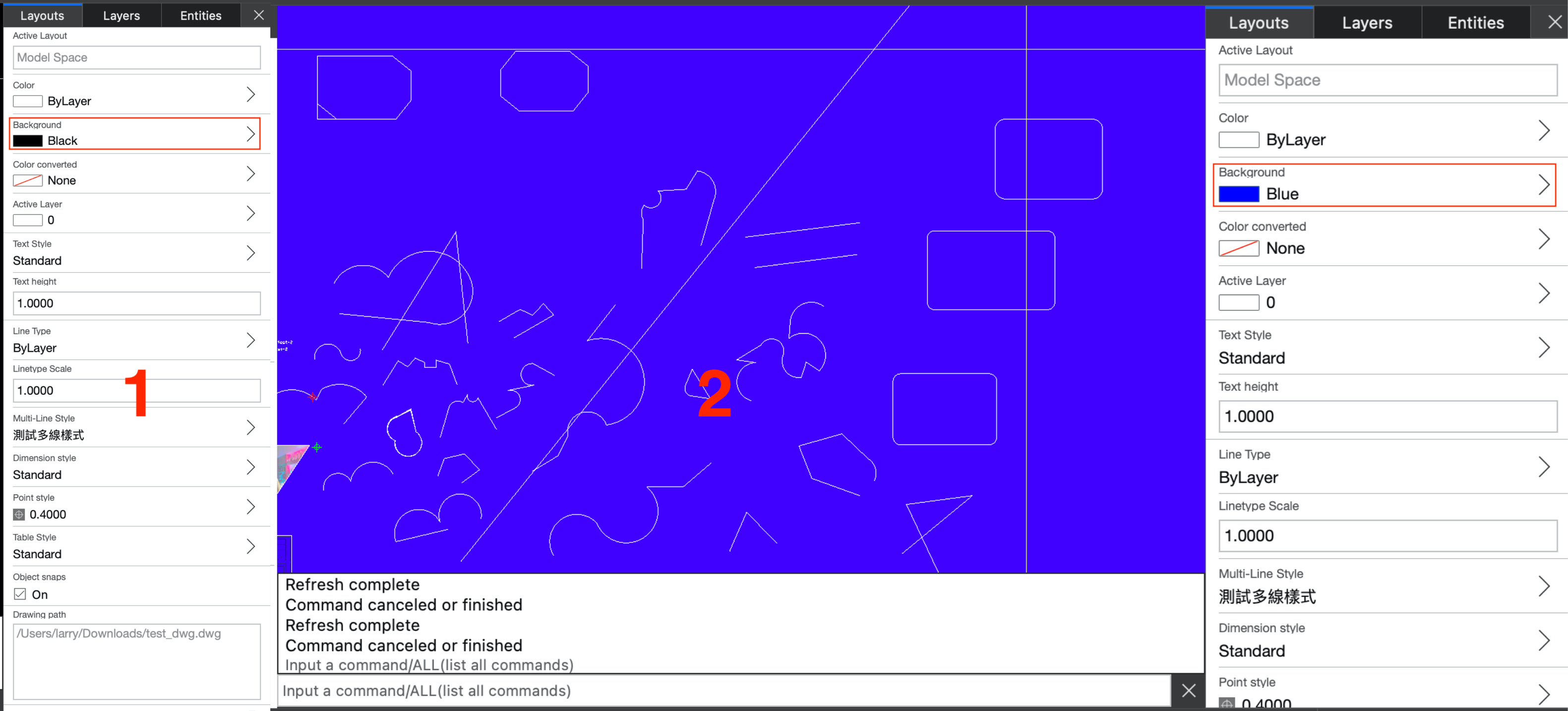
3.7 Change background color
3.8 Change Active Layer
Set the active layer, and subsequent objects added to the drawing will be added to this layer by default

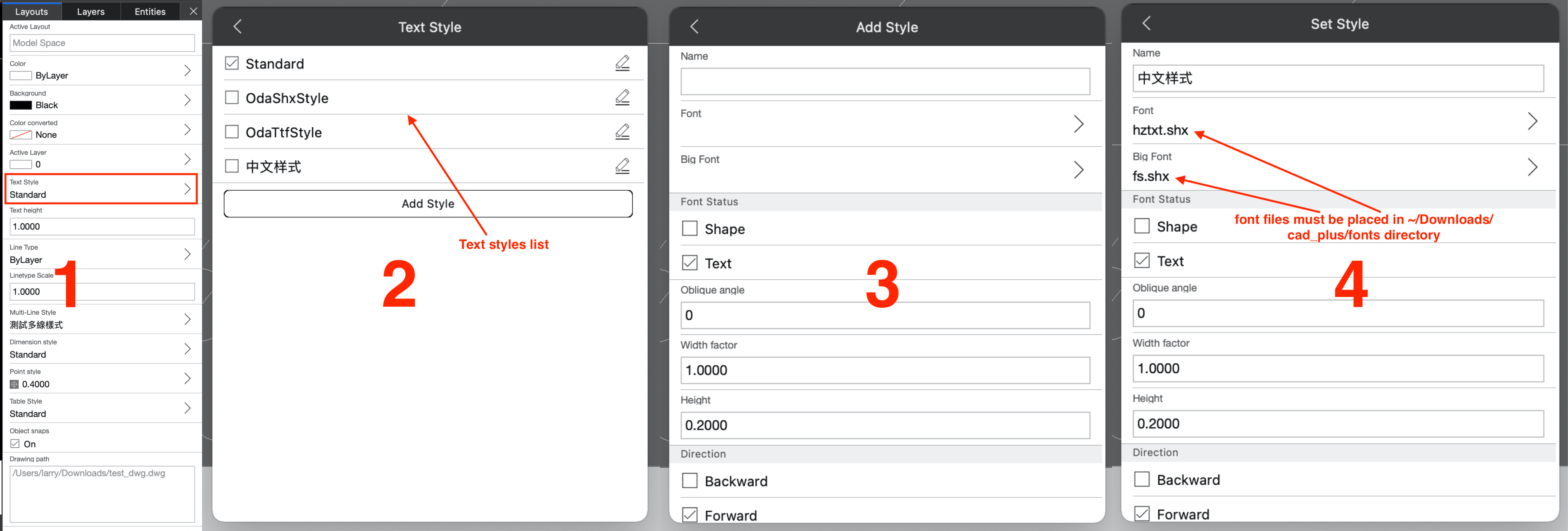
3.9 Manage Text style
You can add, delete, and modify text styles; If a text object in the drawing does not display properly (usually displayed as a question mark), you can use this function to correct the display of the text correctly. Note: In order for CAD Plus to correctly recognize fonts, font files must be placed in ~/Downloads/cad_plus/fonts directory
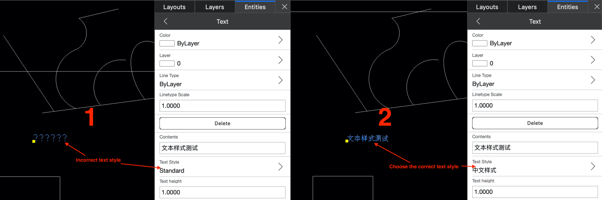
When a text object in the drawing does not display properly, you can change text style to correct the problem
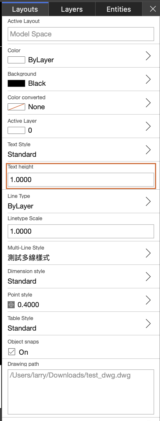
3.10 Change text height
This value will be used by default for text height added later
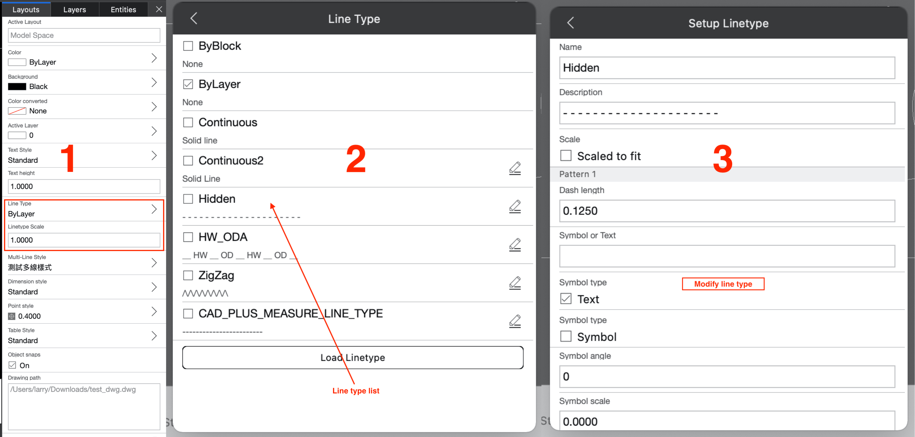
3.11 Manage Linetypes and change linetype scale
3.12 Manage Multi-line style
You can add and modify multiline styles. Multilines added to drawing later will use this style by default. 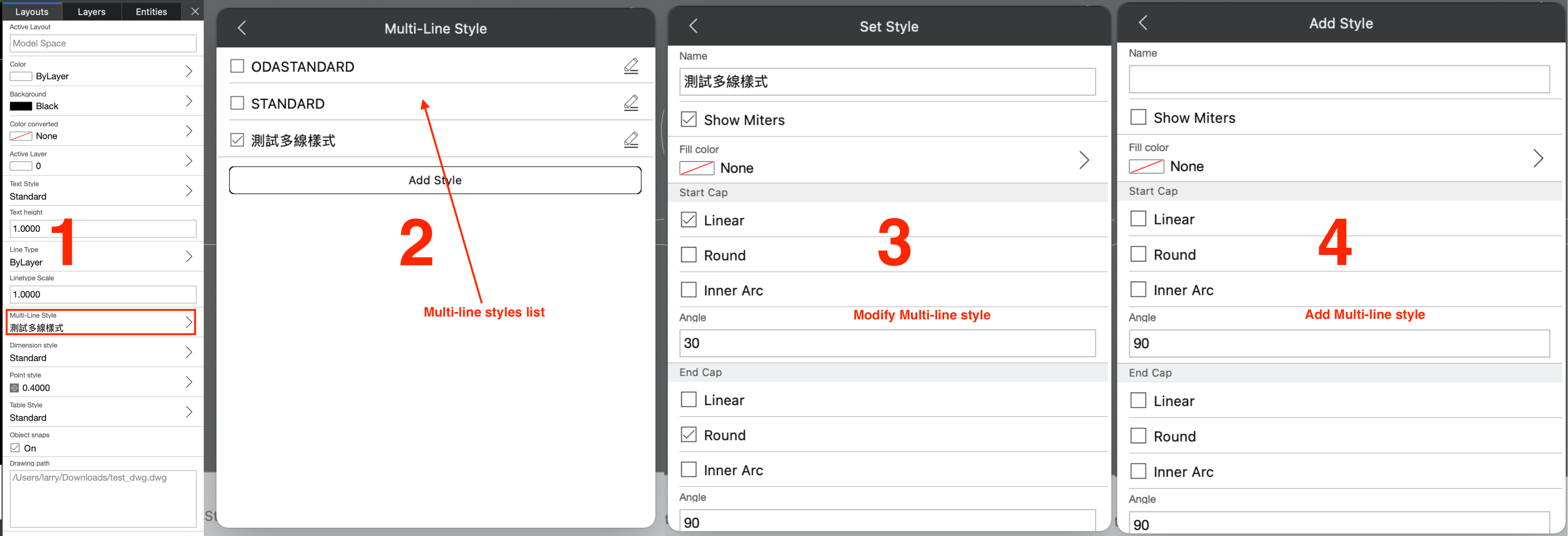
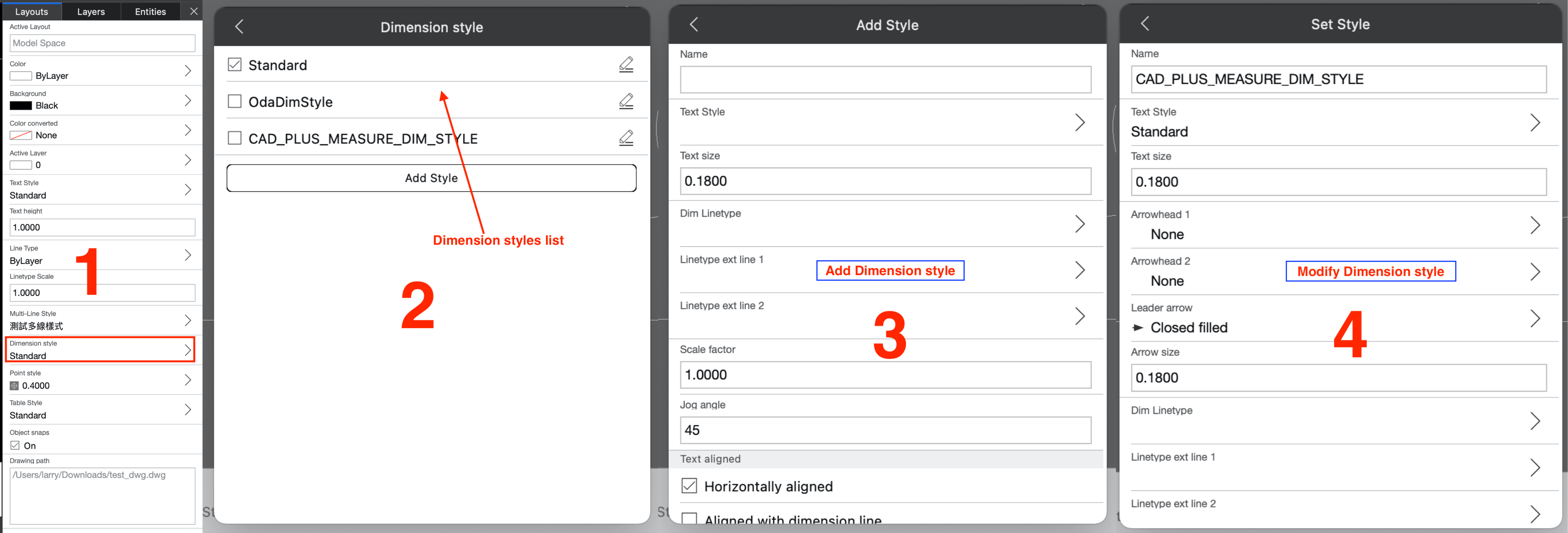
3.13 Manage Dimension style
You can add, modify, or set default dimension styles
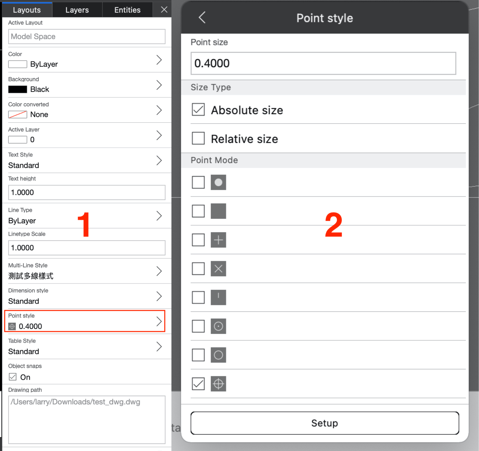
3.14 Manage Point style
Change the size or style of points. When the point object in the drawing is not displayed normally; You can correct this problem by modifying the style and size of the points.
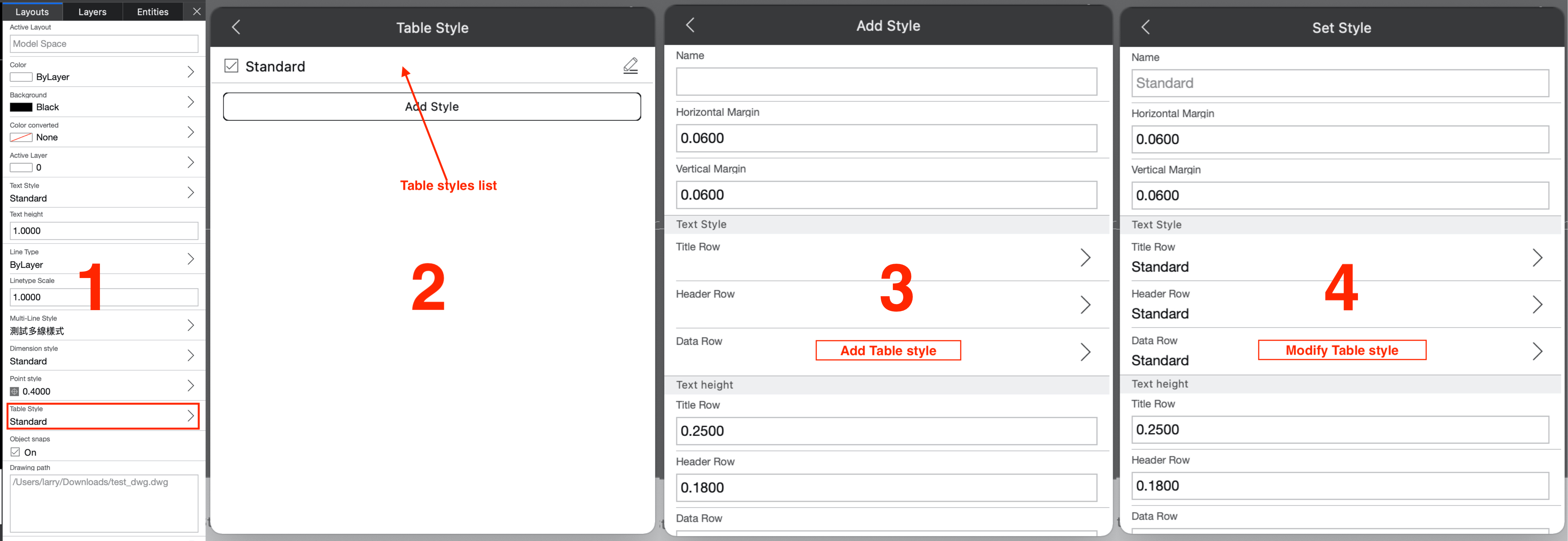
3.15 Manage Table style
You can add or modify table styles
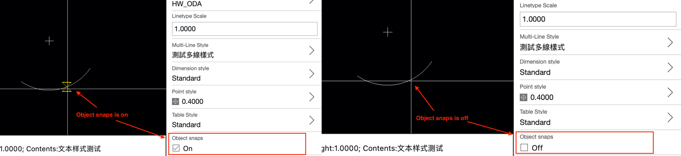
3.16 Turn on/off objects snaps
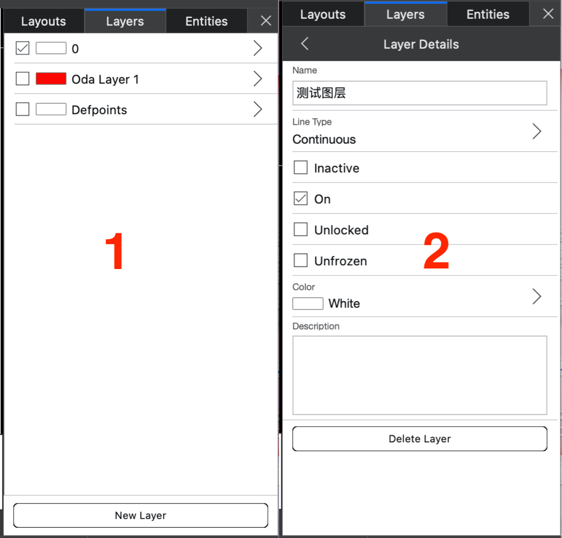
3.17 Manage layer
You can add layers, delete layers, or change the attributes of layers; Layer 0 cannot change name
3.18 Manage Entity Properties
The selected object will appear in the entity list; You can enter the entity details page to change the object's properties or delete the object

3.19 The function of the space bar
When there are no commands to execute, pressing the spacebar in the drawing window or command window will execute the last command.
If you have any questions, please send email to 3167292926@qq.com

 浙公网安备 33010602011771号