I2C协议背景知识简介与FTDI的FT4232H配成USB to I2C(MPSSE)使用实例
MPSSE Application Example:
http://ftdichip.cn/Support/SoftwareExamples/MPSSE.htm
MPSSE: AN_129 FTDI USB To JTAG TAP Example
MPSS: AN_114 FTDI USB to SPI Example
MPSSE: AN_113 FTDI USB to I2C Example
MPSS: AN_113 FTDI USB to I2C Example
Acronyms and Abbreviations
| Terms | Description |
|---|---|
| MPSSE | Multi Purpose Synchronous Serial Engine |
| I2C | Inter-Integrated Circuit |
| JTAG | Joint Test Action Group |
| SPI | Serial Peripheral Interface |
| SPI Master | A SPI device that initiates and manages serial communication to all devices connected to its SPI bus. |
| SPI Slave | A SPI device that responds to commands sent to it by the SPI master. |
| MISO | Master In, Slave Out |
| MOSI | Master Out, Slave In |
| Serial EEPROM | A programmable memory chip that uses a bitwise serial interface such as I2C or SPI. |
| USB | Universal Serial bus |
FTDI MPSSE(Multi-Protocol Synchronous Serial Engine)
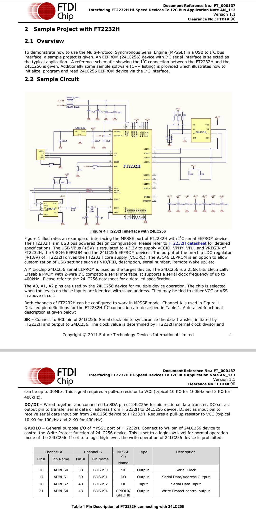
Using the MPSSE can simplify the synchronous serial protocol (USB to SPI, I2C, JTAG, etc.) design. This application note illustrates how to use the MPSSE of the FT2232H to interface with the I2C bus. The FT232H and FT4232H can also be used with the example in this document, though pin-out and port selection will need to match the respective part.
Users can use the example schematic (refer to Figure 3) and software code (section 3) to begin their design.
Note that software code listing is provided as an illustration only and not supported by FTDI.
provided as an illustration only and not supported by FTDI.
1.1 I2C Bus Introduction
I2C is a low- to medium-data-rate master/slave communication bus.:
- Two wires: SCL(serial clock) and SDA(serial data), carry information between the devices connected to the bus.
- Each device is recognized by a unique address and can operate as either a transmitter or receiver, depending on the function of the device.
- In addition to transmitters and receivers, devices can also be considered as masters or slaves when performing data transfers. A master is the device whic h initiates a data transfer on the bus. At that time, any device addressed is considered a slave.
The physical layer of I2C bus is a simple handshaking protocol that relies upon open collector outputs on the bus devices and the device driving or releasing the bus lines, so a pull-up resistor is needed on each wire of the bus.
I2C bus is a true multi-master bus including collision detection and arbitration to prevent data corruption, if two or more masters simultaneously initiate data transfer Serial, 8-bit oriented, bi-directional data transfers can be made at:
- Standard-mode: up to 100 kbit/s,
- Fast-mode: up to 400 kbit/s,
- High-speed mode: up to 3.4 Mbit/s.
Figure 1 shows typical data transfers on the I2C bus.
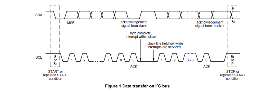
The master supplies the clock; it initiates and terminates transactions and the intended slave (based upon the address provided by the master) acknowledges the master by driving or releasing the bus. The slave cannot terminate the transaction but can indicate a desire to by a "NAK" or not-acknowledge.
I2C specification defines unique situations as S(START) and P(STOP) conditions(Figure 2):

- START and STOP conditions are always generated by the master.
- START condition: A HIGH to LOW transition on the SDA line while SCL is HIGH.
- STOP condition: A LOW to HIGH transition on the SDA line while SCL is HIGH.
- Every byte put on the SDA line must be 8-bits long. The number of bytes can be transmitted per transfer is unrestricted.
- Each byte is followed by an acknowledge bit. In most cases, data transfer with acknowledge is obligatory. The acknowledge-related clock pulse is generated by the master.
- Data is transferred with the MSB(most significant bit) first.
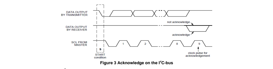
- The transmitter releases the SDA line (HIGH) during the acknowledge clock pulse. The receiver must pull down the SDA line during the acknowledge clock pulse so that it remains stable LOW during the HIGH period of this clock pulse (see Figure 3). Also, set-up and hold times must also be taken into account.
Data transfers of I2C specification should follow the format. After the START condition (S), a slave address should be sent first. This address is 7 bits long followed by an eighth bit which is a data direction bit (R/ ) – a "zero" indicates a transmission (WRITE), a "one" indicates a request for data (READ). After the slave address byte is sent, master can continue its data transfer by writing or reading data byte as defined format. The data transfer is always terminated by a STOP condition generated by the master.

 浙公网安备 33010602011771号