MCU之Microchip PIC16F17146 Curiosity NANO Evaluation Kit评测报告
对比完 RISC(Proprietary) 与 RISC-V(Open Source),来点 Microchip 的 PIC16F17146 Curiosity Nano(Revision 4 has PIC16F17146 rev B2) Evaluation Kit的实测:
一、综述
这块板是多层PCB设计,大量使用SMD(Surface Mounted Devices), 使整板轻而小(51mm20mm5mm,包括按钮开关高度), 整体才大拇指大小。既可独立使用也可对外输出或作为模块快捷组合,板载最重要的有:
- Debugger ATSAMD21E18A-U: 32bit MCU, ARM® Cortex series, come from Microchip;
- on board MCU PIC16F17146-6N: 8bit MCU, PIC® series, comefrom Microchip;
- Micro USB对外Interfere,如果是最新的 Type-C 就更好了;
- 32.768KHz的晶体震荡器 VMK3-9001-32K7680000TR ;
- 两个板载LED:
靠近Micro USB接头的是Power/Status 电源与状态指示LED
靠近User Switch的是User LED(LED0)只是对BUS/板载PIC MCU的Power/Status - 一枚机械按钮常开状态的开关 User Switch, 对Target Regulator的供电管理 5V Power BUS 和 PIC MCU的供电进行控制7. 带防短路电流检测与保护功能,以及,因此可以放心的使用。
- VBUS Output Pin 有对外供电总线输出功能(4.4V-5.25V, 1A电流能力, 带PTC保险丝)
- Debugger通过调整PCB线路,不仅可以对板载 PIC16F17146 MCU还可以对外部设备进行Programming与Debugging.
- Pin-Headers 排针方便插接Microchip的积木式组合Base Board基板。
Microchip官方有提供本板的User Guide应用指导文档、 Schematic电路图、Assembly Drawing组装图、Pinout Mapping对外端口映射图,以及其它文档与资源。
总体上定位清晰、目标明确、有系统设计思想、兼容搭积木模组化、全面、美观、实用、多功能、可扩展、节能、成本有管理、精心选用材料(大多数Microchip自家的系列)、配套软硬件齐全、文档完善。
体现Microchip公司总体的战略、文化、生态建设、用户社群与市场理念、公司管理与组织协作、软硬件系统设计、工程实施、生产制造,全球交付等的落实。
二、Board对两块MCU的设计对比:
Debugger用的 32bit ATSAMD21E18A-U 计算性能、存储能力、GPIO数 要比 on board 8bit PIC16F17146-6N 强太多,只是 PIC16F17146-6N 功能更全,而且是本Evaluation Kit设计的主角而已。
实际这完全是一块板载32bit ARM® Cortex RISC MCU 与 8bit PIC® MCU都可以同时独立使用的开发板!
因为 Debugger是一枚更强大的MCU,可以 Update firmware, 而且 通过 线路调整(剪断板背面的Programming and Debugging Connections to Debugger GPIO straps 就可以独立对外),不仅可以对 on board PIC16F17146-6N MCU 还可以对外部的 MCU 进行 Programming 与 debugging,成为一块独立的 烧录器 与 编程器。
三、Microchip官方更是提供商业级的:
User Guide/Mannual and other document文档;
商业级用户技术支持
Altium 的PCB电路设计文件,以及GITHUB hosted 的 多个示范应用 Source Code 都有
完整的全套 MPLAB® 软体:开发X IDE、商业编译器XC Compilers、MCC(Code Configurator, 自动生成驱动与硬件抽象层C Source文件)、调试Debugger(例如MPLAB® PICkit™ series)、可视化操控的 Data Visualizer、MPLAB Discover社会化/社交化项目协作的可以方便找到 collateral 和 example projects …
Microchip Xpress云端快速的开放环境www.mplab-xpresside.microchip.com/;
Microchip的 Sample Store在线申请 Sample;
直营的 Microchip 在线网上商店,全球可以提交订单采购。
Microchip官方甚至连用 Altium 设计的PCB电路设计项目文件和BOM物料单,以及GITHUB hosted 的 多个示范应用都有.
四、实拍与图片:
开箱: 两个防静电包:主PCB板+排针@PIC16F17146 Curiosity NANO Evaluation Kit

主PCB板正面照@PIC16F17146 Curiosity NANO Evaluation Kit

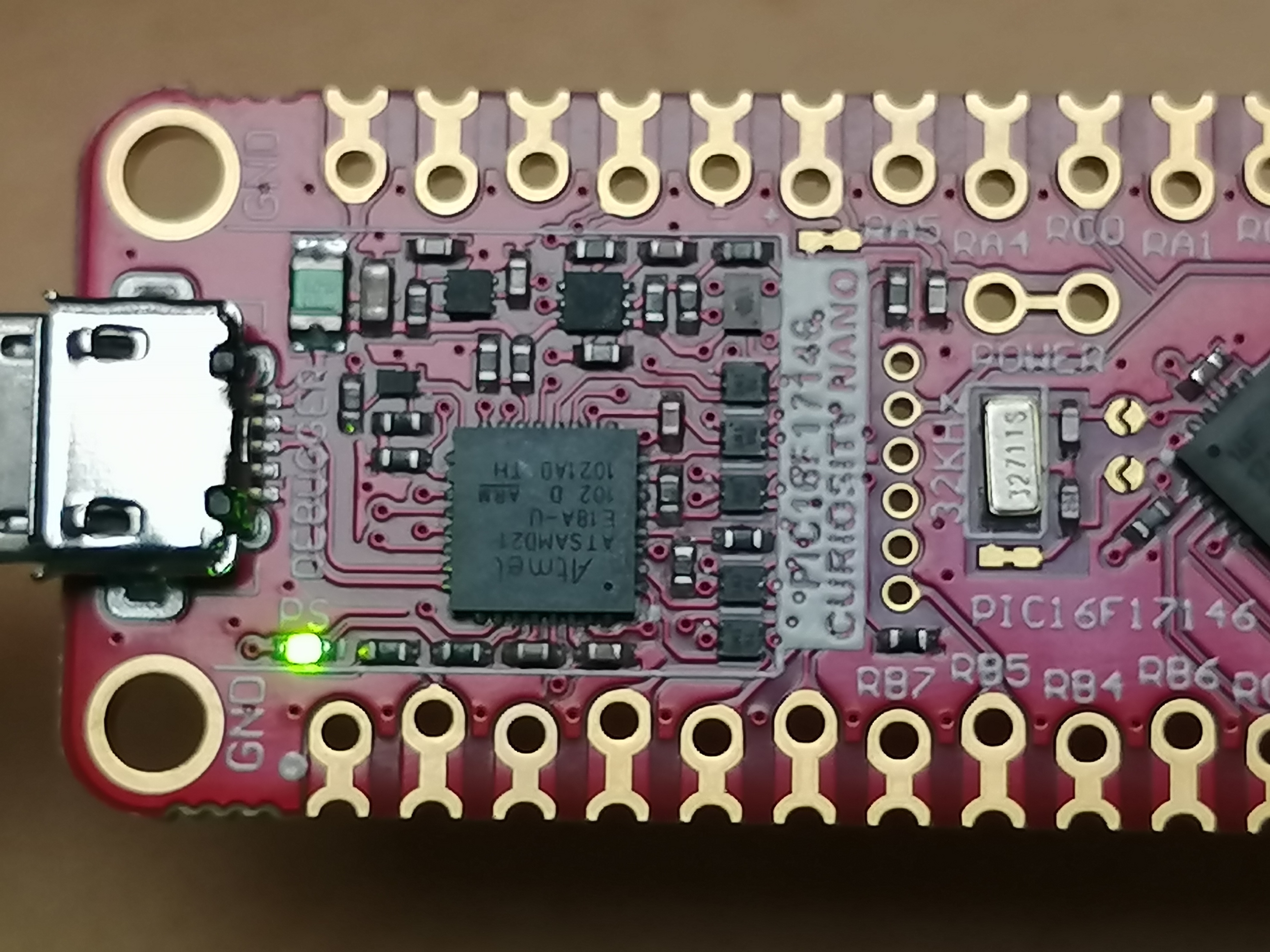
主PCB板背面照@PIC16F17146 Curiosity NANO Evaluation Kit

主PCB板连Micro USB供电@PIC16F17146 Curiosity NANO Evaluation Kit

32bit MCU: ATSAMD21E18A-U@主PCB板@PIC16F17146 Curiosity NANO Evaluation Kit
8bit MCU: PIC16F17146-6N@主PCB板@PIC16F17146-6N Curiosity NANO Evaluation Kit

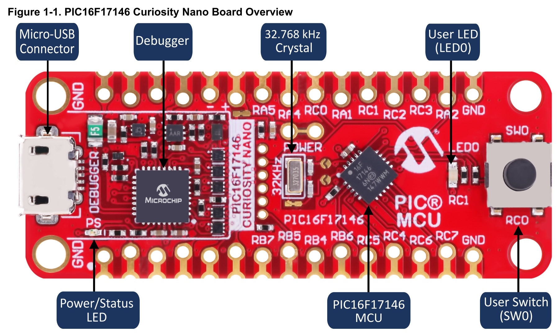
Overview@主PCB板@PIC16F17146 Curiosity NANO Evaluation Kit
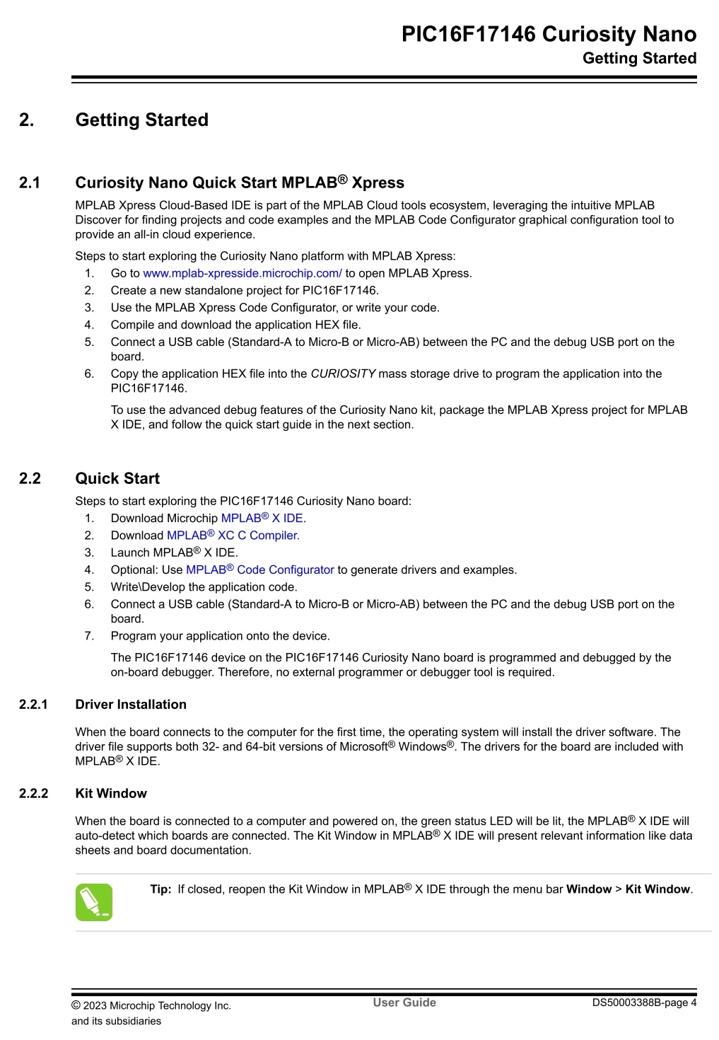
Quick Start快速启动应用@User Guide@PIC16F17146 Curiosity NANO Evaluation Kit
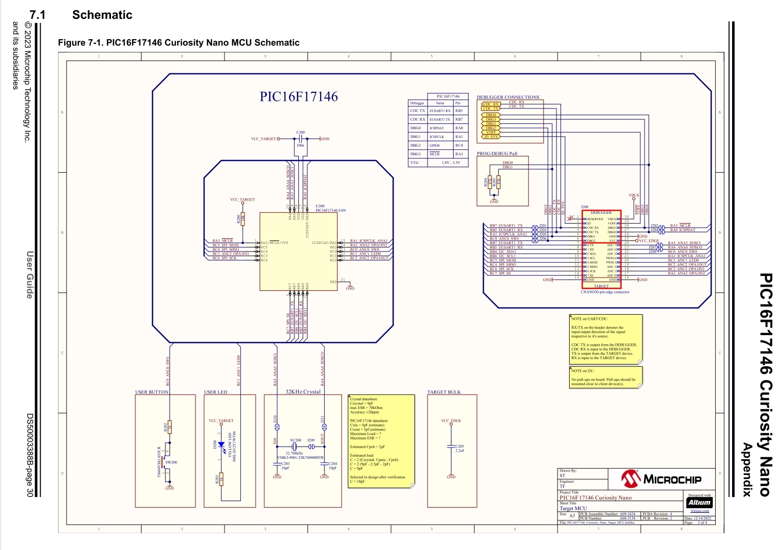
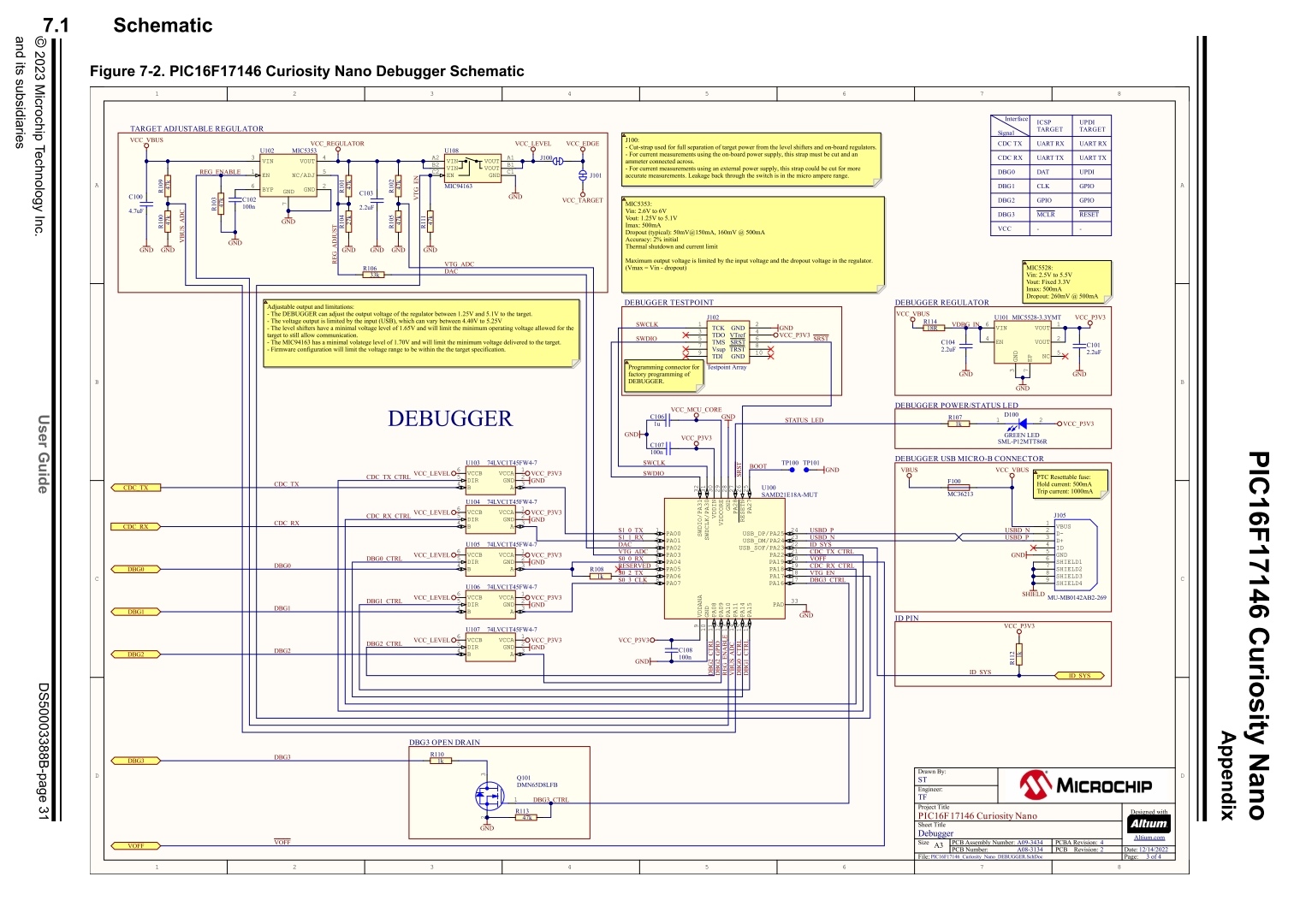
PIC16F17146-6N.Schematic@User Guide@PIC16F17146 Curiosity NANO Evaluation Kit
ATSAMD21E18A-U.Schematic@User Guide@PIC16F17146 Curiosity NANO Evaluation Kit
五、参考文献:
Evaluation Kit: PIC16F17146 curiosity NANO
Debugger: ATSAMD21E18A-U:32bit MCU, ARM®
MCU: PIC16F17146-6N, 8bit MCU, PIC series
https://www.microchip.com/en-us/product/ATSAMD21E18
ATSAMD21E18A-U: 32-bit MCU, ARM® Cortex®-M0+ based Flash MCU
Low-Power, 32-bit Cortex-M0+ MCU with Advanced Analog and PWM
Parametrics
- Part Family: SAMD21
- CPU Type: Cortex-M0+
- MaxSpeed (MHz): 48
- SRAM (KB): 32
- Program Memory Type: Flash
- Program Memory Size (KB): 256
- Temp. Range Min. to Max.: [-40, 125]
- Operation Voltage Min. to Max.(V): [1.62, 3 63]
- Direct Memory Access (DMA) Channels: 12
- SPI: 4 -SPI
- I2C: 4
- UART: 4
- Crypto Engine: No
- Internal Oscillator: 32khz, 32Khz ULP, 8Mhz
- Pin Count: 32
Product Features
- Single-cycle hardware multiplier
- Micro Trace Buffer
- 256KB in-system self-programmable Flash
- 32KB SRAM Memory
- Power-on reset (POR) and brown-out detection (BOD)
- Internal and external clock options with 48MHDigital Frequency Locked Loop (DFLL48M) and 48MHto 96MHFractional
- External Interrupt Controller (EIC)
- 16 external interrupts
- One non-maskable interrupt
- Two-pin Serial Wire Debug (SWD) programming, test and debugging interface
- Drop in compatible with SAM D20
- Idle and standby sleep modes
- SleepWalking peripherals
- 12-channel Direct Memory Access Controller (DMAC)
- 12-channel Event System
- One 16-bit TC with compare/capture channels
- One 8-bit TC with compare/capture channels
- One 32-bit TC with compare/capture channels, by using two TCs
- Up to four compare channels with optional complementary output
- Generation of synchronized pulse width modulation (PWM) pattern across port pins
- Deterministic fault protection, fast decay and configurable dead-time between complementary output
- Dithering that increase resolution with up to 5 bit and reduce quantization error
- 32-bit Real Time Counter (RTC) with clock/calendar function
- Watchdog Timer (WDT)
- CRC-32 generator
- Embedded device function
- Eight endpoints
- USART with full-duplex and single-wire half-duplex configuration
- I2C Bus up to 3.4MHz
- SMBUS/PMBUS
- SPI
- LIN client
- Differential and single-ended input
- 1/2x to 16x programmable gain stage
- Automatic offset and gain error compensation
- Oversampling and decimation in hardware to support 13-, 14-, 15- or 16-bit resolution
- 10-bit, 350ksps Digital-to-Analog Converter (DAC)
- Two Analog Comparators (AC) with window compare function
- 256-channel capacitive touch and proximity sensing
- 26 GPIO pins
- 32-pin TQSP, QFN, WLCSP
- 1.62V – 3.63V
A low-power, high-performance Microchip's ARM® Cortex®-M0+ based Flash microcontroller, the ATSAMD21E18 is ideal for a wide range of home automation, consumer, metering, and industrial applications. It features:
- 256KB of flash and 32KB of SRAM
- Up to 48MHz operating frequency
- Four serial communication modules (SERCOM) configurable as UART/USART, SPI or I2C
- three 16-bit timer/counters
- 32-bit Real-Time Clock and calendar
- 18 PWM channels
- one 14-channel 12-bit ADC
- one 10-bit DAC
- Full Speed USB Device and embedded Host
- Support for up to 60 touch channels
- 1.62V to 3.63V power supply
- Easy pin migration to SAMD21G and SAMD21J devices
- Supported by MPLAB X IDE and MPLAB Harmony.
Functional Safety
supports the ISO 26262 (ASIL B), IEC 61508 (SIL 2) and IEC 60730 (Class B) functional safety standards.
· The Functional Safety Manual, FMEDA and information on the Diagnostic Software are available under NDA through the request form on the 32-bit Microcontrollers Functional Safety web page.
· To request any information about the SIL 2 STL, please fill out and submit the request form on Industrial Safety Self-Test Library web page.
· Learn more about 32-bit MCUs with Functional Safety capabilities including device hardware and certified software libraries.
https://www.microchip.com/en-us/product/PIC16F17146PIC16F17146: 8-bit RISC 32MHz Full-Featured 20Pin MCU
The PIC16F171xx family’s advanced analog peripherals are specifically well-suited for raw sensor applications requiring signal gain or filtering.
It is the first product family to offer a low-noise Operational Amplifier (Op-Amp), a 12-bit differential ADC with Computation (ADCC). it also includes two 8-bit Digital-to-Analog Converters (DAC), up to four 16-bit Pulse-Width Modulation (PWM) peripherals, and many more waveform control and communication peripherals.
This small form factor, feature-rich device is well suited for low-cost, energy-efficient analog sensor applications with higher resolution requirements.
Parametrics:
- CPU Speed (MIPS/DMIPS): 8
- Data EEPROM (bytes): 256
- Program Memory Type: Flash
- Program Memory Size (KB): 28
- Timers: 2 x 8-bit - 2 x 16-bit
- Stand alone PWM: 2
- Number of ADCs: 1
- Diff ADC Inputs: 17
- ADC Channels: 17
- Max ADC Resolution (bits): 12
- Number of Comparators: 2
- Temp. Range Min. to Max. : [-40, 125]
- Operation Voltage Min. to Max(V): [1.8, 5.5]
- Low Power: Yes
- I2C: 0 -I2C
- Pin Count: 20
Product Features
- Enhanced Mid-range Core with 49 Instructions, 16 Stack Levels
- Flash Program Memory with Self Read/Write Capability
- eXtreme Low Power (XLP)
- IDLE and DOZE low power modes
- Peripheral Module Disable (PMD)
- Peripheral Pin Select (PPS)
- 12-bit Differential Analog-to-Digital Converter with Computation (ADCC)
- 1x Op-Amp
- 2x Capture/Compare/PWM (CCP)
- 2x 16-bit PWM with Dual Outputs
- 1x 8-bit Internal Digital-to-Analog Converters (DAC)
- 1x 8-bit External/Buffered Digital-to-Analog Converter (DAC)
- x2 Analog Comparators (AC)
- x4 Configurable Logic Cells (CLC)
- Flash CRC
- 1x NCO
- 1x CWG
- Zero-Cross Detect (ZCD)
- 2x EUSART(with LIN support)
- 2x MSSP (I2C or SPI)
- 1x 8/16-bit Timer (TMR0)
- 1x 16-bit Timer (TMR1)
- 1x 8-bit Timer (TMR2)
- Enhanced Power-On/Off-Reset
- Programmable Brown-Out Reset (BOR) with fast recovery

 浙公网安备 33010602011771号