

基于面绘制的MC算法以及基于体绘制的 Ray-casting 实现Dicom图像的三维重建(python实现)
加入实验室后,经过张老师的介绍,有幸与某公司合共共同完成某个项目,在此项目中我主要负责的是三维 pdf 报告生成、Dicom图像上亮度、对比度调整以及 Dicom图像三维重建。今天主要介绍一下完成Dicom图像三维重建的过程以及自己的心得体会。实现Dicom三维图像重建最主要用的VTK(Visualization Toolkit,也就是可视化工具包),由于今天的主题不是有关VTK,所以有关VTK的学习(包括VTK介绍、使用、实列),可以参考此链接:https://blog.csdn.net/wishchin/article/details/12996693,个人建议:先把此教程中的前3个章节看完之后,在看此教程,这样能够更好的理解程序。接下来就让我们进入正题。
VTK将在可视化过程中经常遇到的细节屏蔽起来,并封装了一些常用的可视化算法,如将面绘制中常用的MC(MarchingCubes)算法和体绘制中常用的光线投射(Ray-Casting)算法封装成类的形式提供给使用者。这样在进行医学体数据的可视化时就可以直接使用VTK中已提供的相关类
整个项目的代码以及挂在GitHub上:https://github.com/tgpcai/Dicom_3D_Reconstruction,觉得哈不错的可以给楼主点一个start~
0.三维可视化的两种方式
(1)简单点说,三维可视化的目的就是让人们从屏幕上看到三维图像中有什么东西。众所周知,二维图像的显示是容易的,但是三维图像却不一样。过去由于技术的限制,得到了三维图像的数据,只能把它以二维图像的切片的形式展示给人看,这样显然不够直观。随着计算机科学的发展,使用计算机图形学技术为三维物体建模并实时渲染,实现场景漫游变成显示三维物体的主流方法,而过去切片显示的方式则逐渐被边缘化。
(2)由计算机图形学的知识我们可以知道,想显示三维图像中的内容,可以对这个“内容”的表面建立一个三角形网格模型。一旦得到了这个三角网格,那么渲染它就能够在屏幕上看到想要的内容,同时可以调节视角进行全方位的观察。所以第一类三维可视化方法就是基于这种思想:首先建立网格模型,之后渲染网格。这种方式被称为面绘制。
(3)还有一种叫做体绘制的方式,是直接将三维图像的体素点通过一定的透明度叠加计算后直接对屏幕上的像素点着色。这种方式的特点是能更加清楚的表现体数据内部细节,但是这种算法一般对计算机的压力也会比较大。
1.基于面绘制的MC算法
(0)首先基于MC的一系列算法需要明确一个“体元(Cell)”的概念。体元是在三维图像中由相邻的八个体素点组成的正方体方格,MarchingCubes算法的Cube的语义也可以指这个体元。注意区别体元和体素,体元是8个体素构成的方格,而每个体素(除了边界上的之外)都为8个体元所共享。
(1)面绘制:面绘制是采用分割技术对一系列的二维图像进行轮廓识别、提取等操作,最终还原出被检测物体的三维模型,并以表面的方式显示出来。
(2)面绘制实现三维重建。使用的是经典的 Marching Cubes 算法,也叫移动立方体法。
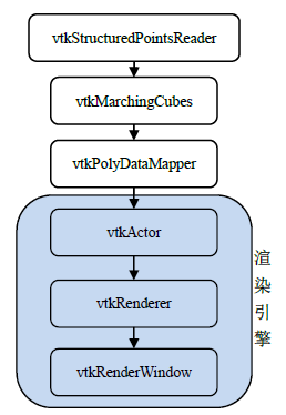
(3)采用面绘制,VTK中的数据流如下:source->filter(MC算法或者vtkContourFilter)->mapper->actor->render->renderwindow->interactor。
(4)MC算法简介:
- 首先,假定原始数据是离散的三维空间规则数据场,(断层扫描仪CT及核磁共振仪MRI产生的图像均属于这一类型),读取这些数据,可得出这些数据的三个维度。
- 其次,以体元为单位来寻找三维图像中内容部分与背景部分的边界,在体元抽取三角片来拟合这个边界。
- 再者,遍历所有的体元,找出其中的三角片最后集合起来组成图像中实点表面的三角网格(Mesh)。
- 最后,建立好了三角形网格模型,对该模型进行渲染。
(5)VTK提供了两种提取等值面的类:vtkContourFilter滤波器和封装了MC(Marching Cubes)算法类vtkMarchingCubes。提取等值面之后的数据处理:通过vtkPolyDataNormals在等值面上产生法向量;通过vtkStripper在等值面上产生纹理或三角面片。
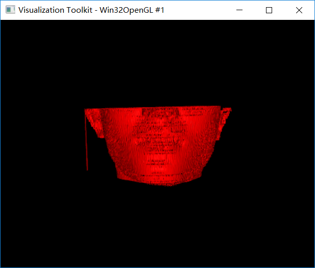
(6)利用MC算法提取等值面的代码实现:
 1 import vtk
 2 # source->filter(MC算法)->mapper->actor->render->renderwindow->interactor
 3
 4 # 读取Dicom数据,对应source
 5 v16 = vtk.vtkDICOMImageReader()
 6 # v16.SetDirectoryName('D:/dicom_image/V')
 7 v16.SetDirectoryName('D:/dicom_image/vtkDicomRender-master/sample')
 8
 9 # 利用封装好的MC算法抽取等值面,对应filter
10 marchingCubes = vtk.vtkMarchingCubes()
11 marchingCubes.SetInputConnection(v16.GetOutputPort())
12 marchingCubes.SetValue(0, 100)
13
14 # 剔除旧的或废除的数据单元,提高绘制速度,对应filter
15 Stripper = vtk.vtkStripper()
16 Stripper.SetInputConnection(marchingCubes.GetOutputPort())
17
18 # 建立映射,对应mapper
19 mapper = vtk.vtkPolyDataMapper()
20 # mapper.SetInputConnection(marchingCubes.GetOutputPort())
21 mapper.SetInputConnection(Stripper.GetOutputPort())
22
23 # 建立角色以及属性的设置,对应actor
24 actor = vtk.vtkActor()
25 actor.SetMapper(mapper)
26 # 角色的颜色设置
27 actor.GetProperty().SetDiffuseColor(1, .94, .25)
28 # 设置高光照明系数
29 actor.GetProperty().SetSpecular(.1)
30 # 设置高光能量
31 actor.GetProperty().SetSpecularPower(100)
32
33 # 定义舞台,也就是渲染器,对应render
34 renderer = vtk.vtkRenderer()
35
36 # 定义舞台上的相机,对应render
37 aCamera = vtk.vtkCamera()
38 aCamera.SetViewUp(0, 0, -1)
39 aCamera.SetPosition(0, 1, 0)
40 aCamera.SetFocalPoint(0, 0, 0)
41 aCamera.ComputeViewPlaneNormal()
42
43 # 定义整个剧院(应用窗口),对应renderwindow
44 rewin = vtk.vtkRenderWindow()
45
46 # 定义与actor之间的交互,对应interactor
47 interactor = vtk.vtkRenderWindowInteractor()
48
49 # 将相机添加到舞台renderer
50 renderer.SetActiveCamera(aCamera)
51 aCamera.Dolly(1.5)
52
53 # 设置交互方式
54 style = vtk.vtkInteractorStyleTrackballCamera()
55 interactor.SetInteractorStyle(style)
56
57 # 将舞台添加到剧院中
58 rewin.AddRenderer(renderer)
59 interactor.SetRenderWindow(rewin)
60
61 # 将角色添加到舞台中
62 renderer.AddActor(actor)
63
64 # 将相机的焦点移动至中央,The camera will reposition itself to view the center point of the actors,
65 # and move along its initial view plane normal
66 renderer.ResetCamera()
67
68 interactor.Initialize()
69 interactor.Start()
结果如下:
(7)利用vtkContourFilter滤波器提取等值面的代码实现:
  1 # 抽取轮廓(等值面)的操作对象是标量数据。
  2 # 其思想是:将数据集中标量值等于某一指定恒量值的部分提取出来。对于3D的数据集而言,产生的是一个等值面;对于2D的数据集而言,产生的是一个等值线。
  3 # 其典型的应用有气象图中的等温线、地形图中的等高线。对于医学数据而言,不同的标量值代表的是人体的不同部分,因而可以分别提取出人的皮肤或骨头。
  4 # 抽取轮廓的功能是由一个过滤器实现的,如vtkContourFilter、vtkMarchingCubes。vtkContourFilter可以接受任意数据集类型作为输入,因而具有 一般性。
  5 # 使用vtkContourFilter 时,除了需要设置输入数据集外,还需要指定一个或多个用于抽取的标量值。可用如下两种方法进行设置。
  6 #
  7 # 使用方法SetValue()逐个设置抽取值。该方法有个两个参数:第一个参数是抽取值的索引号,表示第几个 抽取值。索引号从0开始计数;第二个参数就是指定的抽取值。
  8 # 使用方法GenerateValues()自动产生一系列抽取值。该方法有三个参数:第一个参数是抽取值的个数,后面两个参数是抽取值的取值范围。
  9
 10 # coding=utf-8
 11 import vtk
 12
 13 # source—filter——mapper——actor——render——renderwindow——interactor
 14 aRenderer = vtk.vtkRenderer()  # 渲染器
 15 renWin = vtk.vtkRenderWindow()  # 渲染窗口,创建窗口
 16 renWin.AddRenderer(aRenderer)  # 渲染窗口
 17 # renWin.Render()
 18 iren = vtk.vtkRenderWindowInteractor()  # 窗口交互
 19 iren.SetRenderWindow(renWin)
 20
 21 # The following reader is used to read a series of 2D slices(images)
 22 # that compose the volume.Theslicedimensions are set, and the
 23 #  pixel spacing.The data Endianness must also be specified.The reader
 24 #  uses the FilePrefix in combination with the slice number to construct
 25 # filenames using the format FilePrefix. % d.(In this case the FilePrefix
 26 # is the root name of the file.
 27
 28 v16 = vtk.vtkDICOMImageReader()
 29 # v16.SetDirectoryName('D:/dicom_image/V')
 30 v16.SetDirectoryName('D:/dicom_image/vtkDicomRender-master/sample')
 31
 32
 33
 34 # An isosurface, or contour value of 500 is known to correspond to the
 35 # skin of the patient.Once generated, a vtkPolyDataNormals filter is
 36 # used to create normals for smooth surface shading during rendering.
 37 skinExtractor = vtk.vtkContourFilter()
 38 skinExtractor.SetInputConnection(v16.GetOutputPort())
 39 skinExtractor.SetValue(0, -10)
 40 # skinExtractor.GenerateValues(2, 100, 110)
 41 skinNormals = vtk.vtkPolyDataNormals()
 42 skinNormals.SetInputConnection(skinExtractor.GetOutputPort())
 43 skinNormals.SetFeatureAngle(60.0)
 44 skinMapper = vtk.vtkPolyDataMapper()  # 映射器
 45 skinMapper.SetInputConnection(skinNormals.GetOutputPort())
 46 skinMapper.ScalarVisibilityOff()
 47
 48 skin = vtk.vtkActor()
 49 # 设置颜色RGB颜色系统就是由三个颜色分量:红色(R)、绿色(G)和蓝色(B)的组合表示,
 50 # 在VTK里这三个分量的取值都是从0到1,(0, 0, 0)表示黑色,(1, 1, 1)表示白色。
 51 #  vtkProperty::SetColor(r,g, b)采用的就是RGB颜色系统设置颜色属性值。
 52 #skin.GetProperty().SetColor(0, 0, 1)
 53 skin.SetMapper(skinMapper)
 54
 55 skin.GetProperty().SetDiffuseColor(1, .49, .25)
 56
 57 skin.GetProperty().SetSpecular(.5)
 58
 59 skin.GetProperty().SetSpecularPower(20)
 60
 61 # skin.GetProperty().SetRepresentationToSurface()
 62 # 构建图形的方框
 63 outlineData = vtk.vtkOutlineFilter()
 64 outlineData.SetInputConnection(v16.GetOutputPort())
 65 mapOutline = vtk.vtkPolyDataMapper()
 66 mapOutline.SetInputConnection(outlineData.GetOutputPort())
 67 outline = vtk.vtkActor()
 68 outline.SetMapper(mapOutline)
 69 outline.GetProperty().SetColor(0, 0, 0)
 70
 71 # 构建舞台的相机
 72 aCamera = vtk.vtkCamera()
 73 aCamera.SetViewUp(0, 0, -1)
 74 aCamera.SetPosition(0, 1, 0)
 75 aCamera.SetFocalPoint(0, 0, 0)
 76 aCamera.ComputeViewPlaneNormal()
 77
 78 # Actors are added to the renderer.An initial camera view is created.
 79 # The Dolly() method moves the camera towards the Focal Point,
 80 # thereby enlarging the image.
 81 aRenderer.AddActor(outline)
 82 aRenderer.AddActor(skin)
 83 aRenderer.SetActiveCamera(aCamera)
 84 # 将相机的焦点移动至中央,The camera will reposition itself to view the center point of the actors,
 85 # and move along its initial view plane normal
 86 aRenderer.ResetCamera()
 87 # aCamera.Dolly(1.5)
 88 # aCamera.Roll(180)
 89 # aCamera.Yaw(60)
 90
 91 aRenderer.SetBackground(250, 250, 250)
 92 # renWin.SetSize(640, 480)
 93 # 该方法是从vtkRenderWindow的父类vtkWindow继承过来的,用于设置窗口的大小,以像素为单位。
 94 renWin.SetSize(500, 500)
 95 aRenderer.ResetCameraClippingRange()
 96
 97 style = vtk.vtkInteractorStyleTrackballCamera()
 98 iren.SetInteractorStyle(style)
 99
100 iren.Initialize()
101 iren.Start()
结果如下:

(8)与可视化窗口的交互方式:可以使用鼠标与三维图形交互,比如用鼠标滚轮可以对三维图形放大、缩小;按下鼠标左键不放,然后移动鼠标,可以转动三维图形;按下鼠标左键,同时按下Shift键,移动鼠标,可以移动整个三维图形,等等。其他的功能你也可以试着摸索一下,比如按下Ctrl键时再按鼠标左键;鼠标停留在柱体上,然后按下P键;按一下字母E将关闭窗口。
(9)整个过程的简要总结:
(a)读取数据以及数据处理:首先,读取切片数据,并将其转换为我们的开发工具VTK所支持的一种数据表达形式(vtkImageData)。我们给CT数据建立的是比较抽象的等值面模型,最后将物理组件与抽象的模型结合在一起来建立对CT 数据的可视化,以帮助用户正确理解数据。利用VTK中的vtkDICOMImageReader 我们可以很方便的读取切片数据。
(b)提取等值面:接着我们就可以用算法对所读取的数据进行处理了。比如采用的经典MC的面绘制方法,首先利用vtkMarchingCubes 类来提取出某一CT值的等值面(利用vtksetValue()来设置需要提取的值),但这时的等值面其实仍只是一些三角面片,还必须由vtkStripper类将其拼接起来形成连续的等值面。这样就把读取的原始数据经过处理转换为应用数据,也即由原始的点阵数据转换为多边形数据然后由vtkPolyDataMapper将其映射为几何数据,并将其属性赋给窗口中代表它的演员,将结果显示出来。在实际应用中Visualization Toolkit支持多表面重建。我们可以设置多个参数值,提取出多个等值面并同时显示出来,如何设置多个参数值呢?可以通过VTK自带的GenerateValues()函数。常见的比如人体皮肤所对应的value值为500,人体骨骼所对应的value值为1150。
(c)显示结果:通过前面这些工作,我们基本上已经完成了对数据的读取处理映射等步骤,下面我们就要对数据进行显示了。通常这些步骤也叫做渲染引擎。可以通过调整value值和actor的相应属性达到重建三维图形的不同效果。
 最主要就是设置相机,设置actor的相关属性(颜色,亮度,透明度等等)。
2.基于体绘制的 Ray-casting算法
(1)体绘制:体绘制是将三维空间的离散数据直接转换为最后的立体,图像而不必生成中间几何图元(面绘制需要), 其中心思想是为每一个体素指定一个不透明度,并考虑每一个体素对光线的透射、发射和反射作用。
(2)体绘制达到的效果:体绘制的目标是在一副图片上展示空间体细节。举例而言,你面前有一间房子,房子中有家具、家电,站在房子外面只能看到外部形状(类似于面绘制的效果),无法观察到房子的布局或者房子中的物体;假设房子和房子中的物体都是半透明的,这样你就可以同时查看到所有的细节。这就是体绘制所要达到的效果。
(3)体绘制常用的算法:光线投射算法( Ray-casting )、错切 - 变形算法( Shear-warp )、频域体绘制算法( Frequency Domain )和抛雪球算法( Splatting )。其中又以光线投射算法最为重要和通用。
(4)光线投射算法( Ray-casting )原理:从图像平面的每个像素都沿着视线方向发出一条射线,此射线穿过体数据集,按一定步长进行采样,由内插计算每个采样点的颜色值和不透明度,然后由前向后或由后向前逐点计算累计的颜色值和不透明度值,直至光线完全被吸收或穿过物体。该方法能很好地反映物质边界的变化,使用Phong模型,引入镜面反射、漫反射和环境反射能得到很好的光照效果,在医学上可将各组织器官的性质属性、形状特征及相互之间的层次关系表现出来,从而丰富了图像的信息。(借鉴百度百科)
(5)体绘制的原理和面绘制完全不相同。面绘制需要生成中间图元,而体绘制则是直接在原图上进行绘制,内容需求较面绘制小。每切换一个视角需要重新对所有的像素点进行颜色和透明度计算,需要时间比面绘制长。
(6)代码实现基于体绘制的 Ray-casting算法
  1 # This example reads a volume dataset and displays it via volume rendering(体绘制).
  2
  3 import vtk
  4 from vtk.util.misc import vtkGetDataRoot
  5
  6 # Create the renderer, the render window, and the interactor. The renderer
  7 # draws into the render window, the interactor enables mouse- and
  8 # keyboard-based interaction with the scene.
  9 ren = vtk.vtkRenderer()
 10 renWin = vtk.vtkRenderWindow()
 11 renWin.AddRenderer(ren)
 12 iren = vtk.vtkRenderWindowInteractor()
 13 iren.SetRenderWindow(renWin)
 14
 15 # The following reader is used to read a series of 2D slices (images)
 16 # that compose the volume. The slice dimensions are set, and the
 17 # pixel spacing. The data Endianness must also be specified. The reader
 18 # usese the FilePrefix in combination with the slice number to construct
 19 # filenames using the format FilePrefix.%d. (In this case the FilePrefix
 20 # is the root name of the file: quarter.)
 21
 22 # v16 = vtk.vtkVolume16Reader()
 23 # v16.SetDataDimensions(64, 64)
 24 # v16.SetImageRange(1, 93)
 25 # v16.SetDataByteOrderToLittleEndian()
 26 # v16.SetFilePrefix("D:/dicom_image/headsq/quarter")
 27 # v16.SetDataSpacing(3.2, 3.2, 1.5)
 28 v16 = vtk.vtkDICOMImageReader()
 29 # v16.SetDirectoryName('D:/dicom_image/vtkDicomRender-master/sample')
 30 v16.SetDirectoryName('D:/dicom_image/V')
 31
 32 # The volume will be displayed by ray-cast alpha compositing.
 33 # A ray-cast mapper is needed to do the ray-casting, and a
 34 # compositing function is needed to do the compositing along the ray.
 35 volumeMapper = vtk.vtkGPUVolumeRayCastMapper()
 36 volumeMapper.SetInputConnection(v16.GetOutputPort())
 37 volumeMapper.SetBlendModeToComposite()
 38
 39 # The color transfer function maps voxel intensities to colors.
 40 # It is modality-specific, and often anatomy-specific as well.
 41 # The goal is to one color for flesh (between 500 and 1000)
 42 # and another color for bone (1150 and over).
 43 volumeColor = vtk.vtkColorTransferFunction()
 44 volumeColor.AddRGBPoint(0,    0.0, 0.0, 0.0)
 45 volumeColor.AddRGBPoint(500,  1.0, 0.5, 0.3)
 46 volumeColor.AddRGBPoint(1000, 1.0, 0.5, 0.3)
 47 volumeColor.AddRGBPoint(1150, 1.0, 1.0, 0.9)
 48
 49 # The opacity transfer function is used to control the opacity
 50 # of different tissue types.
 51 volumeScalarOpacity = vtk.vtkPiecewiseFunction()
 52 volumeScalarOpacity.AddPoint(0,    0.00)
 53 volumeScalarOpacity.AddPoint(500,  0.15)
 54 volumeScalarOpacity.AddPoint(1000, 0.15)
 55 volumeScalarOpacity.AddPoint(1150, 0.85)
 56
 57 # The gradient opacity function is used to decrease the opacity
 58 # in the "flat" regions of the volume while maintaining the opacity
 59 # at the boundaries between tissue types.  The gradient is measured
 60 # as the amount by which the intensity changes over unit distance.
 61 # For most medical data, the unit distance is 1mm.
 62 volumeGradientOpacity = vtk.vtkPiecewiseFunction()
 63 volumeGradientOpacity.AddPoint(0,   0.0)
 64 volumeGradientOpacity.AddPoint(90,  0.5)
 65 volumeGradientOpacity.AddPoint(100, 1.0)
 66
 67 # The VolumeProperty attaches the color and opacity functions to the
 68 # volume, and sets other volume properties.  The interpolation should
 69 # be set to linear to do a high-quality rendering.  The ShadeOn option
 70 # turns on directional lighting, which will usually enhance the
 71 # appearance of the volume and make it look more "3D".  However,
 72 # the quality of the shading depends on how accurately the gradient
 73 # of the volume can be calculated, and for noisy data the gradient
 74 # estimation will be very poor.  The impact of the shading can be
 75 # decreased by increasing the Ambient coefficient while decreasing
 76 # the Diffuse and Specular coefficient.  To increase the impact
 77 # of shading, decrease the Ambient and increase the Diffuse and Specular.
 78 volumeProperty = vtk.vtkVolumeProperty()
 79 volumeProperty.SetColor(volumeColor)
 80 volumeProperty.SetScalarOpacity(volumeScalarOpacity)
 81 # volumeProperty.SetGradientOpacity(volumeGradientOpacity)
 82 volumeProperty.SetInterpolationTypeToLinear()
 83 volumeProperty.ShadeOn()
 84 volumeProperty.SetAmbient(0.9)
 85 volumeProperty.SetDiffuse(0.9)
 86 volumeProperty.SetSpecular(0.9)
 87
 88 # The vtkVolume is a vtkProp3D (like a vtkActor) and controls the position
 89 # and orientation of the volume in world coordinates.
 90 volume = vtk.vtkVolume()
 91 volume.SetMapper(volumeMapper)
 92 volume.SetProperty(volumeProperty)
 93
 94 # Finally, add the volume to the renderer
 95 ren.AddViewProp(volume)
 96
 97 # Set up an initial view of the volume.  The focal point will be the
 98 # center of the volume, and the camera position will be 400mm to the
 99 # patient's left (which is our right).
100 camera = ren.GetActiveCamera()
101 c = volume.GetCenter()
102 camera.SetFocalPoint(c[0], c[1], c[2])
103 camera.SetPosition(c[0] + 400, c[1], c[2])
104 camera.SetViewUp(0, 0, -1)
105
106 # Increase the size of the render window
107 renWin.SetSize(640, 480)
108
109 # Interact with the data.
110 iren.Initialize()
111 renWin.Render()
112 iren.Start()
结果如下:

(7)体绘制的整个过程包括VTK数据量都与面绘制类似。同样可以通过调整actor的相应属性达到重建三维图形的不同效果,比如通过设置不透明度值来显示体数据内部的不同成分和细节,例如显示人体CT图像的不同器官和组织。
3.心得体会与总结
(1)其实无论是面绘制还是体绘制都需要一定的VTK知识,所以先了解VTK的一些基础知识才能帮助你更好的掌握这些方法。
(2)有关VTK整个数据流的过程可以用一下的例子进行类比,方便理解(虽然这个类比不是非常形象):
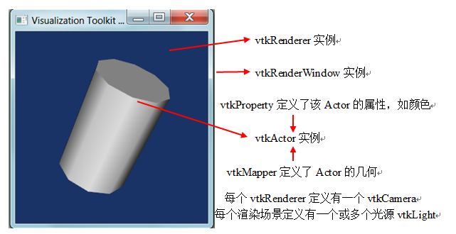
- 当我们去看舞台剧的时候,我们坐在台下,展现在我们面前的是一个舞台,舞台上有各式的灯光,各样的演员。演员出场的时候肯定是会先化妆,有些演员可能会打扮成高富帅,有些演员可能会化妆成白富美。观众有时还会与台上的演员有一定的互动。
- 整个剧院就好比VTK程序的渲染窗口(vtkRenderWindow);舞台就相当于渲染场景(vtkRenderer);而那些高富帅、白富美就是我们程序中的Actor(有些文献翻译成“演员”,有些翻译成“角色”,这里我们不作翻译);台上的演员与台下观众的互动可以看成是程序的交互(vtkRenderWindowInteractor);演员与观众的互动方式有很多种,现场的观众可以直接上台跟演员们握手拥抱,电视机前的可以发短信,电脑、移动终端用户等可以微博关注、加粉等等,这就好比我们程序里的交互器样式(vtkInteractorStyle);
- 舞台上的演员我们都能一一分辨出来,不会把高富帅弄混淆,是因为他们化的妆、穿的服饰都不一样,这就相当于我们程序里vtkActor的不同属性(vtkProperty);台下观众的眼睛可以看作是vtkCamera,前排的观众因为离得近,看台上演员会显得比较高大,而后排的观众看到的会显得小点,每个观众看到的东西在他的世界里都是唯一的,所以渲染场景Renderer里的vtkCamera对象也是只有一个;舞台上的灯光可以有多个,所以渲染场景里的vtkLight也存在多个
- 如下图所示,可以加深理解
![]()
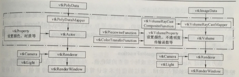
(3)体绘制与面绘制管线上的区别
- 在面绘制中,用到vtkActor或其子类的例子采用的渲染技术都是几何渲染,即通过绘制几何图元(顶点、线段、面片等)来渲染数据。
- 首先我们看下几何渲染管线和体绘制渲染管线对比,如下图所示。可以看出,体绘制渲染线和几何渲染线的组成是比较一致的,不同在于:在几何渲染中,通常使用vtkActor来渲染几何图形数据,在体绘制中则使用vtkVolume渲染数据;在几何渲染中,通常采用vtkPolyDataMapper实现输入数据向图元的转换,在体绘制中,则采用vtkVolumeRayCastMapper,这是与体绘制算法有关的,不同的体绘制算法会有不同的Mapper类。
![]()
参考文献:https://vtk.org/doc/nightly/html/annotated.html
http://blog.sina.com.cn/s/blog_5ff6097b0100zz2y.html
以上就是本次学习的内容,欢迎交流与讨论

 浙公网安备 33010602011771号