Linux驱动之GPIO子系统和pinctrl子系统
前期知识
1.如何编写一个简单的Linux驱动(一)——驱动的基本框架
2.如何编写一个简单的Linux驱动(二)——设备操作集file_operations
3.如何编写一个简单的Linux驱动(三)——完善设备驱动
4.Linux驱动之设备树的基础知识
前言
在学习单片机(比如51单片机和STM32)的时候,我们可以直接对单片机的寄存器进行操作,进而达到控制pin脚的目的。而Linux系统相较于一个单片机系统,要庞大而复杂得多,因此在Linux系统中我们不能直接对pin脚进行操作。Linux系统讲究驱动分层,pinctrl子系统和GPIO子系统就是驱动分层的产物。如果我们要操作pin脚,就必须要借助pinctrl子系统和GPIO子系统。
pinctrl子系统的作用是pin config(引脚配置)和pin mux(引脚复用),而如果pin脚被复用为了GPIO(注意:GPIO功能只是pin脚功能的一种),就需要再借助GPIO子系统对pin脚进行控制了,GPIO子系统提供了一系列关于GPIO的API函数,供我们调用。本章,我们会使用pinctrl子系统和GPIO子系统来完成对GPIO的操作。
本章的驱动代码和用户程序代码要在"如何编写一个简单的Linux驱动(三)——完善设备驱动"这一章所写的代码基础上进行修改。如果要下载"如何编写一个简单的Linux驱动(三)——完善设备驱动"这一章的代码,请点击这里。
1.阅读帮助文档
打开内核设备树目录下的文档kernel/Documentation/devicetree/bindings/pinctrl/samsung-pinctrl.txt,可以看到三星原厂提供的pinctrl子系统的帮助说明。
首先看下面这一段文档内容。
Eg: <&gpx2 6 0>
<[phandle of the gpio controller node]
[pin number within the gpio controller]
[flags]>
Values for gpio specifier:
- Pin number: is a value between 0 to 7.
- Flags: 0 - Active High 1 - Active Low
这段内容举例了如何使能某个GPIO。以<&gpx2 6 0>为例,第一个参数&gpx2是对应的gpio controller节点,第二个参数6是gpio controller的pin脚编号,第三个参数0是标志位(0表示高电平有效,1表示低电平有效)。
再看文档中的这一段内容。
- Pin mux/config groups as child nodes: The pin mux (selecting pin function mode) and pin config (pull up/down, driver strength) settings are represented as child nodes of the pin-controller node. There should be atleast one child node and there is no limit on the count of these child nodes. It is also possible for a child node to consist of several further child nodes to allow grouping multiple pinctrl groups into one. The format of second level child nodes is exactly the same as for first level ones and is described below.
The child node should contain a list of pin(s) on which a particular pin function selection or pin configuration (or both) have to applied. This list of pins is specified using the property name "samsung,pins". There should be atleast one pin specfied for this property and there is no upper limit on the count of pins that can be specified. The pins are specified using pin names which are derived from the hardware manual of the SoC. As an example, the pins in GPA0 bank of the pin controller can be represented as "gpa0-0", "gpa0-1", "gpa0-2" and so on. The names should be in lower case. The format of the pin names should be (as per the hardware manual) "[pin bank name]-[pin number within the bank]".
The pin function selection that should be applied on the pins listed in the child node is specified using the "samsung,pin-function" property. The value of this property that should be applied to each of the pins listed in the "samsung,pins" property should be picked from the hardware manual of the SoC for the specified pin group. This property is optional in the child node if no specific function selection is desired for the pins listed in the child node. The value of this property is used as-is to program the pin-controller function selector register of the pin-bank.
The child node can also optionally specify one or more of the pin configuration that should be applied on all the pins listed in the "samsung,pins" property of the child node. The following pin configuration properties are supported.
- samsung,pin-val: Initial value of pin output buffer.
- samsung,pin-pud: Pull up/down configuration.
- samsung,pin-drv: Drive strength configuration.
- samsung,pin-pud-pdn: Pull up/down configuration in power down mode.
- samsung,pin-drv-pdn: Drive strength configuration in power down mode.
这部分内容较长,简而言之就是描述了引用pin脚的写法、pin脚的功能复用属性、pin脚的配置属性。
引用pin脚的属性名为samsung,pins,它的值写法是[pin bank name]-[pin number within the bank],如samsung.pins = gpa0-1;。pin脚功能复用属性的属性名为samsung,pin-function,它的值的写法可以在dt-bindings/pinctrl/samsung.h文件中找到,如samsung,pin-function = EXYNOS_PIN_FUNC_OUTPUT;。pin脚的配置属性比较多,这里只选两个本章用得到的:samsung.pin-val是pin脚的默认输出值(高电平还是低电平),如samsung.pin-val = <1>;,而samsung.pin-pud是设置上拉或者下拉,如samsung.pin-pud = <EXYNOS_PIN_PULL_UP>;。
以上这两部分说明了pin脚复用为GPIO时该如何写设备树代码。
2.修改设备树源码
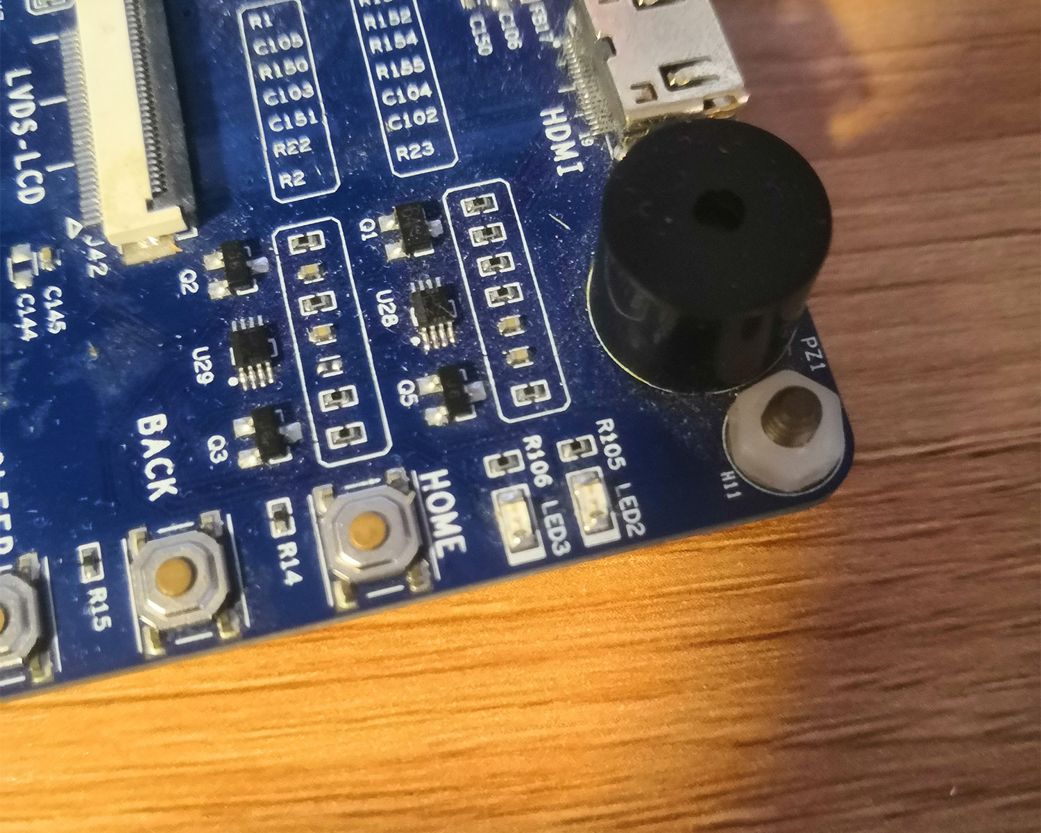
本章要实现的效果是让用户程序控制开发板上LED灯的亮灭。通过查看开发板原理图,得知两个LED灯连的pin脚是gpl2-0和gpk1-1。
(1) 打开pinctrl相关的设备树头文件kernel/arch/arm/boot/dts/exynos4412-pinctrl.dtsi,可以看到gpk和gpl是pinctrl_1的子节点,见下方代码。
...
pinctrl_1: pinctrl@11000000 {
    ...
    gpk1: gpk1 {
          gpio-controller;
          #gpio-cells = <2>;

          interrupt-controller;
          #interrupt-cells = <2>;
    };
    ...
    gpl2: gpl2 {
          gpio-controller;
          #gpio-cells = <2>;

          interrupt-controller;
          #interrupt-cells = <2>;
    };
    ...
}
...
在pinctrl_1节点下添加两个自定义的节点pinctrl_shanwuyan_leds,如下方代码。
pinctrl_1: pinctrl@11000000 {
    ...
    gpk1: gpk1 {
          gpio-controller;
          #gpio-cells = <2>;

          interrupt-controller;
          #interrupt-cells = <2>;
    };
    ...
    gpl2: gpl2 {
          gpio-controller;
          #gpio-cells = <2>;

          interrupt-controller;
          #interrupt-cells = <2>;
    };
    ...
    /*自己添加的设备树节点*/
    pinctrl_shanwuyan_leds: gpio_leds {
          samsung,pins = "gpl2-0","gpk1-1" ;	//LED的pin脚为gpl2-0和gpk1-1
          samsung,pin-function = <EXYNOS_PIN_FUNC_OUTPUT>;	//设置为输出
          samsung,pin-val = <1>;	//默认输出为低电平
          samsung,pin-pud = <EXYNOS_PIN_PULL_UP>;	//设置为上拉
    };
    ...
}
(2) 然后打开设备树文件kernel/arch/arm/boot/dts/exynos4412-itop-elite.dts,在根节点下添加一个自定义节点shanwuyan_leds。另外,如果设备树文件中其他的代码段也使用了这两个pin脚,记得将它们注释掉。本文中,gpk1-1在设备树自带的led灯设备中被使用了,所以要先注释掉。如下方代码。
/ {
    model = "TOPEET iTop 4412 Elite board based on Exynos4412";
    compatible = "topeet,itop4412-elite", "samsung,exynos4412", "samsung,exynos4";

    chosen {
          bootargs = "root=/dev/mmcblk0p2 rw rootfstype=ext4 rootdelay=1 rootwait";
          stdout-path = "serial2:115200n8";
    };

    memory {
          reg = <0x40000000 0x40000000>;
    };
    leds {	//这是设备树自带的led设备节点
          compatible = "gpio-leds";

          led2 {
                label = "red:system";
                gpios = <&gpx1 0 GPIO_ACTIVE_HIGH>;
                default-state = "off";
                linux,default-trigger = "heartbeat";
          };

          led3 {
                label = "red:user";
          //	gpios = <&gpk1 1 GPIO_ACTIVE_HIGH>;	//和我们自己写的led设备所用的pin脚产生了冲突,要注释掉
                default-state = "off";
          };
    };
		...
		...
    /*自己添加的设备树节点*/
    shanwuyan_leds{
          compatible = "samsung,shanwuyan_leds";
          pinctrl-names = "default";
          pinctrl-0 = <&pinctrl_shanwuyan_leds>;
          led-gpios = <&gpl2 0 GPIO_ACTIVE_HIGH>,<&gpk1 1 GPIO_ACTIVE_HIGH>;
          status = "okay";
	};
};
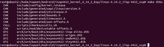
(3) 使用命令make dtbs编译设备树文件。
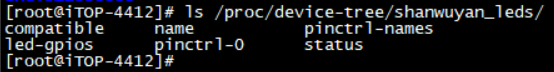
重启开发板,在命令行输入ls /proc/device-tree/shanwuyan_leds/,可以查看到我们新添加的节点及其属性。
3.修改驱动程序
打开驱动代码文件。
(1) 首先添加四个新的头文件,然后把驱动名称修改一下,再添加三个宏定义。如下方代码。
/* 源代码文件名为"shanwuyan.c"*/
#include <linux/module.h>
#include <linux/kernel.h>
#include <linux/init.h>
#include <linux/fs.h>
#include <linux/uaccess.h>
#include <linux/cdev.h>
#include <linux/device.h>

/*新添加如下四个新的头文件*/
#include <linux/of_gpio.h>
#include <linux/gpio.h>
#include <linux/of.h>
#include <linux/io.h>

#define SHANWUYAN_NAME "shanwuyan_leds"	//修改驱动名称
/*添加三个新的宏定义*/
#define LEDS_NUM 2	//LED灯的个数为2
#define LEDS_ON	1	//LED灯的开启状态
#define LEDS_OFF 0	//lED灯的关闭状态
...
(2) 向结构体shanwuyan_dev中添加两个新的成员变量,如下方代码。
struct shanwuyan_dev
{
    struct cdev c_dev;		//字符设备
    dev_t dev_id;			//设备号
    struct class *class;	//类
    struct device *device;	//设备
    int major;				//主设备号
    int minor;				//次设备号

    /*新添加的成员变量*/
    struct device_node *node;	//用于获取设备树节点
    int led_gpios[2];	//用于获取两个led的GPIO编号
};
(3) 我们需要添加一个新的函数leds_init,用以初始化两个LED占用的GPIO。在该函数中,我们使用GPIO子系统提供的API函数,对pin脚进行操作。在添加之前,我们要先介绍几个函数。
//位于linux/of.h文件中
static inline struct device_node *of_find_node_by_path(const char *path);
//通过节点路径来查找设备树节点,若查找失败,则返回NULL
//位于linux/of_gpio.h文件中
static inline int of_get_named_gpio(struct device_node *np, const char *propname, int index);
//通过设备树节点、属性名、属性索引号来获取GPIO编号,若获取失败,则返回一个负数
//位于linux/gpio.h文件中
static inline int gpio_request(unsigned gpio, const char *label);
//申请GPIO,第一个参数是GPIO编号,第二个参数是给GPIO加的标签(由程序员给定),如果申请成功,则返回0,否则返回一个非零数
static inline void gpio_free(unsigned gpio);
//释放GPIO,参数是GPIO编号
static inline int gpio_direction_input(unsigned gpio);
//把GPIO设置为输入模式,参数是GPIO编号,如果设置成功,则返回0,否则返回一个非零数
static inline int gpio_direction_output(unsigned gpio, int value);
//把GPIO设置为输出模式,第一个参数是GPIO编号,第二个参数是默认输出值,如果设置成功,则返回0,否则返回一个非零数
static inline void gpio_set_value(unsigned int gpio, int value);
//设置GPIO的输出值,第一个参数是GPIO编号,第二个参数是输出值
接下来我们添加函数led_init,然后在入口函数shanwuyan_init中调用它,在加载驱动的时候就完成GPIO的初始化。相应的,在出口函数shanwuyan_exit中,要释放掉申请的GPIO。如下方代码。
...
static int leds_init(struct shanwuyan_dev *leds_dev)//初始化led的GPIO
{
    int ret = 0;
    int i = 0;
    char led_labels[][20] = {"led_gpio_0", "led_gpio_1"};	//定义两个设备标签

    /*1.根据设备节点在设备树中的路径,获取设备树中的设备节点*/
    leds_dev->node = of_find_node_by_path("/shanwuyan_leds");
    if(leds_dev->node == NULL)
    {
          ret = -EINVAL;
          printk("cannot find node /shanwuyan_leds\r\n");
          goto fail_find_node;
    }

    /*2.获取led对应的gpio*/
    for(i = 0; i < LEDS_NUM; i++)
    {
          leds_dev->led_gpios[i] = of_get_named_gpio(leds_dev->node, "led-gpios", i);
          if(leds_dev->led_gpios[i] < 0)	//如果获取失败
          {
                printk("cannot get led_gpio_%d\r\n", i);
                ret = -EINVAL;
                goto fail_get_gpio;
          }
    }
    for(i = 0; i < LEDS_NUM; i++)	//打印出获取的gpio编号
          printk("led_gpio_%d = %d\r\n", i, leds_dev->led_gpios[i]);

    /*3.申请gpio*/
    for(i = 0; i < LEDS_NUM; i++)
    {
          ret = gpio_request(leds_dev->led_gpios[i], led_labels[i]);
          if(ret)	//如果申请失败
          {
                printk("cannot request the led_gpio_%d\r\n", i);
                ret = -EINVAL;
                if(i == 1)
                      goto fail_request_gpio_1;
                else
                      goto fail_request_gpio_0;
          }
    }


    /*4.使用gpio:设置为输出*/
    for(i = 0; i < LEDS_NUM; i++)
    {
          ret = gpio_direction_output(leds_dev->led_gpios[i], 1);
          if(ret)	//如果是指失败
          {
                printk("failed to set led_gpio_%d\r\n", i);
                ret = -EINVAL;
                goto fail_set_output;
          }
    }

    /*5.设置输出高电平,led会亮*/
    for(i = 0; i < LEDS_NUM; i++)
          gpio_set_value(leds_dev->led_gpios[i], 1);

    return 0;

fail_set_output:
    gpio_free(leds_dev->led_gpios[1]);	//释放掉led_gpio_1
fail_request_gpio_1:
    gpio_free(leds_dev->led_gpios[0]);//如果led_gpio_1申请失败,则也要把led_gpio_0也要释放掉
fail_request_gpio_0:
fail_get_gpio:
fail_find_node:
	return ret;
}

static int __init shanwuyan_init(void)	//驱动入口函数
{
    int ret = 0;

    /*1.分配设备号*/
    ...

    /*2.向内核添加字符设备*/
    ...

    /*3.自动创建设备节点*/
    ...

    /*4.初始化GPIO*/
    leds_init(&shanwuyan);

    return 0;
}

static void __exit shanwuyan_exit(void)	//驱动出口函数
{
    int i = 0;
    /*释放GPIO*/
    for(i = 0; i < LEDS_NUM; i++)
          gpio_free(shanwuyan.led_gpios[i]);
    /*注销设备号*/
    ...
    /*摧毁设备*/
    ...
    /*摧毁类*/
    ...
}
...
(4) 然后一下open函数,因为该函数有一个参数我们一直没有使用,现在我们使用它,close函数无需改造。如下方代码。
...
/*打开设备*/
static int shanwuyan_open(struct inode *inode, struct file *filp)
{
    printk(KERN_EMERG "shanwuyan_open\r\n");
    filp->private_data = &shanwuyan;	//在设备操作集中,我们尽量使用私有数据来操作对象
    return 0;
}
...
(5) 最后改造write函数(用户程序控制GPIO,只需要用到write函数,用不到read函数,所以不用改造read函数)。如下方代码。
...
/*写设备*/
static ssize_t shanwuyan_write(struct file *filp, const char __user *buf, size_t count, loff_t *ppos)
{
    int i = 0;
    int ret = 0;
    char user_data;	//保存用户数据

    struct shanwuyan_dev *led_dev = filp->private_data;	//获取私有变量

    ret = copy_from_user(&user_data, buf, count);	//获取用户数据
    if(ret < 0)
          return -EINVAL;

    if(user_data == LEDS_ON)	//如果接到的命令是打开LED
          for(i = 0; i < LEDS_NUM; i++)
                gpio_set_value(led_dev->led_gpios[i], LEDS_ON);
    else if(user_data == LEDS_OFF)	//如果接到的命令是关闭LED
          for(i = 0; i < LEDS_NUM; i++)
                gpio_set_value(led_dev->led_gpios[i], LEDS_OFF);

    return 0;
}
...
4.修改用户程序
用户程序只用得到写操作,可以把读操作的代码删除。再另外修改一下写操作的代码,如下。
//源代码名称为 "shanwuyanAPP.c"
#include <sys/types.h>
#include <sys/stat.h>
#include <fcntl.h>
#include <stdio.h>
#include <unistd.h>
#include <stdlib.h>
#include <string.h>

/*
*argc:应用程序参数个数,包括应用程序本身
*argv[]:具体的参数内容,字符串形式
*./shanwuyanAPP <filename> <0:1> 0表示LED灭,1表示LED亮
*/
int main(int argc, char *argv[])
{
    int ret = 0;
    int fd = 0;
    char *filename;

    char user_data;

    user_data = atoi(argv[2]);

    if(argc != 3)
    {
          printf("Error usage!\r\n");
          return -1;
    }

    filename = argv[1];	//获取设备名称

    fd = open(filename, O_RDWR);
    if(fd < 0)
    {
          printf("cannot open device %s\r\n", filename);
          return -1;
    }

    /*写操作*/
    ret = write(fd, &user_data, sizeof(char));
    if(ret < 0)
          printf("write error!\r\n");

    /*关闭操作*/
    ret = close(fd);
    if(ret < 0)
    {
          printf("close device %s failed\r\n", filename);
    }

    return 0;
}
5.应用
编译驱动,交叉编译用户程序,拷贝到开发板中。
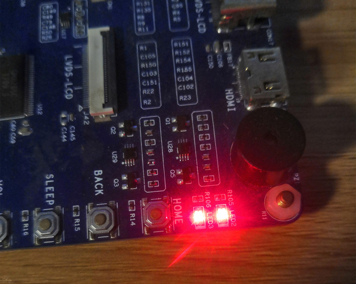
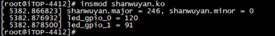
加载驱动,可以看到开发板上的LED灯亮了起来。
同时可以在终端看到两个LED的GPIO编号。
在终端输入命令./shanwuyanAPP /dev/shanwuyan_leds 0,可以看到两个LED灯灭掉。
再在终端输入命令./shanwuyanAPP /dev/shanwuyan_leds 1,可以看到两个LED灯又亮起来。

本文全部代码在这里

 浙公网安备 33010602011771号