
Controlling a Digital Potentiometer Using SPI
In this tutorial you will learn how to control the AD5206 digital potentiometer(数字电位计) using Serial Peripheral Interface (SPI). For an explanation of SPI see the SPI Library reference.
Digital potentiometers are useful when you need to vary the resistance in a circuit electronically rather than by hand. Example applications include LED dimming调光, audio signal conditioning and tone generation. In this example we will use a six channel digital potentiometer to control the brightness of six LEDs. The steps we will cover for implementing实施 SPI communication can be modified for use with most other SPI devices.
Hardware Required 硬件准备
- Arduino or Genuino board
- AD5206 Digital Potentiometer
- 6 LEDs
- 6 220 ohm resistors
- hook-up wires电子安装线
- breadboard
Introduction to the AD5206 Digital Potentiometer
Click for for the AD5206's datasheet.
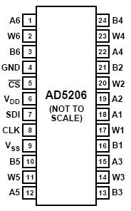
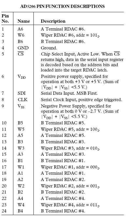
The AD5206 is a 6 channel digital potentiometer. (AD5206是8通道的数字电位器)。 This means it has six variable resistors (potentiometers) built in for individual electronic control. There are three pins on the chip for each of the six internal variable resistors, and they can be interfaced with just as you would use a mechanical potentiometer. The individual variable resistor pins are labeled Ax, Bx and Wx, ie. A1, B1 and W1. For example, in this tutorial we will be using each variable resistor as a voltage divider by pulling one side pin (pin B) high, pulling another side pin (pin A) low and taking the variable voltage output of the center pin (Wiper滑片). In this case, the AD5206 provides a maximum resistance of 10k ohm, delivered in 255 steps (255 being the max, 0 being the least).(可以得到最大电阻10K欧姆,最小0欧模,分为255步幅)
Circuit 电路图
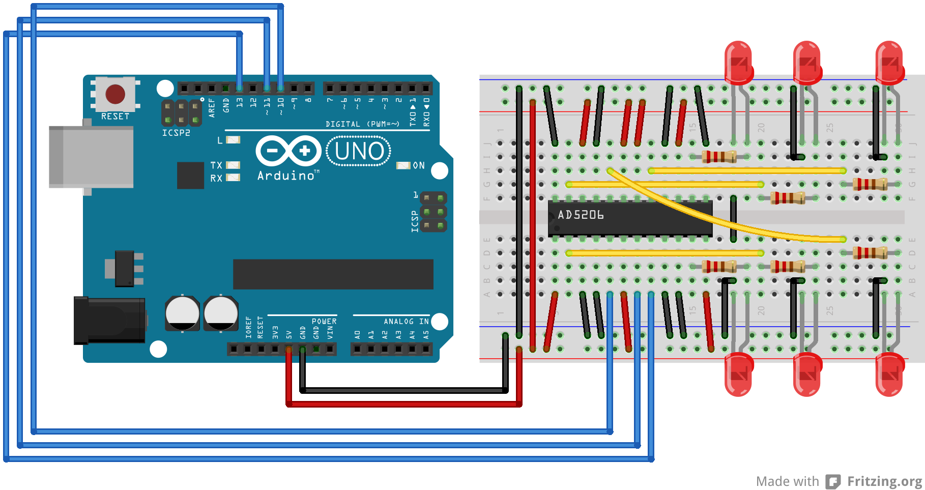
image developed using Fritzing. For more circuit examples, see the Fritzing project page
Schematic 原理图

  1 Code 代码
  2
  3 /*
  4
  5   Digital Pot Control 数字电位器的控制
  6
  7
  8
  9   This example controls an Analog Devices AD5206 digital potentiometer.
 10
 11   The AD5206 has 6 potentiometer channels. Each channel's pins are labeled
 12
 13   A - connect this to voltage
 14
 15   W - this is the pot's wiper, which changes when you set it
 16
 17   B - connect this to ground.
 18
 19 每隔通道有三个端,A,B,W,A接工作电压,W接滑动端,C接地
 20
 21  The AD5206 is SPI-compatible, and to command it, you send two bytes, one with the channel number (0 - 5) and one with the resistance value for the channel (0 - 255).
 22
 23
 24
 25  The circuit:
 26
 27   * All A pins of AD5206 connected to +5V
 28
 29   * All B pins of AD5206 connected to ground
 30
 31   * An LED and a 220-ohm resisor in series connected from each W pin to ground
 32
 33 每个W引脚的LED串220欧电阻
 34
 35   * CS - to digital pin 10  (SS pin)    片选引脚CS接到控制板的引脚10
 36
 37   * SDI - to digital pin 11 (MOSI pin)   SDI引脚接到控制板的引脚11
 38
 39   * CLK - to digital pin 13 (SCK pin)    CLK 引脚接到控制板的引脚13
 40
 41
 42
 43  created 10 Aug 2010
 44
 45  by Tom Igoe
 46
 47
 48  Thanks to Heather Dewey-Hagborg for the original tutorial, 2005
 49
 50
 51
 52 */
 53
 54
 55
 56 // inslude the SPI library:
 57
 58 #include <SPI.h>
 59
 60
 61
 62 // set pin 10 as the slave select for the digital pot:
 63
 64 const int slaveSelectPin = 10;  // 从选择引脚
 65
 66
 67
 68 void setup()
 69
 70 {
 71
 72   pinMode(slaveSelectPin, OUTPUT);   // set the slaveSelectPin as an output
 73
 74   SPI.begin();    // initialize SPI
 75
 76 }
 77
 78
 79
 80 void loop()
 81
 82 {
 83
 84   // go through the six channels of the digital pot:   循环数字电位器的六个通道
 85
 86   for (int channel = 0; channel < 6; channel++)
 87
 88 {
 89
 90     // change the resistance on this channel from min to max:   电阻从小到大
 91
 92 for (int level = 0; level < 255; level++)
 93
 94 {
 95
 96       digitalPotWrite(channel, level);
 97
 98       delay(10);
 99
100 }
101
102     delay(100);   // wait a second at the top
103
104     // change the resistance on this channel from max to min:  电阻从大到小
105
106 for (int level = 0; level < 255; level++)
107
108 {
109
110       digitalPotWrite(channel, 255 - level);
111
112       delay(10);
113
114 }
115
116 }
117
118 }
119
120
121
122 void digitalPotWrite(int address, int value)
123
124 {
125
126   // take the SS pin low to select the chip:    SS引脚置低选中该芯片
127
128   digitalWrite(slaveSelectPin, LOW);
129
130   //  send in the address and value via SPI:
131
132   SPI.transfer(address);  //传送地址
133
134   SPI.transfer(value);    //传送数值
135
136   // take the SS pin high to de-select the chip:  SS引脚置高释放该芯片
137
138   digitalWrite(slaveSelectPin, HIGH);
139
140 }
运行效果:从第1通道开始,每个通道的LED,从最暗到最亮,0.1秒后,再从最亮到最暗。
