

【ANSYS 学习笔记】Case05_Basic Transient Sources and Circuit
• Transient Setup
– This workshop discusses basic setup details of 2D Magnetic Transient solver
–本研讨会讨论2D电磁瞬态求解器的基本设置细节
– The transient setup is described with two different excitation methods
–用两种不同的激励方法描述了瞬态设置
Example 1: Transient With Sources
– This example shows setup of 2D Transient solver with time varying excitation applied through datasets and equation.
– Final assigned excitation is evaluated based on combined output of both methods
–此示例显示了2D瞬态求解器的设置,其中通过数据集和方程式应用了随时间变化的激励。
–基于两种方法的组合输出评估最终分配的激励
【Step01 建立设计文档】
• Create Design
– Select the menu item Project Insert Maxwell 2D Design, – Change the name of the Design to BE_Trans_Sources
• Set the Solution Type:
– Select the menu item Maxwell 2D Solution Type
– Solution Type Window:
1. Geometry Mode: Cylindrical about Z
2. Choose Magnetic > Transient
3. Click the OK button

【Step02:Create Model 建立模型】
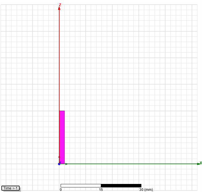
• Create Core
– Select the menu item Draw Rectangle
1. Using the coordinate entry fields, enter the position of rectangle
– X: 0, Y: 0, Z: 0, Press the Enter key
2. Using the coordinate entry fields, enter the opposite corner
– dX: 2, dY: 0, dZ: 20, Press the Enter key
– Change the name of resulting sheet to Core and color to green
– Change the material of the sheet to Ferrite
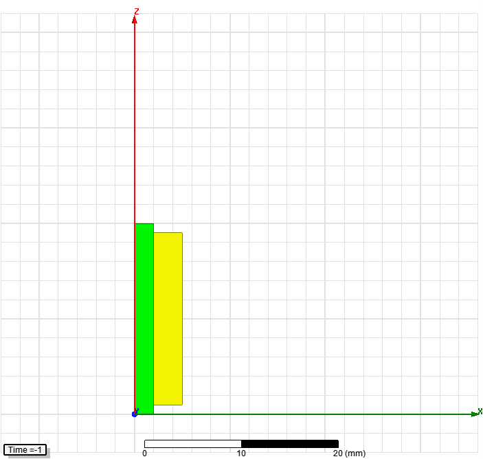
• Create Coil
– Select the menu item Draw Rectangle
1. Using the coordinate entry fields, enter the position of rectangle
– X: 0, Y: 0, Z: 1, Press the Enter key
2. Using the coordinate entry fields, enter the opposite corner
– dX: 5, dY: 0, dZ: 18, Press the Enter key
– Change the name of resulting sheet to Coil and color to Yellow
– Change the material of the sheet to Copper

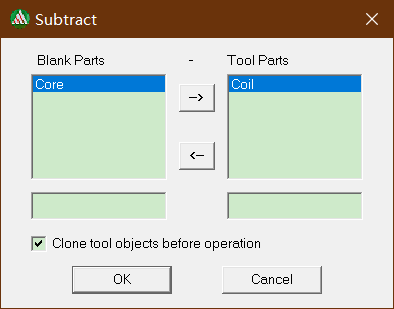
• Subtract Sheets
– Press Ctrl and select the sheets Core and Coil
– Select the menu item Modeler Boolean Subtract
• Blank Part: Coil
• Tool Part: Core
• Clone tool objects before subtracting: checked
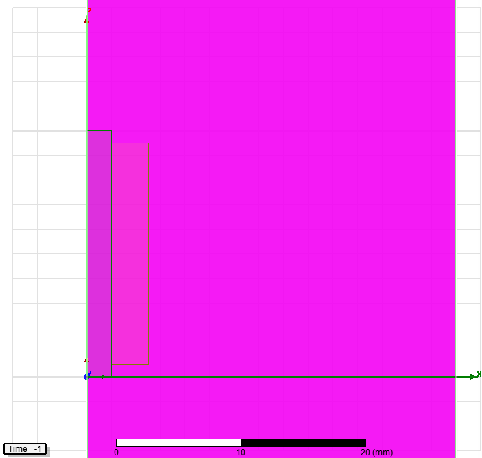
• Create Simulation Region
– Select the menu item Draw Region
– In Region window,
1. Pad all directions similarly: Checked
2. Padding Type: Percentage Offset
3. Value: 500
4. Press OK

【Step03 Assign Excitation 创建激励】
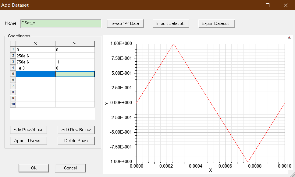
Note: The excitation for this problem will be a voltage source with a 1KHz triangular wave superimposed on a 50 Hz sine wave that has a 50 volt DC offset. Triangular wave will be specified through a design dataset.
注意:此问题的激发将是一个电压源,该电压源具有一个1KHz三角波,该三角波叠加在具有50伏DC偏移的50 Hz正弦波上。 将通过设计数据集指定三角波。
• Specify Dataset
– Select the menu item Maxwell 2D Design Datasets
– In Datasets window, select Add
– In Add Dataset window,
• Name: DSet_A
• Coordinates:
1. X1 = 0 Y1 = 0
2. X2 = 250e-6 Y2 = 1
3. X3 = 750e-6 Y3 = -1
4. X4 = 1e-3 Y4 = 0
• Select OK and Done
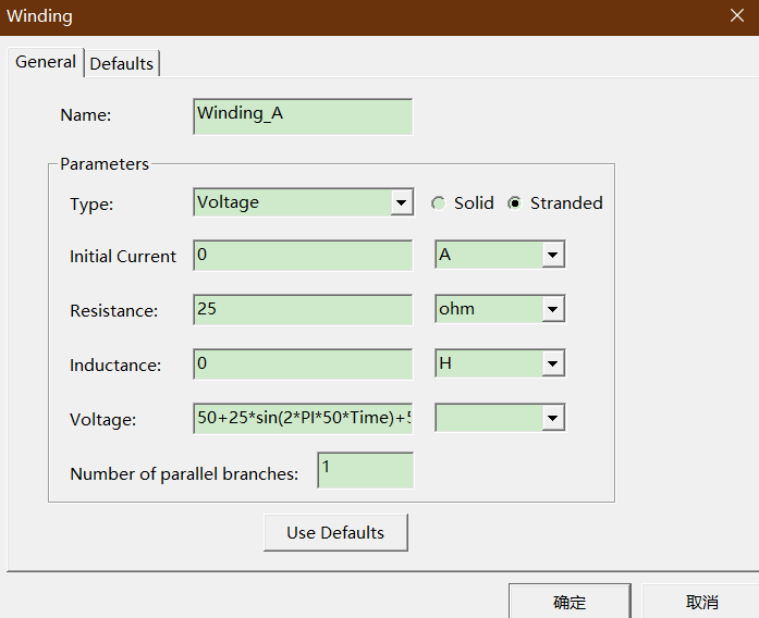
• Add Winding
– Select the menu item Maxwell 2D Excitations Add Winding
– In Winding window,
1. Name: Winding_A
2. Type: Voltage
3. Stranded: Checked
4. Initial Current: 0 A
5. Resistance: 25 ohm
6. Inductance: 0 H
7. Voltage: 50 + 25*sin(2*PI*50*Time) + 5*pwl_periodic(DSet_A, Time)
8. Press OK
Note: The expression specified for Voltage has three different components
1. The first term is a 50 V DC offset
2. The second term is a 25 Vp-p, 50 Hz sine wave
3. The third term is a 5 Vp-p, 1 KHz triangular wave
Final applied voltage will be combined output of all three components
注意:为电压指定的表达式具有三个不同的成分
第一项是50 V DC偏移
2.第二项是25 Vp-p,50 Hz正弦波
3.第三项是5 Vp-p,1 KHz三角波
最终施加的电压将是所有三个组件的组合输出
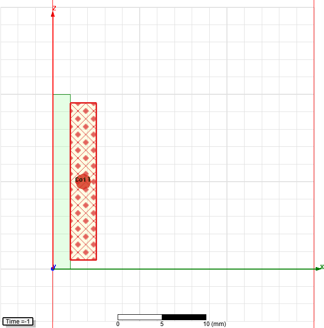
• Create Coil
– Select the object Coil from history tree
– Select the menu item Maxwell 2D Excitations Assign Coil
• Name: Coil
• Number of Conductors: 150
• Polarity: Positive (into the screen)
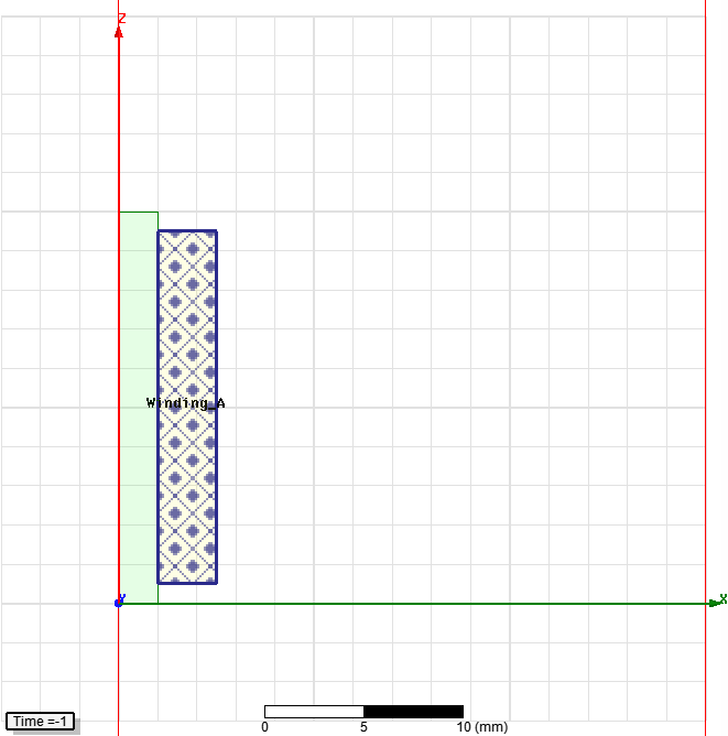
• Add Coil to Winding
– Expand the Project Manager tree to view Excitations
– Right click on the tab Winding_A and select Add Coils
– In Add Terminals window,
• Select Coil
• Press OK
【Step04 Assign Boundary创建边界】
• Assign Balloon Boundary
– Select the object Region from history tree
– Select the menu item Edit Select All Object Edges
– Select the menu item Maxwell 2D Boundaries Assign Balloon
– In Balloon Boundary window,
• Press OK
Note: On symmetry axis, "Balloon Boundary" assignment is automatically skipped, This can also be achieved by selecting the edges of region which are not on symmetry axis
注意:在对称轴上,将自动跳过"气球边界"分配,这也可以通过选择不在对称轴上的区域的边缘来实现
【Step05 Assign Mesh Operations 分配网格操作】
Note: A transient solver does not use the adaptive meshing technique. Thus manual mesh specifications are required to refine the mesh in important regions to achieve accuracy of results.
注意:瞬态求解器不使用自适应网格划分技术。 因此,需要手动的网格规范来完善重要区域中的网格以实现结果的准确性。
• Assign Mesh Operation for Core
– Select the object Core from history tree
– Select the menu item Maxwell 2D Mesh Operations Assign Inside
Selection Length Based
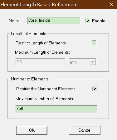
– In Element Length Based Refinement window,
• Name: Core_Inside
• Restrict Length Of Elements: Unchecked
• Restrict Number of Elements: Checked
• Maximum Number of Elements: 250
• Press OK
• Assign Mesh Operation for Coil
– Select the object Coil from history tree
– Select the menu item Maxwell 2D Mesh Operations Assign Inside
Selection Length Based
– In Element Length Based Refinement window,
• Name: Coil_Inside
• Restrict Length Of Elements: Unchecked
• Restrict Number of Elements: Checked
• Maximum Number of Elements: 100
• Press OK
【Step06 Analyze 分析】
• Create Analysis Setup
– Select the menu item Maxwell 2D Analysis Setup Add Solution Setup
– In Solve Setup window,
• General tab
– Stop Time: 20 ms
– Time Step: 100 us
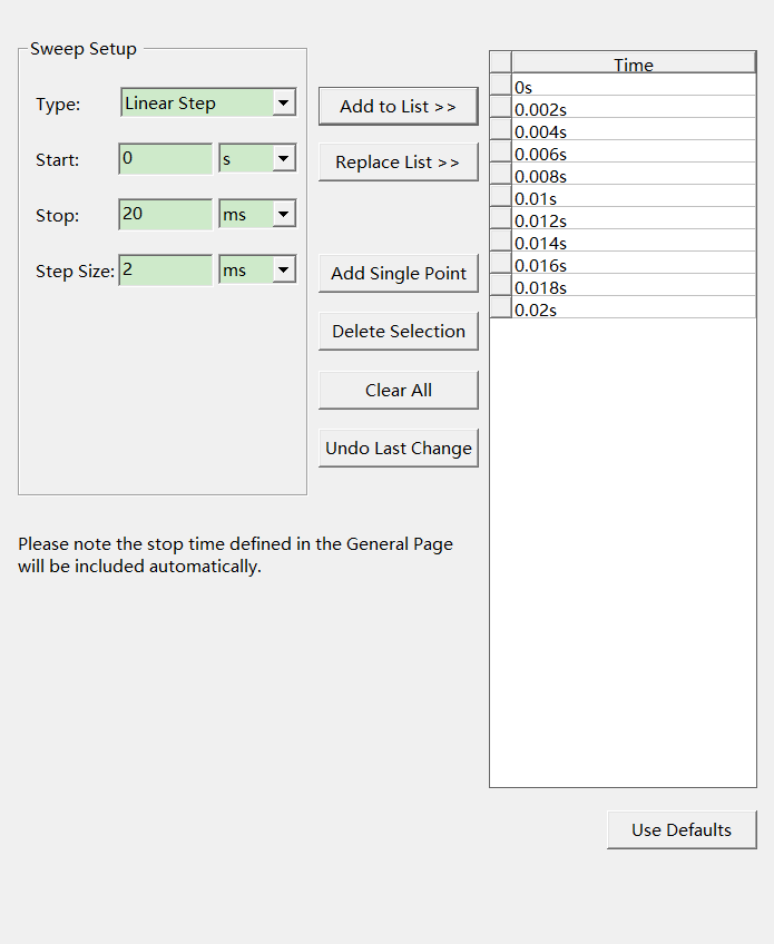
• Save Fields Tab
– Type: Linear Count
– Start: 0 sec
– Stop: 20 ms
– Step Size: 2 ms
– Click on: Add to List
• Press OK
• Run Solution
– Select the menu item Maxwell 2D Analyze All
【Step07 绘制电压电流波形】
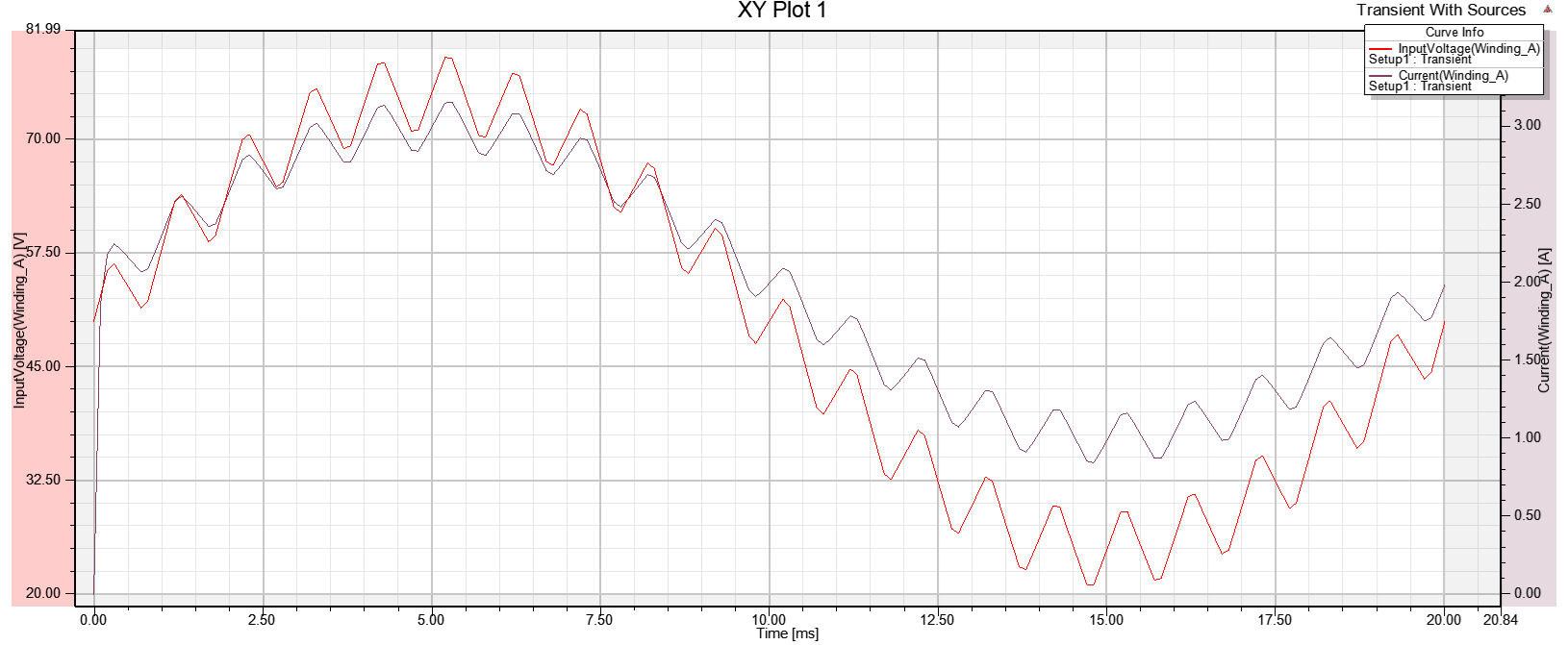
• Create a Plot
– Select the menu item Maxwell 2D Results Create Transient Report
Rectangular plot
1. In Reports window, Category: Winding
2. Quantity: InputVoltage(Winding_A)
3. Select New Report
4. Change Quantity to Current(Winding_A)
5. Select Add Trace
6. Press Close
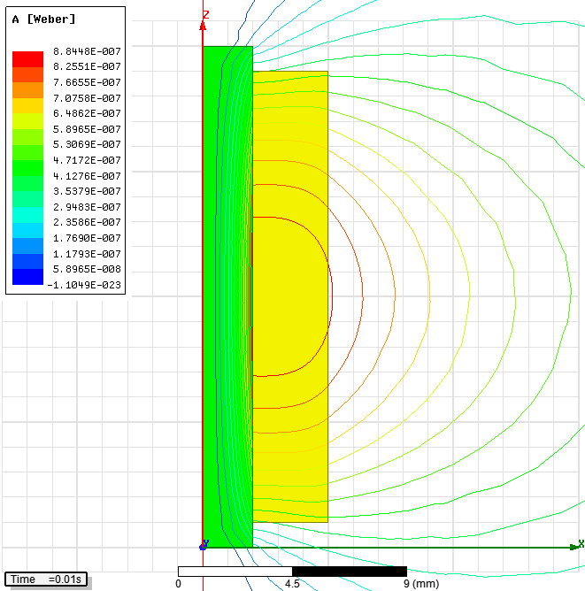
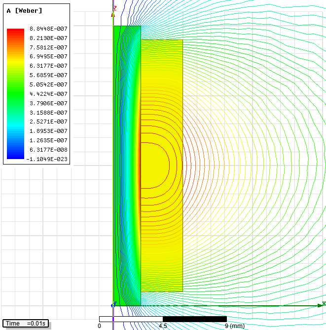
• Plot Flux Lines
– Be sure that the 2D Modeler window is in the active view window.
– Select the menu item View Set Solution Context
– In Set view Context window,
• Time: Set to 0.01 sec
• Press OK

– Select the menu Edit Select All
– Select the menu item Maxwell 2D Fields Fields A Flux_Lines
– In Create Field Plots window, Press Done
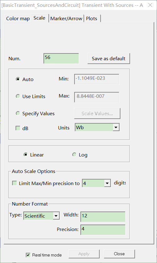
• Modify Plot
– Double click on the legend to modify its attributes
– In the window,
• Scale tab
– Num. Divisions: 56
• Press Apply and Close
Exampled 2: Transient With Circuits
– This example explains the setup of transient excitations through External Circuit method.
本示例说明了通过外部电路方法设置瞬态激励的方法。
– The excitation circuit is setup using Maxwell Circuit Editor
使用Maxwell Circuit Editor设置激励电路
– Maxwell excitation values are calculated based on the circuit model assigned through circuit editor
麦克斯韦励磁值是根据通过电路编辑器分配的电路模型计算得出的
【Step01 创建设计】
• Copy Design
– Select the design "BE_Trans_Sources" from Project manager tree.
– Right click and select Copy
– Select the name of the project from Project Manager tree
– Right click on it and select Paste
– Rename the new design as "BE_Trans_Circuit"
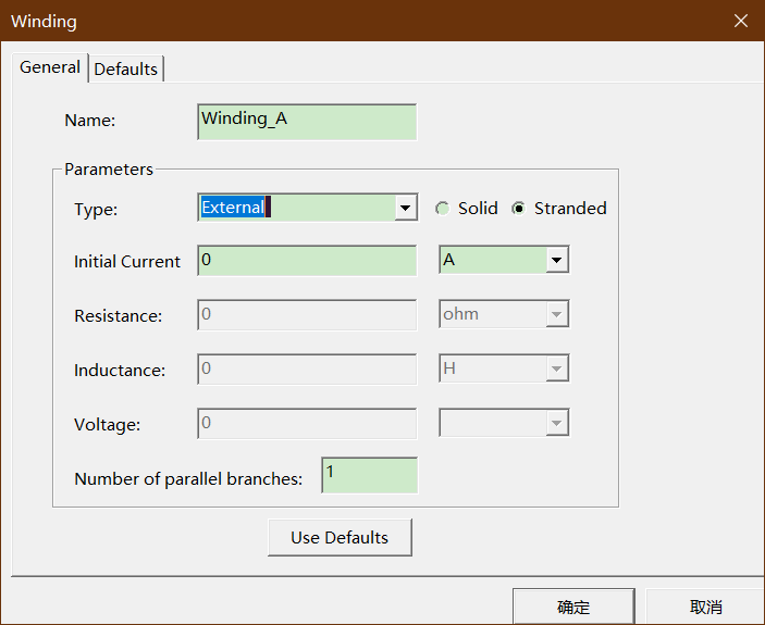
• Modify Winding Setup
– Expand the Project Manager tree to view Excitations
– Double click on Winding_A under Excitations
– Change the Type to External
– Press OK
【Step02 Create External Circuit 创建外部电路】
• Launch Maxwell Circuit Editor
– Select the menu item Maxwell 2D Excitations External Circuit Edit
External Circuit
– In Edit External Circuit window,
• Select Edit Circuit
– Maxwell Circuit Editor will launch in separate window
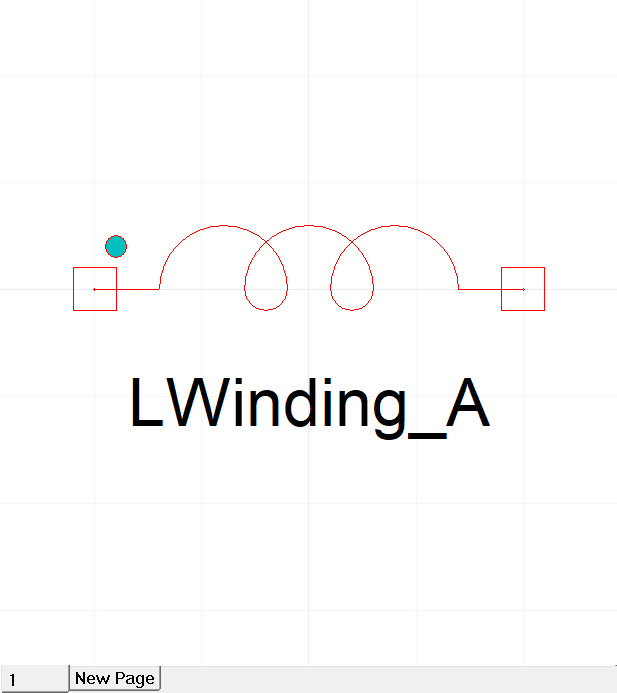
In Maxwell Circuit Editor a Component is created by default corresponding to winding in Maxwell. The name of the winding is same as as used in Maxwell in Maxwell 3D > Excitations > Add Winding. If users add winding by themselves they should ensure these names match
在Maxwell Circuit Editor中,默认情况下会创建一个与Maxwell中的绕组相对应的组件。 绕组的名称与Maxwell 3D>激励>添加绕组中的Maxwell中使用的名称相同。 如果用户自己添加绕组,则应确保这些名称匹配
• Add Source Components
– Change the tab in Project Manager window to Components
– In Project Manager window, expand the tree for Maxwell Circuit Elements >
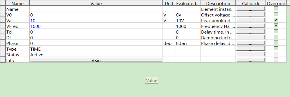
Sources. Select the element Vsin from the tree, drag and drop it on the
worksheet.
– Press Esc to exit component insertion
– Double click on the component to modify its properties
1. Change the value of Va to 100 V
2. Change the value of VFreq to 50 Hz

– Similarly add another source Vsin
1. Change the value of Va to 10 V
2. Change the value of VFreq to 1000 Hz
• Add Other Components
– Similarly add Passive Elements > Res
1. Change the value of R to 25 ohm
– Add Probes > Voltmeter
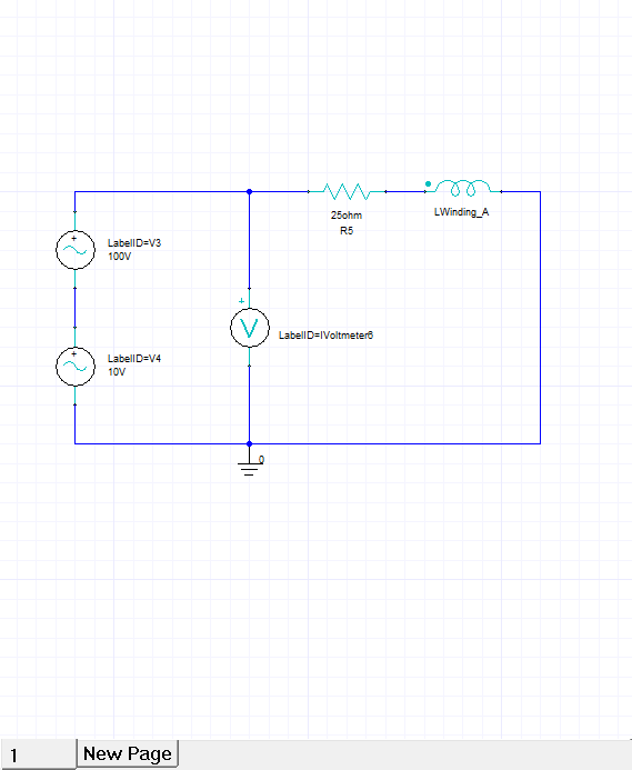
• Build Circuit
– Select the menu item Draw Wire to draw wires
– Select the menu item Draw Ground to add ground
– Build the circuit as shown in image
【Step03 Transfer Circuit to the Maxwell 】
• Save File
– Select the menu item File Save
1. Save the file with the name WS5_BasicTransient_Circuit.amcp
• Export Circuit
– Select the menu item Maxwell Circuit Export Netlist
1. Save the file with the name WS5_BasicTransient_Circuit.sph
• Import circuit in Maxwell
– Return to Maxwell window
– In Edit External Circuit window,
1. Select Cancel
2. Select the tab Import Circuit
3. Browse to file WS5_BasicTransient_Circuit.sph
4. Select the file and press OK
【Step04 Analyze 分析 】
• Run Solution
– Solution setup is already copied from original design
– Select the menu item Maxwell 3D Analyze All
Note: When an external circuit is defined, the time step is controlled from the circuit simulator. The time step values are calculated based circuit transients and occurrences such as switching instances. Due to variable time steps resulting from circuit, Maxwell can miss the Save Fields points if defined in Solution Setup. Thus fields of the next time step occurring after the missed point will be saved.
Users can set the minimum time step size used for circuit simulator from
Maxwell 3D Excitations External Circuit Set Minimum Time Step
注意:定义了外部电路后,时间步长可通过电路模拟器控制。 该时间步长值是根据电路瞬变和发生情况(例如开关实例)来计算的。 由于电路产生的时间步长可变,如果在"解决方案设置"中定义,Maxwell可能会错过"保存字段"点。 因此,将保存在错过点之后发生的下一个时间步的字段。
用户可以从以下位置设置用于电路模拟器的最小时间步长
Maxwell 3D Excitations External Circuit Set Minimum
【Step05:绘图输出】
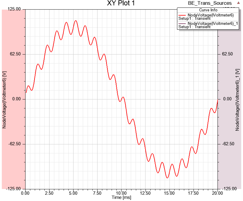
• Plot the Voltage and Current
– Plots from previous design will still be there. But Voltage plot has no reference
since Input voltage is not applied but received from circuit
– Double click on the plot from Project manager tree
1. Change Category to NodeVoltage
2. Quantity: NodeVoltage
3. Select Apply Trace
– To View Results better, double click on Y Axis corresponding to NodeVoltage and
change its range to -150 to 150 V
• Plot Flux Lines
– Select the menu item View Set Solution Context
– In Set view Context window,
• Time: Set to 0.01 sec
• Press OK
– Flux Lines plot is copied with the design.
– Double click on the plot to view the results


 浙公网安备 33010602011771号