

【ANSYS 学习笔记】Case04_Basic DC Conduction Analysis
• DC Conduction Solver
– This workshop introduces the DC conduction solver. Only conductors are considered in the process i.e. without including insulator fields.
介绍了直流传导求解器。 在该过程中仅考虑导体,即不包括绝缘体场
Example 1 : Parallel Plates with Non-uniform media in XY Plane
• In this example, we want to determine the DC resistance between two plates with a non-uniform media made of graphite and sea water. The Problem is solved with 2D XY representation.
在此示例中,我们要确定使用石墨和海水制成的非均匀介质的两块板之间的直流电阻。 通过2D XY表示解决了问题。
【Step01:建立工程文档,并设置基本参数】
• Create Design
– Select the menu item Project Insert Maxwell 2D Design
– Change the name of the design to Plates
• Set Solution Type
– Select the menu item Maxwell 2D Solution Type
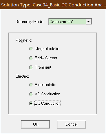
– Solution Type Window:
1. Geometry Mode: Cartesian, XY
2. Choose DC Conduction
3. Click the OK button
【Step02:Create Geometry 创建几何体】
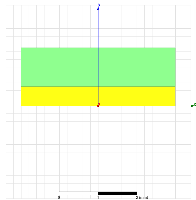
• Create Solid 创建实体
– Select the menu item Draw Rectangle
1. Using the coordinate entry fields, enter the box position
– X: -2, Y: 0, Z: 0, Press the Enter key
2. Using the coordinate entry fields, enter the opposite corner
– dX: 4, dY: 0.5, dZ: 0, Press the Enter key
– Change the name of the sheet to Solid and material to graphite 石墨材料

• Create Liquid 创建液体模型
– Select the menu item Draw Rectangle
1. Using the coordinate entry fields, enter the box position
– X: -2, Y: 0.5, Z: 0, Press the Enter key
2. Using the coordinate entry fields, enter the opposite corner
– dX: 4, dY: 1, dZ: 0, Press the Enter key
– Change the name of the sheet to Liquid and material to water_sea
【Step03:Assign Excitations 分配激励】
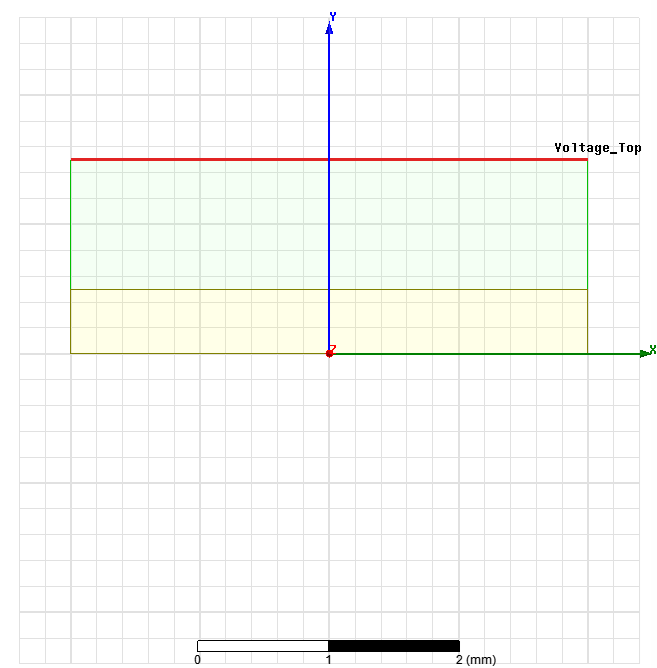
• Assign Excitation for Top
– Select the menu item Edit Select Edges or press E from the keyboard
– Select the top edge of the sheet Liquid
– Select the menu item Maxwell 2D Excitations Assign Voltage
– In Voltage Excitation window,
1. Set Value to 10 V
2. Press OK
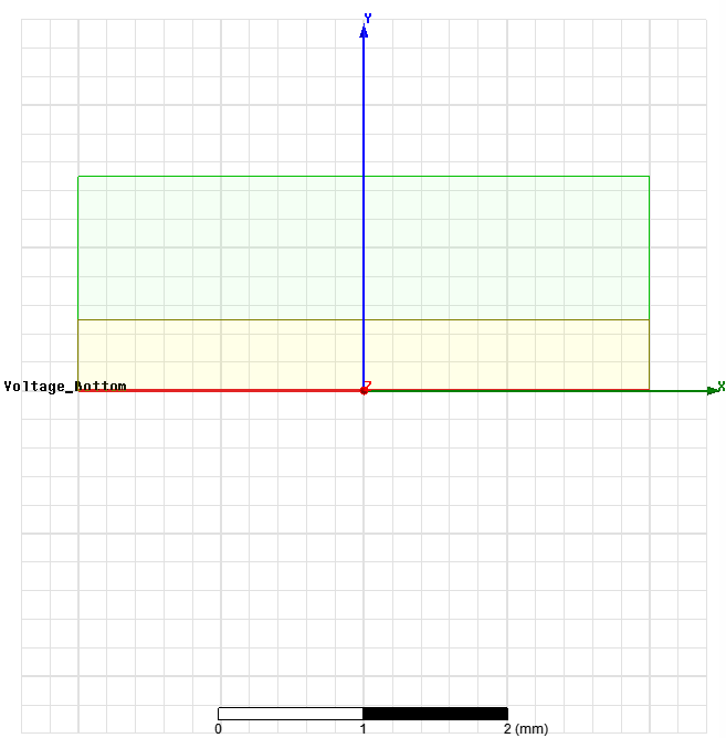
• Assign Excitation for Bottom
– Select the bottom edge of the sheet Solid
– Select the menu item Maxwell 2D Excitations Assign Voltage
– In Voltage Excitation window,
1. Set Value to -10 V
2. Press OK
【Step04:Analyze 创建分析】
• Create an analysis setup:
– Select the menu item Maxwell 2D Analysis Setup Add Solution Setup
– Solution Setup Window:
1. Click the OK to accept default settings
• Start the solution process:
– Select the menu item Maxwell 2D Analyze All
【Step05:Compute the DC Resistance 计算直流电阻】
Note: DC Resistance is not calculated automatically by Maxwell. But since we already know the voltages applied, Resistance can be calculated. We need the DC current that flows through the media. The current is obtained by taking the integral of Y component of J on a cross section of the region. To define any cross section, we will create a line at the middle of Liquid. The total current going through the media is the integral of the current J on the this line multiplied by depth of the model in Z direction
注意:Maxwell不会自动计算直流电阻。 但是由于我们已经知道所施加的电压,因此可以计算出电阻。 我们需要流经介质的直流电流。 通过对该区域的横截面取J的Y分量的积分来获得电流。 要定义任何横截面,我们将在Liquid的中间创建一条线。 流经介质的总电流是该线上电流J的积分乘以模型在Z方向上的深度
• Create Line
– Select the menu item Draw Line
• A massage will pop up asking if the geometry needs to be created as a nonmodel object, press Yes
1. Using the coordinate entry fields, enter the first point
– X: -2, Y: 1, Z: 0, Press the Enter key
2. Using the coordinate entry fields, enter the second point
– X: 2, Y: 1, Z: 0, Press the Enter key
3. Press Enter again to exit the drawing
– Change the name of the line to Sec_Line

• Calculate Resistance
– Select the menu item Maxwell 2D Fields Calculator
– In Field Calculator window,
1. Select Input > Quantity > J
2. Select Vector > Scal? > ScalarY
3. Select Input > Geometry
– Select Line > Sec_Line > Press OK
4. Select Scalar > Integrate
5. Press Eval

– The reported value is around -320. The total current appears, close to 1.28A(-320*0.004) assuming dimensions of the plates in Z is 4mm.The value is very low; it makes sense because the conductivity of medium is very low. The negative sign is just a matter of sign convention due to the CS orientation.
–计算出来的值约为-320。 假设Z板的尺寸为4mm,则出现总电流,接近1.28A(-320 * 0.004)。 这是有道理的,因为介质的电导率非常低。 由于CS方向的原因,负号只是符号约定的问题。
– The DC resistance is given by R = Voltage / Current. The difference of potential between the two plate is 20 V. We obtain R = 15.625 Ohm
–直流电阻由R =电压/电流给出。 两块极板之间的电位差为20V。我们得到R = 15.625 Ohm
• Analytical value of Resistance
– The analytical value of the resistance is given by the following formula
R = σ2h1 + σ1h2 / ( σ1σ2A)
where σ1, σ2 are the conductivity of the two medium, h1,h2 the thickness of the two medium and A the surface of the plates.
– If we take below values,
• σ1 = 70000 Siemens/m,
• h1= 0.5e-3 m (ferrite);
• σ2 = 4 Siemens/m,
• h2 = 1e-3 m (sea water) ;
• A =16 e-6 m2.
– The value of resistance comes out to be:
R = 15.625 Ohm
– The values are similar to what we obtained using Maxwell
【Step06:Field Plots 绘制】
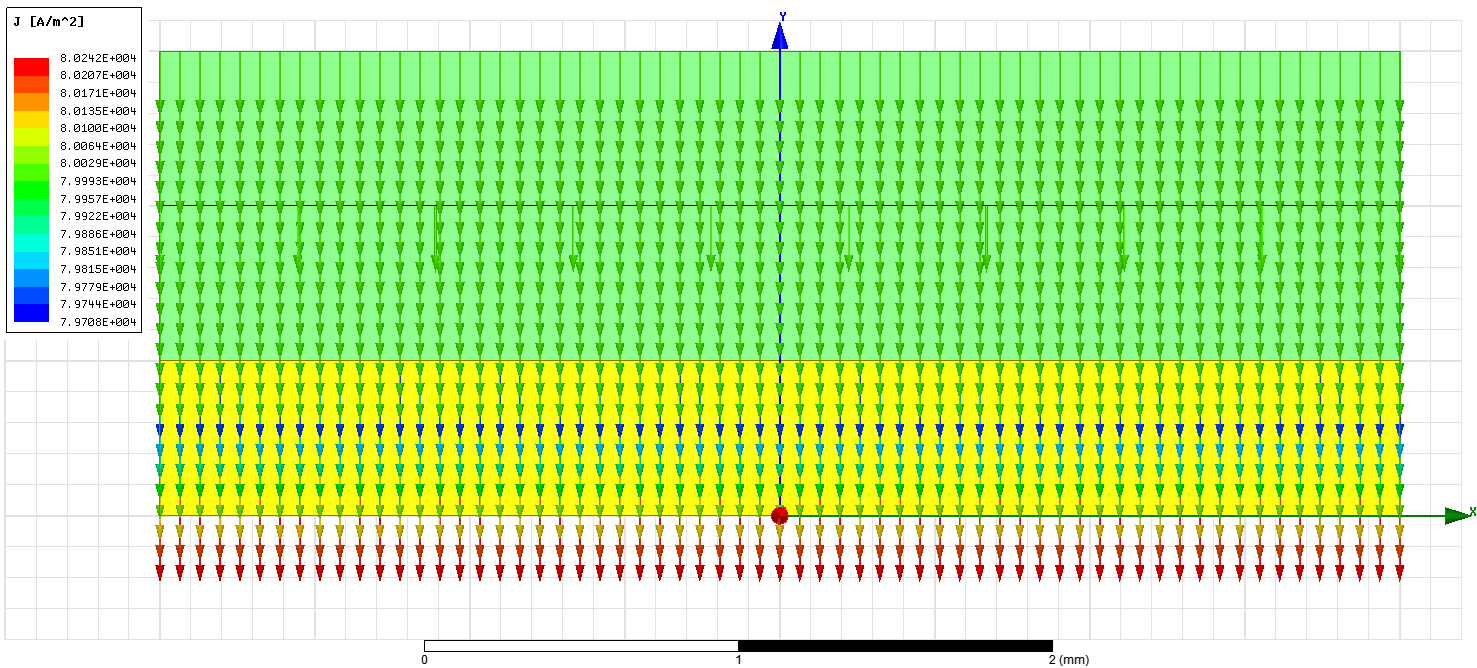
• Plot Current Density Vectors
– Select the menu item Edit Select Objects or press O from the keyboard
– Select the menu item Edit Select All
– Select the menu item Maxwell 2D Fields Fields J J_Vector
– In Create Field Plot window,
• Press Done
– Modify attributes of the plot by double clicking on the legend
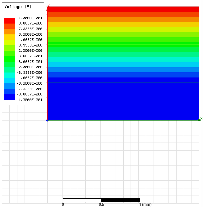
• Plot Voltage
– Select the menu item Edit Select All
– Select the menu item Maxwell 2D Fields Fields Voltage
– In Create Field Plot window,
• Press Done

Example 2: Parallel Plates with Non-uniform media in RZ Plane
• In this example, we illustrate the capability of the DC current solver to reconstruct the current paths flowing in different conductors
•在此示例中,我们说明了直流电流求解器重构在不同导体中流动的电流路径的能力
【Step01:建立工程文档,并设置基本参数】
• Create Design
– Select the menu item Project Insert Maxwell 2D Design, or click on the
icon
– Change the name of the design to Plates2
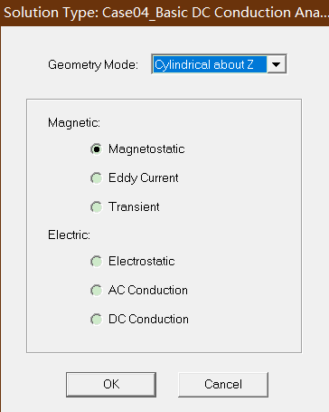
• Set Solution Type
– Select the menu item Maxwell 2D Solution Type
– Solution Type Window:
1. Geometry Mode: Cylindrical about Z
2. Choose DC Conduction
3. Click the OK button
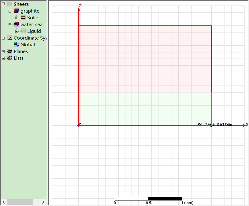
【Step02:Create Geometry 创建几何体】
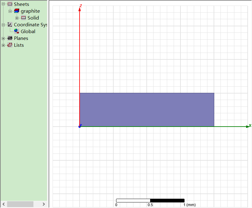
• Create Solid
– Select the menu item Draw Rectangle
1. Using the coordinate entry fields, enter the box position
– X: 0, Y: 0, Z: 0, Press the Enter key
2. Using the coordinate entry fields, enter the opposite corner
– dX: 2, dY: 0, dZ: 0.5, Press the Enter key
– Change the name of the sheet to Solid and material to graphite
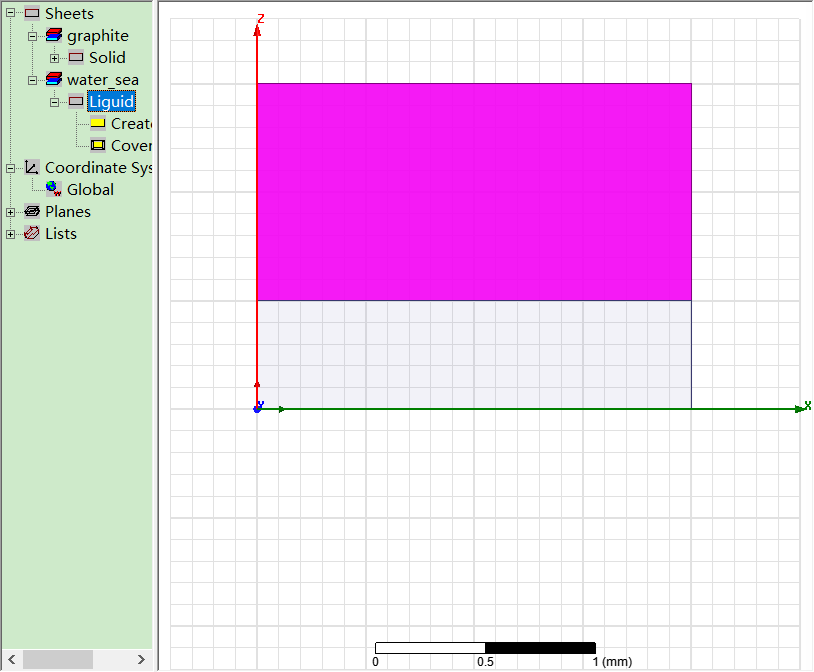
• Create Liquid
– Select the menu item Draw Rectangle
1. Using the coordinate entry fields, enter the box position
– X: 0, Y: 0, Z: 0.5, Press the Enter key
2. Using the coordinate entry fields, enter the opposite corner
– dX: 2, dY: 0, dZ: 1, Press the Enter key
– Change the name of the sheet to Liquid and material to water_sea
【Step03:Assign Excitations 分配激励】
• Assign Excitation for Top
– Select the menu item Edit Select Edges or press E from the keyboard
– Select the top edge of the sheet Liquid
– Select the menu item Maxwell 2D Excitations Assign Voltage
– In Voltage Excitation window,
1. Set Value to 10 V
2. Press OK

• Assign Excitation for Bottom
– Select the bottom edge of the sheet Solid
– Select the menu item Maxwell 2D Excitations Assign Voltage
– In Voltage Excitation window,
1. Set Value to -10 V
2. Press OK
【Step04:Analyze 分析】
• Create an analysis setup:
– Select the menu item Maxwell 2D Analysis Setup Add Solution Setup
– Solution Setup Window:
1. Click the OK to accept default settings
• Start the solution process:
– Select the menu item Maxwell 2D Analyze All
【Step05:Compute the DC Resistance 计算直流电阻】
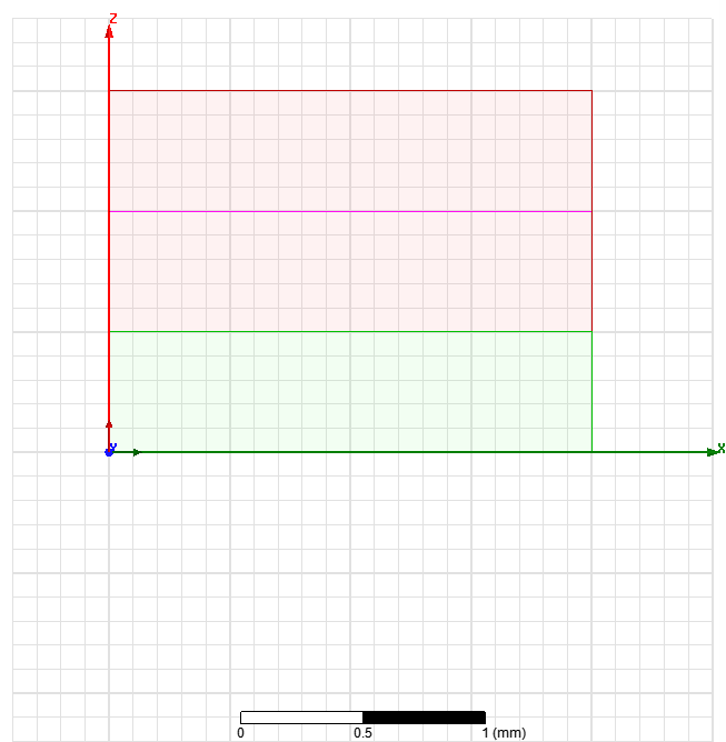
• Create Line
– Select the menu item Draw Line
• A massage will pop up asking if the geometry needs to be created as a nonmodel object, press Yes
1. Using the coordinate entry fields, enter the first point
– X: 0, Y: 0, Z: 1, Press the Enter key
2. Using the coordinate entry fields, enter the second point
– X: 2, Y: 0, Z: 1, Press the Enter key
3. Press Enter again to exit the drawing
– Change the name of the line to Sec_Line
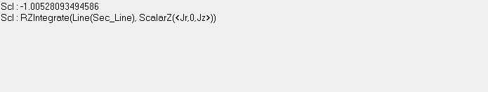
• Calculate Resistance
– Select the menu item Maxwell 2D Fields Calculator
– The total current going through the media is the RZ integral of the current J on
the line Sec_Line
– In Field Calculator window
1. Select Input > Quantity > J
2. Select Vector > Scal? > ScalarZ
3. Select Input > Geometry
– Select Line > Sec_Line > Press OK
4. Select Scalar > Integral >RZ
5. Press Eval
– The total current appears, close to -1.005A.
– The DC resistance is given by R = Voltage / Current. The difference of potential between the two plate is 20 V. We obtain R = 19.9 Ohm
• Analytical value of Resistance
– The analytical value of the resistance is given by the following formula
R = σ2h1 + σ1h2 / ( σ1σ2A)
where σ1, σ2 are the conductivity of the two medium, h1,h2 the thickness of the two medium R is radius of plates and A the surface of the plates.
– If we take below values,
• σ1 = 70000 Siemens/m,
• h1= 0.5e-3 m (ferrite);
• σ2 = 4 Siemens/m,
• h2 = 1e-3 m (sea water) ;
• R = 2e-3 m
• A = R2 =12.566 e-6 m2.
– The value of resistance comes out to be:
R = 19.9 Ohm
– The values are similar to what we obtained using Maxwell
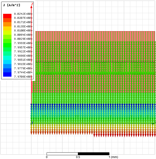
【Step06:Field Plots 绘制场图】
• Plot Current Density Vectors
– Select the menu item Edit Select Objects or press O from the keyboard
– Select the menu item Edit Select All
– Select the menu item Maxwell 2D Fields Fields J J_Vector
– In Create Field Plot window,
• Press Done
– Modify attributes of the plot by double clicking on the legend
• Plot Voltage
– Select the menu item Edit Select All
– Select the menu item Maxwell 2D Fields Fields Voltage
– In Create Field Plot window,
• Press Done

 浙公网安备 33010602011771号