
FIR仿真module_04
作者:桂。
时间:2018-02-06 12:10:14
链接:http://www.cnblogs.com/xingshansi/p/8421001.html
前言
本文主要记录基本的FIR实现,以及相关的知识点。
一、基本型实现
首先从最基本的FIR入手:
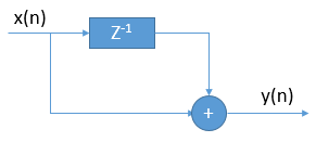
对应module:
`default_nettype	none
//
module	smplfir(i_clk, i_ce, i_val, o_val);
	parameter			IW=15;
	localparam			OW=IW+1;
	input	wire			i_clk, i_ce;
	input	wire	[(IW-1):0]	i_val;
	output	reg	[(OW-1):0]	o_val;

	reg	[(IW-1):0]	delayed;

	initial	delayed = 0;
	always @(posedge i_clk)
		if (i_ce)
			delayed <= i_val;

	always @(posedge i_clk)
		if (i_ce)
			o_val <= i_val + delayed;

endmodule
二、通用版FIR
前文里最多涉及阶数为5的FIR,这里给出适用任意阶、给定位宽的FIR。
A-参数转化
vivado仿真用到浮点->定点,需要将给定数据转为定点补码、或通过补码读取数据。
1)浮点转定点补码:
clc;clear all;close all;
%=============产生输入信号==============%
N=12; %数据位宽
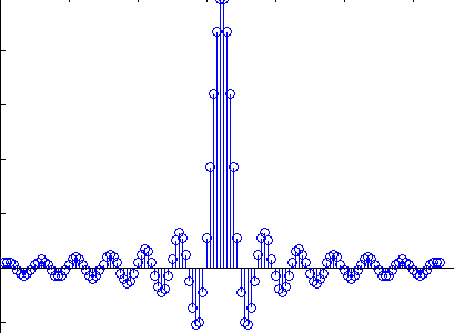
load fir128.mat;
y_n = fir128;
y_n=round(y_n*(2^(N-3)-1)); %N比特量化;如果有n个信号相加,则设置(N-n)
%=============设置系统参数==============%
L=length(y_n); %数据长度
%=================画图==================%
stem(1:L,y_n);
%=============写入外部文件==============%
fid=fopen('win.txt','w'); %把数据写入sin_data.txt文件中,如果没有就创建该文件
for k=1:length(y_n)
B_s=dec2bin(y_n(k)+((y_n(k))<0)*2^N,N);
for j=1:N
if B_s(j)=='1'
tb=1;
else
tb=0;
end
fprintf(fid,'%d',tb);
end
fprintf(fid,'\r\n');
end
fprintf(fid,';');
fclose(fid);
原型滤波器fir128为128阶的FIR滤波器。
生成的txt调用:$readmemb("*.txt",data);
2)给定补码,读取原数据:
clc;clear all;close all;
filename = 'win.txt';
fid = fopen(filename);
data_cell = textscan(fid,'%s','HeaderLines',0);
data = data_cell{1,1};
Nbit = 12;%number of bits
len = length(data)-1;%length of filter
wins = zeros(1,len);
for i = 1:len
str_win = data{i};
if (str_win(1) == '0')
wins(i) = bin2dec(str_win(2:end));
end
if (str_win(1) == '1')
wins(i) = -bin2dec(num2str(ones(1,Nbit-1)))+bin2dec(str_win(2:end));
end
end
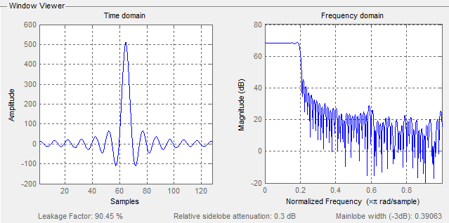
wvtool(wins)
得到滤波器特性如下图所示,当然也可以hex2dec转为16进制,思路一致。
B-仿真模型
testbench:
`timescale 1ns / 1ps
module tb;
    // Inputs
    reg Clk;
    reg rst;
    // Outputs
    parameter datawidth = 12;
    wire signed [2*datawidth-1:0] Yout;
    //Generate a clock with 10 ns clock period.
initial  Clk <= 0;

always #5 Clk = ~Clk;

//Initialize and apply the inputs.
//-------------------------------------//
parameter data_num = 32'd1024;
integer   i = 0;
reg [datawidth-1:0]  Xin[1:data_num];
reg  [datawidth-1:0]  data_out;

initial begin
 rst = 1;
#20
  rst = 0;
    $readmemb("D:/PRJ/vivado/simulation_ding/009_lpf6tap/matlab/sin_data.txt",Xin);
end


 always @(posedge Clk) begin
 if(rst)
 begin
    data_out <= 0;
 end
 else
 begin
    data_out <= Xin[i];
    i <= i + 8'd1;
    end
end

fastfir firinst(
.i_clk(Clk),
.i_reset(rst),
.i_ce(1'b1),
.i_sample(data_out),
.o_result(Yout)
);
endmodule
fast.v:
//
`default_nettype	none
//
module	fastfir(i_clk, i_reset, i_ce, i_sample, o_result);
	parameter		NTAPS=127, IW=12, TW=IW, OW=2*IW+7;
	input	wire			i_clk, i_reset;
	//
	input	wire			i_ce;
	input	wire	[(IW-1):0]	i_sample;
	output	wire signed	[(2*IW-1):0]	o_result;

	reg 	[(TW-1):0] tap		[0:NTAPS];
	wire	[(TW-1):0] tapout	[NTAPS:0];
	wire	[(IW-1):0] sample	[NTAPS:0];
	wire	[(OW-1):0] result	[NTAPS:0];
	wire		tap_wr;
	// The first sample in our sample chain is the sample we are given
	assign	sample[0]	= i_sample;
	// Initialize the partial summing accumulator with zero
	assign	result[0]	= 0;

     //observe filter
     reg [IW-1:0] fir_coef;
     integer i = 0;
     always @(posedge i_clk)
     begin
        if(i_reset) fir_coef <= 0;
        else
        begin
            fir_coef <= tap[i];
            i <= i+ 8'd1;
        end
     end
	genvar	k;
	generate
	begin
		initial $readmemb("D:/PRJ/vivado/simulation_ding/009_lpf6tap/matlab/win.txt", tap);
		assign	tap_wr = 1'b1;
	end
	for(k=0; k<NTAPS; k=k+1)
	begin: FILTER

		firtap #(.FIXED_TAPS(1'b1),
				.IW(IW), .OW(OW), .TW(TW),
				.INITIAL_VALUE(0))
				tapk(
				.i_clk(i_clk),
				.i_reset(i_reset),
				.i_tap_wr(tap_wr),
				.i_tap( tap[k]),
				.o_tap(tapout[k+1]),
				.i_ce(i_ce),
				.i_sample(sample[0]),
				.o_sample(sample[k+1]),
                .i_partial_acc(result[k]),
                .o_acc( result[k+1])
                );
	end endgenerate

	assign	o_result = result[NTAPS][2*IW-1:0];

endmodule
firtap.v:
//
`default_nettype	none
//
module	firtap(i_clk, i_reset, i_tap_wr, i_tap, o_tap,
		i_ce, i_sample, o_sample,
		i_partial_acc, o_acc);
	parameter		IW=12, TW=IW, OW=IW+TW+8;
	parameter [0:0]		FIXED_TAPS=1;
	parameter [(TW-1):0]	INITIAL_VALUE=0;
	//
	input	wire			i_clk, i_reset;
	//
	input	wire			i_tap_wr;
	input	wire	[(TW-1):0]	i_tap;
	output	wire signed [(TW-1):0]	o_tap;
	//
	input	wire			i_ce;
	input	wire signed [(IW-1):0]	i_sample;
	output	reg 	[(IW-1):0]	o_sample;
	//
	input	wire	[(OW-1):0]	i_partial_acc;
	output	reg 	[(OW-1):0]	o_acc;
	//

	reg		[(IW-1):0]	delayed_sample;
	reg	signed	[(TW+IW-1):0]	product;

	// Determine the tap we are using
	generate
	if (FIXED_TAPS != 0)
		// If our taps are fixed, the tap is given by the i_tap
		// external input.  This allows the parent module to be
		// able to use readmemh to set all of the taps in a filter
		assign	o_tap = i_tap;

	else begin
		// If the taps are adjustable, then use the i_tap_wr signal
		// to know when to adjust the tap.  In this case, taps are
		// strung together through the filter structure--our output
		// tap becomes the input tap of the next tap module, and
		// i_tap_wr causes all of them to shift forward by one.
		reg	[(TW-1):0]	tap;

		initial	tap = INITIAL_VALUE;
		always @(posedge i_clk)
			if (i_tap_wr)
				tap <= i_tap;
		assign o_tap = tap;

	end endgenerate

	// Forward the sample on down the line, to be the input sample for the
	// next component
	always @(posedge i_clk)
		if (i_reset)
		begin
			delayed_sample <= 0;
			o_sample <= 0;
		end else if (i_ce)
		begin
			// Note the two sample delay in this forwarding
			// structure.  This aligns the inputs up so that the
			// accumulator structure (below) works.
			delayed_sample <= i_sample;
			o_sample <= delayed_sample;
		end

	// Multiply the filter tap by the incoming sample
	always @(posedge i_clk)
		if (i_reset)
			product <= 0;
		else if (i_ce)
			product <= o_tap * i_sample;

	// Continue summing together the output components of the FIR filter
	always @(posedge i_clk)
		if (i_reset)
			o_acc <= 0;
		else if (i_ce)
			o_acc <= i_partial_acc
				+ { {(OW-(TW+IW)){product[(TW+IW-1)]}},
						product };


	// Make verilator happy
	// verilate lint_on  UNUSED
	wire	unused;
	assign	unused = i_tap_wr;
	// verilate lint_off UNUSED
endmodule
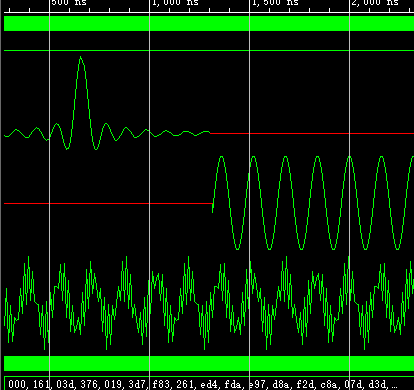
仿真结果:

 浙公网安备 33010602011771号