
Cordic算法简介
作者:桂。
时间:2017-08-14 19:22:26
链接:http://www.cnblogs.com/xingshansi/p/7359940.html
前言
CORDIC算法常用来求解信号的幅度与相位,它的优势在于借助:移位寄存器+加法器/减法器便可以实现求解,而无需乘法器。大大简化了运算。本文围绕CORDIC整理用到的知识,先做个引子,不定期更新。
一、CORDIC算法
CORDIC(Coordinate Rotation Digital Computer) 算法由Volder于1959年提出,该算法利用移位和加减运算,实现常用三角函数计算。
A-二分查找
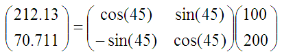
现在给定一坐标点(X = 100,Y = 200)可知theta = 63.435°。

这里只讨论第一象限,当四个象限同时讨论时,只需要根据x,y的符号位给定一个标志位,对theta进行补偿即可。CORDIC的核心思想:将(X,Y)旋转一定的角度,当纵坐标为0时,旋转的角度就是theta。顺时针旋转theta后的坐标为(x',y'):

如何旋转呢,可以借鉴二分查找法的思想。我们知道θ的范围是0到90度。那么就先旋转45度试试。这里为什么选择45°呢?个人的理解:
tan(x/y) = 90° - tan(y/x)
可见45°是一个分界线。
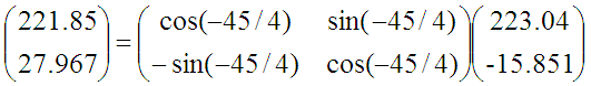
旋转之后纵坐标为70.71,还是大于0,说明旋转的度数不够,接着再旋转22.5度(45度二分)

这时总共旋转了45+22.5=67.5度。结果纵坐标变为了负数,说明θ<67.5度,这时就要往回转,还是二分查找法的思想,这次转-11.25度(回转为负角度)。
依次类推,直到迭代的结果满足要求为止。什么时候满足要求呢?这个需要根据项目要求的精度确定,例如误差<0.5°,即45°/2(n-1)<0.5°,二分次数n最小取8。可见只需要存取8个特定角度的正弦+8个特定角度的余弦,便可以实现角度的估计,这少量的数值可以提前写入存储器,运行时直接调用。
B-角度运算的初步改进
从旋转矩阵可以看出,每二分查找一次,就需要4次乘法运算。为了减小运算量,对旋转矩阵进一步处理:
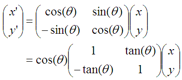
求解相位时,cos(theta)只影响x,y的比例关系,而比例并不影响theta的取值,因此可以忽略:
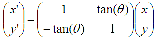
这样便将每次二分的4次乘法运算缩减为2次。
C-角度运算的进一步改进
注意到第一次循环时,tan(45)=1,所以第一次循环实际上是不需要乘法运算的。第二次运算tan(22.5)=0.4142135623731,是个很不整的小数,如果参与乘法的小数比较有规律/比较整,则乘法运算会简化一些,因此这里转化思路:不再严格的二分区间查找,而是非均匀分割角度区间,使得tan(theta)尽可能整→这样一来,乘法不再需要乘法器,而是移位便可以实现。
tan(45)= 1
tan(26.565051177078)= 1/2
tan(14.0362434679265)= 1/4
tan(7.1250163489018)= 1/8
tan(3.57633437499735)= 1/16
tan(1.78991060824607)= 1/32
tan(0.8951737102111)= 1/64
tan(0.4476141708606)= 1/128
tan(0.2238105003685)= 1/256
...
MATLAB仿真(迭代次数由项目指标给定的精度确定):
function theta = cordic(x,y)
%仅以第一象限为例
angle = atand(2.^([0:-1:-15]));
len = length(angle);
theta = 0;
for i = 0:len-1
    if (y>0)
        x_new = x+y*2^-i;%此处移位寄存器实现
        y_new = y-x*2^-i;%此处移位寄存器实现
        x = x_new;
        y = y_new;
        theta = theta+angle(i+1);
    else
        x_new = x-y*2^-i;%此处移位寄存器实现
        y_new = y+x*2^-i;%此处移位寄存器实现
        x = x_new;
        y = y_new;
        theta = theta-angle(i+1);
    end
end
至此便完成了CORDIC的整体思路。其他函数可仿照该思路类推。
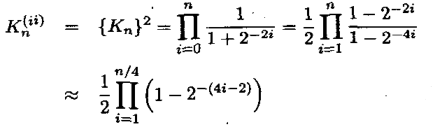
CORDIC求解幅值的思路:
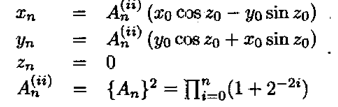
可近似处理:
具体参考:《Design of Jacobi EVD processor based on CORDIC for DOA estimation with MUSIC algorithm》
二、求解三角思路延伸
以arctan为例,迭代次数随着theta精度的增加而增加,迭代次数过多会导致时间延迟过大,因此可以考虑函数逼近的思路。常用的有泰勒逼近和切比雪夫逼近。
因为tan(45°) = 1,且tan(x/y) = 90°-tan(y/x),因此arctan(x)只需要讨论x属于[0,1]的情况,这一点刚好满足切比雪夫近似。
A-泰勒逼近
即高等数学里的泰勒展开:

对应的指令:
syms x
y = atan(x);
p50=taylor(y,'Order',3,'ExpansionPoint',0.5);
Order:指定阶数,expansionpoint:指定展开的位置。
求解:
double(subs(p50,x,i));%i为指定位置的数值
B-切比雪夫逼近
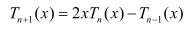
切比雪夫多项式可表示为:
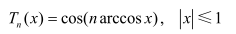
设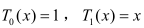 ,可以求得以下递推关系:
函数f(x)可以近似表达为傅里叶级数:
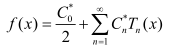
其中:
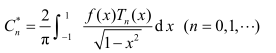
这就完成了切比雪夫近似的思想。
给出代码实现:
function f = Chebyshev(y,k,x0)
%用切比雪夫多项式逼近已知函数
%已知函数:y(类型:表达式)
%逼近已知函数所需项数:k
%逼近点的x坐标:x0
%求得的切比雪夫逼近多项式或在x0处的逼近值:f

syms t;
T(1:k+1) = t;
T(1) = 1;
T(2) = t;
c(1:k+1) = 0.0;

c(1)=quad(matlabFunction(y(t)*T(1)/sqrt(1-t^2)),-1,1)/pi;
c(2)=2*quad(matlabFunction(y(t)*T(2)/sqrt(1-t^2)),-1,1)/pi;
f = c(1)+c(2)*t;

for i=3:k+1
    T(i) = 2*t*T(i-1)-T(i-2);
    c(i) = 2*quad(matlabFunction(y(t)*T(i)/sqrt(1-t^2)),-1,1)/pi;
    f = f + c(i)*T(i);
    f = vpa(f,6);

    if(i==k+1)
        if(nargin == 3)
            f = subs(f,'t',x0);
        else
            f = vpa(expand(f),6);
        end
    end
end
函数中vpa用来控制精度,例如:
digits(3);%控制精度
vpa(1/3);
结果便是0.333,而不是0.33333333...
调用形式:
Chebyshev(y,3,i);%i为对应横坐标
这里对于taylor、chebv展开,都按3阶处理(其他阶数类似),得出逼近误差:
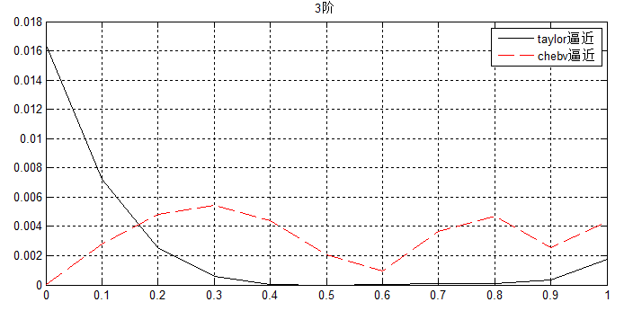
可以看出chebv的逼近更加稳健。
三、CORDIC仿真
分两个思路整理,首先是调用IP核,其次是不使用IP核。
A-调用IP核
直接看使用手册即可。
B-不使用IP核
//CORDIC implementation for sine and cosine for Final Project

//Claire Barnes

module CORDIC(clock, cosine, sine, x_start, y_start, angle);

  parameter width = 16;

  // Inputs
  input clock;
  input signed [width-1:0] x_start,y_start;
  input signed [31:0] angle;

  // Outputs
  output signed  [width-1:0] sine, cosine;

  // Generate table of atan values
  wire signed [31:0] atan_table [0:30];

  assign atan_table[00] = 'b00100000000000000000000000000000; // 45.000 degrees -> atan(2^0)
  assign atan_table[01] = 'b00010010111001000000010100011101; // 26.565 degrees -> atan(2^-1)
  assign atan_table[02] = 'b00001001111110110011100001011011; // 14.036 degrees -> atan(2^-2)
  assign atan_table[03] = 'b00000101000100010001000111010100; // atan(2^-3)
  assign atan_table[04] = 'b00000010100010110000110101000011;
  assign atan_table[05] = 'b00000001010001011101011111100001;
  assign atan_table[06] = 'b00000000101000101111011000011110;
  assign atan_table[07] = 'b00000000010100010111110001010101;
  assign atan_table[08] = 'b00000000001010001011111001010011;
  assign atan_table[09] = 'b00000000000101000101111100101110;
  assign atan_table[10] = 'b00000000000010100010111110011000;
  assign atan_table[11] = 'b00000000000001010001011111001100;
  assign atan_table[12] = 'b00000000000000101000101111100110;
  assign atan_table[13] = 'b00000000000000010100010111110011;
  assign atan_table[14] = 'b00000000000000001010001011111001;
  assign atan_table[15] = 'b00000000000000000101000101111100;
  assign atan_table[16] = 'b00000000000000000010100010111110;
  assign atan_table[17] = 'b00000000000000000001010001011111;
  assign atan_table[18] = 'b00000000000000000000101000101111;
  assign atan_table[19] = 'b00000000000000000000010100010111;
  assign atan_table[20] = 'b00000000000000000000001010001011;
  assign atan_table[21] = 'b00000000000000000000000101000101;
  assign atan_table[22] = 'b00000000000000000000000010100010;
  assign atan_table[23] = 'b00000000000000000000000001010001;
  assign atan_table[24] = 'b00000000000000000000000000101000;
  assign atan_table[25] = 'b00000000000000000000000000010100;
  assign atan_table[26] = 'b00000000000000000000000000001010;
  assign atan_table[27] = 'b00000000000000000000000000000101;
  assign atan_table[28] = 'b00000000000000000000000000000010;
  assign atan_table[29] = 'b00000000000000000000000000000001;
  assign atan_table[30] = 'b00000000000000000000000000000000;

  reg signed [width:0] x [0:width-1];
  reg signed [width:0] y [0:width-1];
  reg signed    [31:0] z [0:width-1];


  // make sure rotation angle is in -pi/2 to pi/2 range
  wire [1:0] quadrant;
  assign quadrant = angle[31:30];

  always @(posedge clock)
  begin // make sure the rotation angle is in the -pi/2 to pi/2 range
    case(quadrant)
      2'b00,
      2'b11: // no changes needed for these quadrants
      begin
        x[0] <= x_start;
        y[0] <= y_start;
        z[0] <= angle;
      end

      2'b01:
      begin
        x[0] <= -y_start;
        y[0] <= x_start;
        z[0] <= {2'b00,angle[29:0]}; // subtract pi/2 for angle in this quadrant
      end

      2'b10:
      begin
        x[0] <= y_start;
        y[0] <= -x_start;
        z[0] <= {2'b11,angle[29:0]}; // add pi/2 to angles in this quadrant
      end
    endcase
  end


  // run through iterations
  genvar i;

  generate
  for (i=0; i < (width-1); i=i+1)
  begin: xyz
    wire z_sign;
    wire signed [width:0] x_shr, y_shr;

    assign x_shr = x[i] >>> i; // signed shift right
    assign y_shr = y[i] >>> i;

    //the sign of the current rotation angle
    assign z_sign = z[i][31];

    always @(posedge clock)
    begin
      // add/subtract shifted data
      x[i+1] <= z_sign ? x[i] + y_shr : x[i] - y_shr;
      y[i+1] <= z_sign ? y[i] - x_shr : y[i] + x_shr;
      z[i+1] <= z_sign ? z[i] + atan_table[i] : z[i] - atan_table[i];
    end
  end
  endgenerate

  // assign output
  assign cosine = x[width-1];
  assign sine = y[width-1];

endmodule
参考:
- http://blog.csdn.net/liyuanbhu/article/details/8458769

 浙公网安备 33010602011771号