Qt - Graphics View(图形视图)
Qt提供了图形视图框架(Graphics View Framework)、动画框架(The AnimationFramework)和状态机框架(The State Machine Framework)来实现更加高级的图形和动画应用。使用这些框架可以快速设计出动态GUI应用程序和各种动画,游戏程序。
1、图形视图框架简介
QT4.2开始引入了Graphics View框架用来取代QT3中的Canvas模块,并作出了改进,Graphics View框架实现了模型-视图结构的图形管理,能对大量图元进行管理,支持碰撞检测,坐标变换和图元组等多种方便的功能。
GraphicsView框架结构主要包含三个主要的类QGraphicsScene(场景)、QGraphicsView(视图)、QGraphicsItem(图元)。QGraphicsScene本身不可见,是一个存储图元的容器,必须通过与之相连的QGraphicsView视图来显示及与外界进行交互,主要提供图元的操作接口、传递事件和管理各个图元状态,提供无变换的绘制功能(如打印);QGraphicsView提供一个可视的窗口,用于显示场景中的图元,一个场景中可以有多个视图。QGraphicsItem是场景中各个图元的基础类,QT提供了常用图形图元的标准类,如矩形(QGraphicsRectItem)、椭(QGraphicsEllipseItem)、文本(QGraphicsTextItem)。
GraphicsView是一个基于图元的Model/View架构的框架,每一个组件都是一个独立的元素。QPainter采用面向过程的描述方式绘图;GraphicsView采用面向对象的描述方式绘图。GraphicsView绘图时首先创建一个场景,然后创建图元对象(如一个直线对象、一个多边形对象),再使用场景的add()函数,将图元对象添加到场景中,最后通过视图进行显示。对于复杂的图像来说,如果图像包含大量的直线、曲线、多边形等图元对象,管理图元对象比管理QPainter的绘制过程语句要容易,并且图元对象更符合面向对象的思想,图形的可复用性更好。
2、QGraphicsScene 场景
QGraphicsScene场景是QGraphicsItem对象的容器,主要功能如下:
-
提供一个快速的接口,用于管理大量图元。
-
向每个图元传递事件
-
管理图元的状态,如:选中、焦点处理
-
提供未进行坐标转换的渲染功能,主要用于打印
通过函数QGraphicsScene::addItem()可以加入一个图元到场景中。图元可以通过多个函数进行检索:QGraphicsScene::items()及重载函数可以返回和点、矩形、多边形或向量路径相交的所有图元。QGraphicsScene::itemAt()返回指定点的最顶层图元。所有图元查找函数按照递减栈顺序返回图元,第一个返回的图元位置最顶层,最后一个返回的图元位于最底层。
QGraphicsScene的事件传播体系将场景事件发送给图元,同时也管理图元之间的事件传播。如果场景收到了在某一点的鼠标单击事件,场景会把事件传给在这一点的最顶层图元。QGraphicsScene负责管理一些图元的状态,如图元选择和焦点。通过QGraphicsScene::setSeletionArea()函数选择多个图元,选择区域可以是任意的形状,使用 QPainterPath表示;要得到当前选择的图元列表可以使用 QGraphicsScene::selectedItems()函数;QGraphicsScene还管理图元的键盘输入焦点状态,可以通过QGraphicsScene::setFocusItem()函数或者QGraphicsItem::setFoucs()函数来设置图元的焦点;获得当前具有焦点的图元使用函数QGraphicsScene::foucsItem()。可以使用 QGraphicsScene::render()函数在绘图设备上绘制场景。
示例代码:
#include <QApplication>
#include <QGraphicsScene>
#include <QGraphicsView>
#include <QGraphicsRectItem>
#include <QDebug>

int main(int argc, char *argv[])
{
    QApplication a(argc, argv);

    //新建场景
    QGraphicsScene* secne = new QGraphicsScene;
    //创建图形项
    QGraphicsRectItem* rectItem = new QGraphicsRectItem(0,0,100,100);
    //将图形项添加到场景中
    secne->addItem(rectItem);
    //输出(50,50)点出的图形项
    qDebug()<<secne->itemAt(50,50,QTransform());

    return a.exec();
}这里先创建了一个场景,然后创建了一个矩形图形项,并且将该图形项添加到了场景中。然后使用itemAt()函数返回指定坐标处最顶层的图形项,这里返回的就是刚才添加的矩形图形项。现在可以运行程序,不过因为还没有设置视图,所以不会出现任何图形界面。这时可以在应用程序输出栏中看到输出项目的信息,要关闭运行的程序,则可以按下应用程序输出栏上的红色按钮,然后强行关闭应用程序。
QGraphicsScene的事件传播构架可以将场景事件传递给图形项,也可以管理图形项之间事件的传播。例如,如果场景在一个特定的点接收到了一个鼠标按下事件,那么场景就会将这个事件传递给该点的图形项。
QGraphicsScene也用来管理图形项的状态,如图形项的选择和焦点等。可以通过向QGraphicsScene: :setSelectionArea()函数传递一个任意的形状来选择场景中指定的图形项。如果要获取当前选取的所有图形项的列表,则可以使用QGraphicsScene: :selectedItems()函数。另外可以调用QGraphicsScene: : setFocusItem()或者QGraphicsScene: : setFocus()函数来为一个图形项设置焦点,调用QGraphicsScene : : focus-Item()函数获取当前获得焦点的图形项。
QGraphicsScene也可以使用QGraphicsScene: : render()函数将场景中的一部分渲染到一个绘图设备上。这里讲到的这些函数会在后面的内容中看到它们的应用。
3、QGraphicsView 视图
QGraphicsView是视图窗口部件,使场景内容可视化,可以连接多个视图到一个场景,也可以为相同数据源的数据集提供不同的视图。QGraphicsView是可滚动的窗口部件,可以提供滚动条来浏览大的场景。如果需要使用OpenGL,可以使用QGraphicsView::setViewport()将视图设置为QGLWidget组件。
视图接收键盘和鼠标的输入事件,并把事件翻译为场景事件(将坐标转换为场景的坐标),再发送到场景。使用变换矩阵函数QGraphicsView::martix()可以变换场景的坐标系统,通过变换场景的坐标系统可以实现场景的缩放和旋转。为了方便,QGraphicsView提供了视图和场景的坐标转换函数:QGraphicsView::mapToScene()和QGraphicsView::mapFromScene()。
示例代码:
#include <QApplication>
#include <QGraphicsScene>
#include <QGraphicsView>
#include <QGraphicsRectItem>
#include <QDebug>

int main(int argc, char *argv[])
{
    QApplication a(argc, argv);

    //新建场景
    QGraphicsScene* secne = new QGraphicsScene;
    //创建图形项
    QGraphicsRectItem* rectItem = new QGraphicsRectItem(0,0,100,100);
    //将图形项添加到场景中
    secne->addItem(rectItem);

    //创建视图
    QGraphicsView view(secne);
    //view.setScene(secne);    //也可以这样设置场景
    //设置场景的前景色
    view.setForegroundBrush(QColor(255,255,0,100));
    //设置场景的背景色
    view.setBackgroundBrush(QPixmap("://images/background.png"));
    //设置场景与视图对齐
    view.setAlignment(Qt::AlignTop | Qt::AlignLeft);
    view.resize(640,480);
    view.show();

    return a.exec();
}
运行效果:
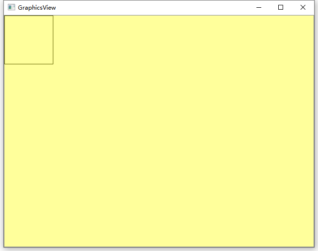
这里新建了视图部件,并指定了要可视化的场景。然后为该视图设置了场景前景色和背景图片。一个场景分为3层:图形项层(ItemLayer)、前景层(ForegroundLayer)和背景层(BackgroundLayer)。场景的绘制总是从背景层开始,然后是图形项层,最后是前景层。前景层和背景层都可以使用QBrush进行填充,比如使用渐变和贴图等。
代码中使用了QGraphicsView类中的函数设置了场景中的背景和前景,其实也可以使用QGraphicsScene 中的同名函数来实现,不过它们的效果并不完全一样。如果使用QGraphicsScene对象设置了场景背景或者前景,那么对所有关联了该场景的视图都有效,而QGraphicsView对象设置的场景的背景或者前景只对它本身对应的视图有效。
4、QGraphicsItem 图元
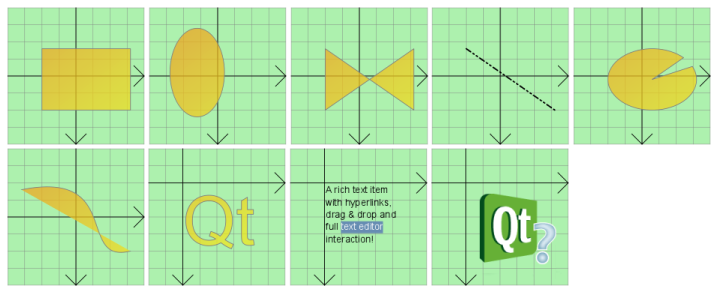
QGraphicsItem是图元的基类。QGraphics View框架提供了多种标准的图元,例如:矩形(QGraphicsRectlem)、椭圆(QGraphicsEllipseItem)和文本项(QGraphicsTextItcm)等等。
标准图元:
-
QGraphicsEllipseItem 提供了一个椭圆图元
-
QGraphicsLineItem 提供了一个线段图元
-
QGraphicsPathItem 提供任意路径图元
-
QGraphicsPixmapItem 提供了一个像素图图元
-
QGraphicsPolygonItem 提供了一个多边形图元
-
QGraphicsRectItem 提供了一个矩形图元
-
QGraphicsSimpleTextItem 提供了一个简单的文本标签图元
-
QGraphicsTextItem 提供了一个高级的文本浏览图元
用户可以继承QGraphicsItem实现自定义的图元。QGraphicsItem图元主要特性如下:
-
支持鼠标按下、移动、释放、双击、悬停、滚动和右键菜单事件。
-
支持键盘输入焦点和按键事件
-
支持拖拽事件
-
支持分组,使用父子关系和QGraphicsItemGroup
-
支持碰撞检测
图元存在于本地坐标系统上,场景提供了在图元和场景间、图元与图元间进行坐标变换的函数。QGraphicsItem::transform()函数可以使用矩阵转换坐标系统。这对于翻转和缩放图元是有用的。
图元可以包含其他图元,父图元的变换会被其所有的子图元继承。无论一个图元本身有多少变换,图元的所有函数(QGraphicsItem::contains(), QGraphicsItem::boundingRect(), QGraphicsItem::collidesWith())仍旧执行在本地坐标系上。
QGraphicsItem通过虚函数shape()和collideWith())来支持碰撞检测。从shape()返回图元的形状(以本地坐标QPainterPath表示),QGraphicsItem会处理所有的碰撞检测。如果要提供自己的碰撞检测,需要重新实现QGraphicsItem::collideWith()。
碰撞检测的方法:
a、重写shape()函数来返回图元的精准轮廓,依靠默认的collidesWithItem()来做外形交集。如果item轮廓和复杂时候,消耗是很大的。
b、重写collidesWithItem(),提供一个自己的图元和轮廓碰撞的算法
Contains()函数可以调用,用来决定一个图元是否包含一个点。Contains函数可以重写,contains()函数默认的方法是通过调用shape()来完成的。
图元中也可以包含其他的图元,也可以被别的图元包含,所有的图元可以有一个父类图元和多个子类图元,除非一个图元没有父类,否则图元的位置是在父类坐标中,子类图元将会继承父类图元的位置和转换。
通过调用setVisible(),可以设置图元是否可见,隐藏一个图元同时也隐藏了其子类,通过调用 setEnabled()来是指图元是否可用。如果禁用了图元,那么其所有的子类都不可用。图元默认都是可见和可用的。
示例代码1:绘制矩形
#include <QApplication>
#include <QGraphicsScene>
#include <QGraphicsView>
#include <QGraphicsRectItem>
#include <QDebug>

int main(int argc, char *argv[])
{
    QApplication a(argc, argv);

    //新建场景
    QGraphicsScene* secne = new QGraphicsScene;
    //创建图元
    QGraphicsRectItem* RectItem = new QGraphicsRectItem(10,10,50,50);
    //将图元添加到场景中
    secne->addItem(RectItem);
    //设置图元可移动的
    RectItem->setFlags(QGraphicsItem::ItemIsMovable | QGraphicsItem::ItemIsSelectable | QGraphicsItem::ItemIsFocusable);


    //创建视图
    QGraphicsView view(secne);//设置场景
    //view.setScene(secne);   //也可以这样设置场景
    //设置场景的前景色
    //view.setForegroundBrush(QColor(0,0,0,100));
    //设置场景的背景色
    view.setBackgroundBrush(QColor(255,255,255));
    //view.setBackgroundBrush(QPixmap("://images/background.png"));

    //设置场景与视图对齐
    view.setAlignment(Qt::AlignTop | Qt::AlignLeft);
    //设置拖动模式
    //view.setDragMode(QGraphicsView::RubberBandDrag);

    view.resize(640,480);
    view.show();

    return a.exec();
}
以上代码创建了一个可以拖动的矩形
运行效果:

示例代码2:绘制图片
    //QGraphicsView框架显示图片
    QGraphicsScene *scene = new QGraphicsScene(this);//创建创建
    QGraphicsPixmapItem *item = new QGraphicsPixmapItem();//创建qt标准图元
    item->setPixmap(QPixmap::fromImage(QImage("./7days_prom_de.jpg")));//设置图片
    scene->addItem(item);//往场景里添加图元
    QGraphicsView *view = new QGraphicsView(scene);
    view->setScene(scene);//QGraphicsView设置场景
运行效果:

4.1 自定义图形(三角形)
新建类文件,在头文件中加入如下代码:创建一个绘制三角形的Item
graphicstriangleitem.h
#ifndef GRAPHICSTRIANGLEITEM_H
#define GRAPHICSTRIANGLEITEM_H

#include<QGraphicsItem>

class GraphicsTriangleItem:public QGraphicsItem
{
public:
    GraphicsTriangleItem(int w,int h);

    QRectF boundingRect()const override;
    void paint(QPainter *painter, const QStyleOptionGraphicsItem *option, QWidget *widget)override;
private:
    int m_w;
    int m_h;
};

#endif // GRAPHICSTRIANGLEITEM_H
再到.cpp文件添加实现
graphicstriangleitem.cpp
#include "graphicstriangleitem.h"
#include <QPainter>
GraphicsTriangleItem::GraphicsTriangleItem(int w,int h):m_w(w),m_h(h)
{
}
QRectF GraphicsTriangleItem::boundingRect() const
{
return QRectF(0,0,m_w,m_h);
}
// 修正第三个点的坐标为(m_w, m_h)
void GraphicsTriangleItem::paint(QPainter *painter, const QStyleOptionGraphicsItem *, QWidget *)
{
QPoint triangle[3] = {
QPoint(m_w/2, 0), // 顶点
QPoint(0, m_h), // 左下角
QPoint(m_w, m_h) // 右下角(原错误点)
};
painter->setPen(Qt::black);
painter->setBrush(Qt::red);
painter->drawPolygon(triangle, 3);
// painter->drawLine(0,0,50,50); // 测试线可删除
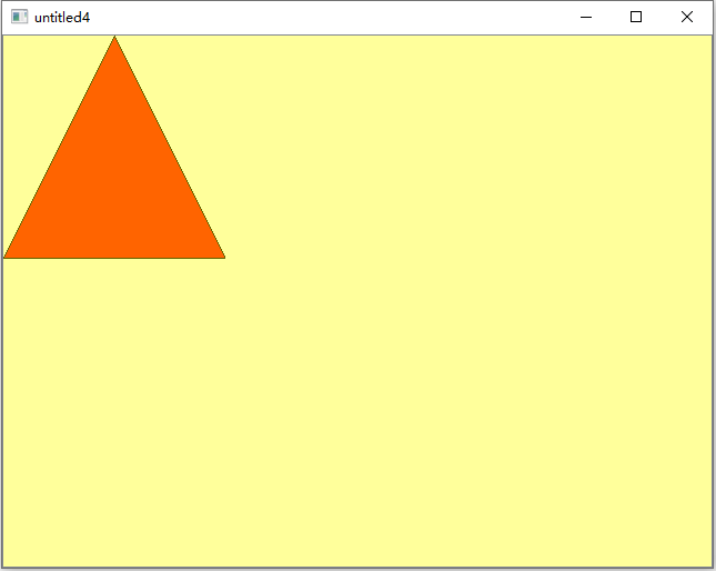
}要实现自定义的图形项,那么首先要创建一个QGraphicsItem的子类,然后重新实现它的两个纯虚公共函数: boundingRect()和 paint(),前者用来返回要绘制图形项的矩形区域,后者用来执行实际的绘图操作。其中, boundingRect()函数将图形项的外部边界定义为一个矩形,所有的绘图操作都必须限制在图形项的边界矩形之中。而且,QGraphicsView要使用这个矩形来剔除那些不可见的图形项,还要使用它来确定绘制交叉项目时哪些区域需要进行重新构建。另外,QGraphicsItem的碰撞检测机制也需要使用到这个边界矩形。如果图形绘制了一个轮廓,那么在边界矩形中包含一半画笔的宽度是很重要的,尽管对于抗锯齿绘图并不需要这些补偿。
boundingRect有两个参数,第一个是QPointF,第二个是QSizeF。其中第一个点坐标,设置的是,在item的边框矩阵内做一个坐标系,这个坐标系对应于边框矩阵左上角的点的坐标是什么。如果传(0, 0),则边界矩形左上角坐标就是(0, 0);如果传(- width / 2, -height / 2),边界矩形左上角坐标就是(- width / 2, -height / 2),从而(0, 0)点就被设置在了边界矩形的中心点。
使用自定义图形项:
#include <QApplication>
#include <QGraphicsScene>
#include <QGraphicsView>
#include <QGraphicsRectItem>
#include <QDebug>
#include "graphicstriangleitem.h"

int main(int argc, char *argv[])
{
    QApplication a(argc, argv);

    //新建场景
    QGraphicsScene* secne = new QGraphicsScene;
    //创建图形项
    //QGraphicsRectItem* rectItem = new QGraphicsRectItem(0,0,100,100);
    GraphicsTriangleItem* TriangleItem = new GraphicsTriangleItem(200,200);
    //将图形项添加到场景中
    //secne->addItem(rectItem);
    secne->addItem(TriangleItem);

    //创建视图
    QGraphicsView view(secne);//设置场景
    //view.setScene(secne);   //也可以这样设置场景
    //设置场景的前景色
    view.setForegroundBrush(QColor(255,255,0,100));
    //设置场景的背景色
    view.setBackgroundBrush(QPixmap("://images/background.png"));
    //设置场景与视图对齐
    view.setAlignment(Qt::AlignTop | Qt::AlignLeft);

    view.setDragMode(QGraphicsView::RubberBandDrag);

    view.resize(640,480);
    view.show();

    return a.exec();
}
运行效果:
4.2 自定义图形(矩形)
mygraphicrectitem.h
#ifndef MYGRAPHICRECTITEM_H
#define MYGRAPHICRECTITEM_H
#include <QObject>
#include <QWidget>
#include <QMouseEvent>
#include <QGraphicsScene>
#include <QGraphicsRectItem>
#include <QGraphicsSceneMouseEvent>
#include <QRect>
#include <QPainter>
#include <QPolygon>
#include <QList>

enum STATE_FLAG{
    DEFAULT_FLAG=0,
    MOV_LEFT_LINE,//标记当前为用户按下矩形的左边界区域
    MOV_TOP_LINE,//标记当前为用户按下矩形的上边界区域
    MOV_RIGHT_LINE,//标记当前为用户按下矩形的右边界区域
    MOV_BOTTOM_LINE,//标记当前为用户按下矩形的下边界区域
    MOV_RIGHTBOTTOM_RECT,//标记当前为用户按下矩形的右下角
    MOV_RECT,//标记当前为鼠标拖动图片移动状态
    ROTATE//标记当前为旋转状态
};
class myGraphicRectItem:public QObject,public QGraphicsItem
{
    Q_OBJECT
public:
    myGraphicRectItem(QGraphicsItem *parent = nullptr);
    //myGraphicRectItem(QRectF m_OriginRect = QRectF(0,0,100,100));
    QRectF  boundingRect() const;
    ~myGraphicRectItem();
    void setRectSize(QRectF mrect,bool bResetRotateCenter = true);
    void paint(QPainter *painter, const QStyleOptionGraphicsItem *option, QWidget *widget);
    void mousePressEvent(QGraphicsSceneMouseEvent *event);
    void mouseMoveEvent(QGraphicsSceneMouseEvent *event);
    void mouseReleaseEvent(QGraphicsSceneMouseEvent *event);
    void SetRotate(qreal RotateAngle,QPointF ptCenter=QPointF(-999,-999));
    QPointF getRotatePoint(QPointF ptCenter, QPointF ptIn, qreal angle);//获取旋转后的点
    QList<QPointF> getRotatePoints(QPointF ptCenter,QList<QPointF> ptIns,qreal angle);//获取多个旋转后的点
    QPolygonF getRotatePolygonFromRect(QPointF ptCenter,QRectF rectIn,qreal angle);//将矩形旋转之后返回多边形
    QRectF getCrtPosRectToSceen();
    QRectF m_SmallRotateRect;//矩形顶部用来表示旋转的标记的矩形
    QPolygonF m_SmallRotatePolygon;//矩形顶部用来表示旋转的标记的矩形旋转后形成的多边形
    QPointF getSmallRotateRectCenter(QPointF ptA,QPointF ptB);//获取旋转时候矩形正上方的旋转标记矩形
    QRectF  getSmallRotateRect(QPointF ptA,QPointF ptB);
    bool    m_bRotate;
    qreal   m_RotateAngle;
    QPointF m_RotateCenter;

private:
    QRectF  m_oldRect;
    QPolygonF m_oldRectPolygon;
    QRectF  m_RotateAreaRect;
    bool    m_bResize;
    QPolygonF m_insicedPolygon;
    QRectF  m_insicedRectf;
    QPolygonF m_leftPolygon;
    QRectF  m_leftRectf;
    QPolygonF m_topPolygon;
    QRectF  m_topRectf;
    QPolygonF m_rightPolygon;
    QRectF  m_rightRectf;
    QPolygonF m_bottomPolygon;
    QRectF  m_bottomRectf;
//    QPolygonF m_rbPolygon;
//    QRectF  m_rbRectf;
    QPointF m_startPos;
    STATE_FLAG m_StateFlag;
    QPointF *pPointFofSmallRotateRect;
protected:

};
#endif // MYGRAPHICRECTITEM_H
mygraphicrectitem.cpp
查看代码
 #include "mygraphicrectitem.h"
#include <QtMath>
#include <QDebug>

myGraphicRectItem::myGraphicRectItem(QGraphicsItem *parent):
    m_bResize(false),
    m_oldRect(0,0,100,100),
    m_bRotate(false),
    m_RotateAngle(0),
    m_StateFlag(DEFAULT_FLAG)
{
    //setParent(parent);
    setRectSize(m_oldRect);
    setToolTip("Click and drag me!");  //提示
    setCursor(Qt::ArrowCursor);   //改变光标形状,手的形状
    setFlag(QGraphicsItem::ItemIsMovable);
    //    setAcceptDrops(true);
    pPointFofSmallRotateRect = new QPointF[4];
    SetRotate(0);
    setFlag(QGraphicsItem::ItemIsSelectable);//
}

QRectF myGraphicRectItem::boundingRect() const
{
    //return m_oldRectPolygon.boundingRect();
    QRectF boundingRectF = m_oldRectPolygon.boundingRect();
    return QRectF(boundingRectF.x()-40,boundingRectF.y()-40,boundingRectF.width()+80,boundingRectF.height()+80);
}

myGraphicRectItem::~myGraphicRectItem()
{
    delete []pPointFofSmallRotateRect;
    pPointFofSmallRotateRect = nullptr;
}

void myGraphicRectItem::setRectSize(QRectF mrect, bool bResetRotateCenter)
{
    m_oldRect = mrect;
    if(bResetRotateCenter)
    {
        m_RotateCenter.setX(m_oldRect.x()+m_oldRect.width()/2);
        m_RotateCenter.setY(m_oldRect.y()+m_oldRect.height()/2);
    }
    m_oldRectPolygon = getRotatePolygonFromRect(m_RotateCenter,m_oldRect,m_RotateAngle);

    m_insicedRectf = QRectF(m_oldRect.x()+8,m_oldRect.y()+8,m_oldRect.width()-16,m_oldRect.height()-16);
    m_insicedPolygon =getRotatePolygonFromRect(m_RotateCenter,m_insicedRectf,m_RotateAngle);

    m_leftRectf = QRectF(m_oldRect.x(),m_oldRect.y(),8,m_oldRect.height()-8);
    m_leftPolygon = getRotatePolygonFromRect(m_RotateCenter,m_leftRectf,m_RotateAngle);

    m_topRectf = QRectF(m_oldRect.x()+8,m_oldRect.y(),m_oldRect.width()-8,8);
    m_topPolygon = getRotatePolygonFromRect(m_RotateCenter,m_topRectf,m_RotateAngle);

    m_rightRectf = QRectF(m_oldRect.right()-8,m_oldRect.y()+8,8,m_oldRect.height()-16);
    m_rightPolygon = getRotatePolygonFromRect(m_RotateCenter,m_rightRectf,m_RotateAngle);

    m_bottomRectf = QRectF(m_oldRect.x(),m_oldRect.bottom()-8,m_oldRect.width()-8,8);
    m_bottomPolygon = getRotatePolygonFromRect(m_RotateCenter,m_bottomRectf,m_RotateAngle);

//    m_rbRectf = QRectF(m_oldRect.right()-8,m_oldRect.bottom()-8,8,8);
//    m_rbPolygon = getRotatePolygonFromRect(m_RotateCenter,m_rbRectf,m_RotateAngle);

    m_SmallRotateRect = getSmallRotateRect(mrect.topLeft(),mrect.topRight());//矩形正上方的旋转标记矩形
    m_SmallRotatePolygon = getRotatePolygonFromRect(m_RotateCenter,m_SmallRotateRect,m_RotateAngle);
}

void myGraphicRectItem::paint(QPainter *painter, const QStyleOptionGraphicsItem *option, QWidget *widget)
{
    QPen mPen = QPen(Qt::yellow);
    painter->setPen(mPen);
    //绘制旋转后的矩形
    painter->drawPolygon(m_oldRectPolygon);
    //绘制旋转圆形
    mPen.setWidth(2);
    mPen.setColor(Qt::green);
    painter->setPen(mPen);
    QPointF pf = getSmallRotateRectCenter(m_oldRectPolygon[0],m_oldRectPolygon[1]);
    QRectF rect = QRectF(pf.x()-10,pf.y()-10,20,20);
    painter->drawEllipse(rect);//绘制圆形
    painter->drawPoint(pf);//绘制点
}

void myGraphicRectItem::mousePressEvent(QGraphicsSceneMouseEvent *event)
{
    if(event->button()== Qt::LeftButton)
    {
        m_startPos = event->pos();//鼠标左击时,获取当前鼠标在图片中的坐标,
        if(m_SmallRotatePolygon.containsPoint(m_startPos,Qt::WindingFill))//旋转矩形
        {
            setCursor(Qt::PointingHandCursor);
            m_StateFlag = ROTATE;
        }
        else if(m_insicedPolygon.containsPoint(m_startPos,Qt::WindingFill))//在矩形内框区域时按下鼠标,则可拖动图片
        {
            setCursor(Qt::ClosedHandCursor);   //改变光标形状,手的形状
            m_StateFlag = MOV_RECT;//标记当前为鼠标拖动图片移动状态
        }
        else if(m_leftPolygon.containsPoint(m_startPos,Qt::WindingFill))
        {
            setCursor(Qt::SizeHorCursor);
            m_StateFlag = MOV_LEFT_LINE;//标记当前为用户按下矩形的左边界区域
        }
        else if(m_rightPolygon.containsPoint(m_startPos,Qt::WindingFill))
        {
            setCursor(Qt::SizeHorCursor);
            m_StateFlag = MOV_RIGHT_LINE;//标记当前为用户按下矩形的右边界区域
        }
        else if(m_topPolygon.containsPoint(m_startPos,Qt::WindingFill))
        {
            setCursor(Qt::SizeVerCursor);
            m_StateFlag = MOV_TOP_LINE;//标记当前为用户按下矩形的上边界区域
        }
        else if(m_bottomPolygon.containsPoint(m_startPos,Qt::WindingFill))
        {
            setCursor(Qt::SizeVerCursor);
            m_StateFlag = MOV_BOTTOM_LINE;//标记当前为用户按下矩形的下边界区域
        }
//        else if(m_rbPolygon.containsPoint(m_startPos,Qt::WindingFill))
//        {
//            setCursor(Qt::SizeFDiagCursor);
//            m_StateFlag = MOV_RIGHTBOTTOM_RECT;//标记当前为用户按下矩形的右下角
//        }
        else
        {
            m_StateFlag = DEFAULT_FLAG;
        }
    }
    else
    {
        QGraphicsItem::mousePressEvent(event);
    }
}

void myGraphicRectItem::mouseMoveEvent(QGraphicsSceneMouseEvent *event)
{
    if(m_StateFlag == ROTATE)
    {
       int nRotateAngle = atan2((event->pos().x()-m_RotateCenter.x()),(event->pos().y()-m_RotateCenter.y()))*180/M_PI;
       SetRotate(180-nRotateAngle);
       setRectSize(m_oldRect);
       //qDebug()<<nRotateAngle;
    }
    else if(m_StateFlag == MOV_RECT)
    {
        QPointF point = (event->pos() - m_startPos);
        moveBy(point.x(), point.y());
        setRectSize(m_oldRect);
        scene()->update();
    }
    else if(m_StateFlag == MOV_LEFT_LINE)
    {
        QPointF pf = QPointF((m_oldRectPolygon.at(1).x()+m_oldRectPolygon.at(2).x())/2,((m_oldRectPolygon.at(1).y()+m_oldRectPolygon.at(2).y())/2));
        //计算到右侧边中点的距离
        qreal dis = sqrt((event->pos().x()-pf.x())*(event->pos().x()-pf.x()) +(event->pos().y()-pf.y())*(event->pos().y()-pf.y()));
        qreal dis2LT = sqrt((event->pos().x()-m_oldRectPolygon.at(0).x())*(event->pos().x()-m_oldRectPolygon.at(0).x()) +(event->pos().y()-m_oldRectPolygon.at(0).y())*(event->pos().y()-m_oldRectPolygon.at(0).y()));
        qreal dis2RT = sqrt((event->pos().x()-m_oldRectPolygon.at(1).x())*(event->pos().x()-m_oldRectPolygon.at(1).x()) +(event->pos().y()-m_oldRectPolygon.at(1).y())*(event->pos().y()-m_oldRectPolygon.at(1).y()));
        if(dis<16||dis2LT>dis2RT)
        {
            return;
        }
        else
        {
            QRectF newRect(m_oldRect);
            newRect.setLeft(m_oldRect.right()-dis);
            newRect.setRight(m_oldRect.right());
            setRectSize(newRect,false);
            m_RotateCenter=QPointF((m_oldRectPolygon.at(0).x()+m_oldRectPolygon.at(2).x())/2,(m_oldRectPolygon.at(0).y()+m_oldRectPolygon.at(2).y())/2);
            m_oldRect.moveCenter(m_RotateCenter);
            setRectSize(m_oldRect);
            scene()->update();//必须要用scene()->update(),不能用update();否则会出现重影
        }
    }
    else if(m_StateFlag == MOV_TOP_LINE)
    {
        //底边中点
        QPointF pf = QPointF((m_oldRectPolygon.at(2).x()+m_oldRectPolygon.at(3).x())/2,((m_oldRectPolygon.at(2).y()+m_oldRectPolygon.at(3).y())/2));
        //计算到底边中点的距离
        qreal dis = sqrt((event->pos().x()-pf.x())*(event->pos().x()-pf.x()) +(event->pos().y()-pf.y())*(event->pos().y()-pf.y()));
        qreal dis2LT = sqrt((event->pos().x()-m_oldRectPolygon.at(0).x())*(event->pos().x()-m_oldRectPolygon.at(0).x()) +(event->pos().y()-m_oldRectPolygon.at(0).y())*(event->pos().y()-m_oldRectPolygon.at(0).y()));
        qreal dis2LB = sqrt((event->pos().x()-m_oldRectPolygon.at(3).x())*(event->pos().x()-m_oldRectPolygon.at(3).x()) +(event->pos().y()-m_oldRectPolygon.at(3).y())*(event->pos().y()-m_oldRectPolygon.at(3).y()));
        if(dis<16||dis2LT>dis2LB)
        {
            return;
        }
        else
        {
            QRectF newRect(m_oldRect);
            newRect.setTop(m_oldRect.bottom()-dis);
            newRect.setBottom(m_oldRect.bottom());
            setRectSize(newRect,false);
            m_RotateCenter=QPointF((m_oldRectPolygon.at(0).x()+m_oldRectPolygon.at(2).x())/2,(m_oldRectPolygon.at(0).y()+m_oldRectPolygon.at(2).y())/2);
            m_oldRect.moveCenter(m_RotateCenter);
            setRectSize(m_oldRect);
            scene()->update();//必须要用scene()->update(),不能用update();否则会出现重影
        }
    }
    else if(m_StateFlag == MOV_RIGHT_LINE)
    {
        QPointF pf = QPointF((m_oldRectPolygon.at(0).x()+m_oldRectPolygon.at(3).x())/2,((m_oldRectPolygon.at(0).y()+m_oldRectPolygon.at(3).y())/2));
        //计算到左侧边中点的距离
        qreal dis = sqrt((event->pos().x()-pf.x())*(event->pos().x()-pf.x()) +(event->pos().y()-pf.y())*(event->pos().y()-pf.y()));
        qreal dis2LT = sqrt((event->pos().x()-m_oldRectPolygon.at(0).x())*(event->pos().x()-m_oldRectPolygon.at(0).x()) +(event->pos().y()-m_oldRectPolygon.at(0).y())*(event->pos().y()-m_oldRectPolygon.at(0).y()));
        qreal dis2RT = sqrt((event->pos().x()-m_oldRectPolygon.at(1).x())*(event->pos().x()-m_oldRectPolygon.at(1).x()) +(event->pos().y()-m_oldRectPolygon.at(1).y())*(event->pos().y()-m_oldRectPolygon.at(1).y()));
        if(dis<16||dis2LT<dis2RT)
        {
            return;
        }
        else
        {
            QRectF newRect(m_oldRect);
            newRect.setLeft(m_oldRect.left());
            newRect.setRight(m_oldRect.left()+dis);
            setRectSize(newRect,false);
            m_RotateCenter=QPointF((m_oldRectPolygon.at(0).x()+m_oldRectPolygon.at(2).x())/2,(m_oldRectPolygon.at(0).y()+m_oldRectPolygon.at(2).y())/2);
            m_oldRect.moveCenter(m_RotateCenter);
            setRectSize(m_oldRect);
            scene()->update();//必须要用scene()->update(),不能用update();否则会出现重影
        }
    }
    else if(m_StateFlag == MOV_BOTTOM_LINE)
    {
        //顶边中点
        QPointF pf = QPointF((m_oldRectPolygon.at(0).x()+m_oldRectPolygon.at(1).x())/2,((m_oldRectPolygon.at(0).y()+m_oldRectPolygon.at(1).y())/2));
        //计算到底边中点的距离
        qreal dis = sqrt((event->pos().x()-pf.x())*(event->pos().x()-pf.x()) +(event->pos().y()-pf.y())*(event->pos().y()-pf.y()));
        qreal dis2LT = sqrt((event->pos().x()-m_oldRectPolygon.at(0).x())*(event->pos().x()-m_oldRectPolygon.at(0).x()) +(event->pos().y()-m_oldRectPolygon.at(0).y())*(event->pos().y()-m_oldRectPolygon.at(0).y()));
        qreal dis2LB = sqrt((event->pos().x()-m_oldRectPolygon.at(3).x())*(event->pos().x()-m_oldRectPolygon.at(3).x()) +(event->pos().y()-m_oldRectPolygon.at(3).y())*(event->pos().y()-m_oldRectPolygon.at(3).y()));
        if(dis<16||dis2LT<dis2LB)
        {
            return;
        }
        else
        {
            QRectF newRect(m_oldRect);
            newRect.setTop(m_oldRect.top());
            newRect.setBottom(m_oldRect.top()+dis);
            setRectSize(newRect,false);
            m_RotateCenter=QPointF((m_oldRectPolygon.at(0).x()+m_oldRectPolygon.at(2).x())/2,(m_oldRectPolygon.at(0).y()+m_oldRectPolygon.at(2).y())/2);
            m_oldRect.moveCenter(m_RotateCenter);
            setRectSize(m_oldRect);
            scene()->update();//必须要用scene()->update(),不能用update();否则会出现重影
        }
    }
}

void myGraphicRectItem::mouseReleaseEvent(QGraphicsSceneMouseEvent *event)
{
    setCursor(Qt::ArrowCursor);
    if(m_StateFlag == MOV_RECT)
    {
        m_StateFlag = DEFAULT_FLAG;
    }
    else {
        QGraphicsItem::mouseReleaseEvent(event);
    }
}

void myGraphicRectItem::SetRotate(qreal RotateAngle, QPointF ptCenter)
{
    m_bRotate = true;
    if(ptCenter.x()==-999 && ptCenter.y()==-999)
    {
        m_RotateCenter = QPointF(m_oldRect.x()+m_oldRect.width()/2,m_oldRect.y()+m_oldRect.height()/2);
    }
    else
    {
        m_RotateCenter = ptCenter;
    }
    m_RotateAngle = RotateAngle;
    this->update();
}

QPointF myGraphicRectItem::getRotatePoint(QPointF ptCenter, QPointF ptIn, qreal angle)
{
    double dx = ptCenter.x();
    double dy = ptCenter.y();
    double x = ptIn.x();
    double y = ptIn.y();
    double xx,yy;
    xx = (x-dx)*cos(angle*M_PI/180)-(y-dy)*sin(angle*M_PI/180)+dx;
    yy = (x-dx)*sin(angle*M_PI/180)+(y-dy)*cos(angle*M_PI/180)+dy;

    return QPointF(xx,yy);
}

QList<QPointF> myGraphicRectItem::getRotatePoints(QPointF ptCenter, QList<QPointF> ptIns, qreal angle)
{
    QList<QPointF> lstPt;
    for(int i = 0;i<ptIns.count();i++)
    {
        lstPt.append(getRotatePoint(ptCenter,ptIns.at(i),angle));
    }
    return lstPt;
}

QPolygonF myGraphicRectItem::getRotatePolygonFromRect(QPointF ptCenter, QRectF rectIn, qreal angle)
{
    QVector<QPointF> vpt;
    QPointF pf = getRotatePoint(ptCenter,rectIn.topLeft(),angle);
    vpt.append(pf);
    pf = getRotatePoint(ptCenter,rectIn.topRight(),angle);
    vpt.append(pf);
    pf = getRotatePoint(ptCenter,rectIn.bottomRight(),angle);
    vpt.append(pf);
    pf = getRotatePoint(ptCenter,rectIn.bottomLeft(),angle);
    vpt.append(pf);
    pf = getRotatePoint(ptCenter,rectIn.topLeft(),angle);
    vpt.append(pf);
    return QPolygonF(vpt);
}

QRectF myGraphicRectItem::getCrtPosRectToSceen()
{
    QRectF retRect = QRectF(m_oldRect.x()+pos().x(),m_oldRect.y()+pos().y(),m_oldRect.width(),m_oldRect.height());
    return retRect;
}
QRectF myGraphicRectItem::getSmallRotateRect(QPointF ptA,QPointF ptB)
{
    QPointF pt = getSmallRotateRectCenter(ptA,ptB);
    return QRectF(pt.x()-10,pt.y()-10,20,20);
}
QPointF myGraphicRectItem::getSmallRotateRectCenter(QPointF ptA,QPointF ptB)
{
    QPointF ptCenter = QPointF((ptA.x()+ptB.x())/2,(ptA.y()+ptB.y())/2);//A,B点的中点C
    //中垂线方程式为 y=x*k + b;
    qreal x,y;//旋转图标矩形的中心
    if(abs(ptB.y()-ptA.y())<0.1)
    {
        if(ptA.x()<ptB.x())//矩形左上角在上方
        {
            x = ptCenter.x();
            y = ptCenter.y()-20;
        }
        else//矩形左上角在下方
        {
            x = ptCenter.x();
            y = ptCenter.y()+20;
        }
    }
    else if(ptB.y()>ptA.y())//顺时针旋转0-180
    {
        qreal k = (ptA.x()-ptB.x())/(ptB.y()-ptA.y());//中垂线斜率
        qreal b = (ptA.y()+ptB.y())/2-k*(ptA.x()+ptB.x())/2;
        //求AB线中垂线上离AB中点20个像素的点C的坐标
        x = 20*cos(atan(k))+ptCenter.x();
        y = k*x+b;
    }
    else if(ptB.y()<ptA.y())//顺时针旋转180-360
    {
        qreal k = (ptA.x()-ptB.x())/(ptB.y()-ptA.y());//中垂线斜率
        qreal b = (ptA.y()+ptB.y())/2-k*(ptA.x()+ptB.x())/2;
        //求AB线中垂线上离AB中点20个像素的点C的坐标
        x = -20*cos(atan(k))+ptCenter.x();
        y = k*x+b;
    }
    return QPointF(x,y);
}
使用自定义的矩形有两种方式如下
方式一:直接在main函数中使用
main.cpp
#include <QApplication>
#include <QGraphicsScene>
#include <QGraphicsView>
#include <QGraphicsRectItem>
#include <QDebug>
#include "mygraphicrectitem.h"

int main(int argc, char *argv[])
{
    QApplication a(argc, argv);

    //新建场景
    QGraphicsScene* secne = new QGraphicsScene;
    //创建图形项
    myGraphicRectItem* RectItem = new myGraphicRectItem();
    //将图形项添加到场景中
    secne->addItem(RectItem);

    //创建视图
    QGraphicsView view(secne);//设置场景
    //view.setScene(secne);   //也可以这样设置场景
    //设置场景的前景色
    //view.setForegroundBrush(QColor(0,0,0,100));
    //设置场景的背景色
    view.setBackgroundBrush(QColor(55,55,55));
    //view.setBackgroundBrush(QPixmap("://images/background.png"));

    //设置场景与视图对齐
    view.setAlignment(Qt::AlignTop | Qt::AlignLeft);
    //设置拖动模式
    //view.setDragMode(QGraphicsView::RubberBandDrag);

    view.resize(640,480);
    view.show();

    return a.exec();
}
方式二:在widget的ui文件中添加一个graphicsView组件

在创建的Qwidget类构造函数中添加以下代码
#include "widget.h"
#include "ui_widget.h"

#include <QGraphicsScene>
#include <QGraphicsView>
#include <QGraphicsRectItem>
#include <QDebug>
#include "mygraphicrectitem.h"


Widget::Widget(QWidget *parent): QWidget(parent), ui(new Ui::Widget)
{
    ui->setupUi(this);

    ui->setupUi(this);
    ui->graphicsView->setScene(new QGraphicsScene);
    ui->graphicsView->setBackgroundBrush(QColor(55,55,55));
    myGraphicRectItem *item = new myGraphicRectItem;
    ui->graphicsView->scene()->addItem(item);
    item->setFlags(myGraphicRectItem ::ItemIsMovable | myGraphicRectItem ::ItemIsSelectable);
}

Widget::~Widget()
{
    delete ui;
}
本例程通过重写了一个类,继承自QGraphicItem,来实现了在QgraphicsScene上绘制、拖动、缩放、旋转矩形。
效果如下:
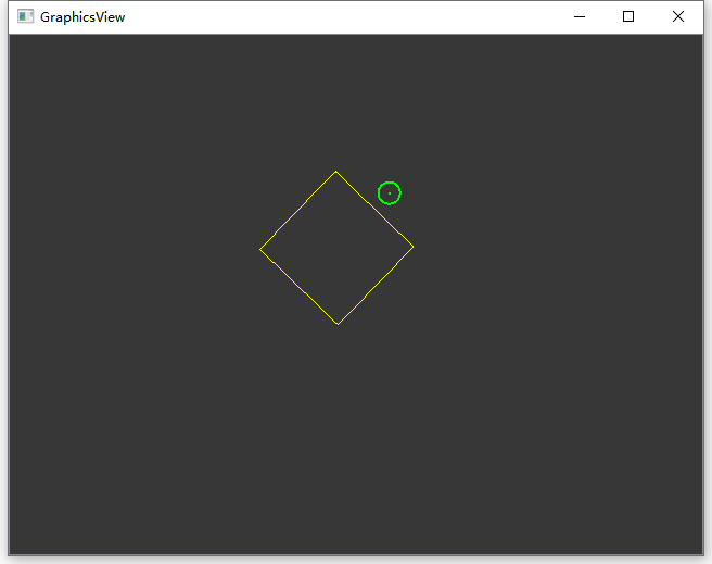
其实要实现绘制、拖动、缩放矩形都不难,难的是在旋转之后还要支持缩放。
我的思路是:
1.实现绘制矩形:只要定义一个全局变量QRectF m_oldRect,在外面矩形大小传进来,然后在paint函数里面绘制这个矩形就行
2.实现拖动矩形:重写mousePressEvent,mouseMoveEvent,mouseReleaseEvent,记录鼠标按下的起始点和移动时候的点,并用moveBy()函数来移动矩形即可
3.实现缩放:在矩形内部靠近4条边的地方定义4个矩形,当鼠标按下的时候在这4个矩形方框内,则将矩形往4个方向拉伸
4.实现旋转:
我给之前定义的矩形全部配一个QPolygonF,因为我只能通过绘制多边形的方式来画出旋转之后的矩形。
矩形正上方的圆圈我是通过三角函数+直线方程来计算,让其始终绘制在矩形左右两个顶点的中垂线上方。
当鼠标落在圆形内部的时候可以控制矩形旋转。
在矩形旋转之后,再进行拉伸的时候,我是通过的计算鼠标的点离对面的边的距离来重新计算矩形的大小,然后计算对应的QPolygonF的大小。
5、GraphicsView坐标系统
Graphics View坐标系基于笛卡尔坐标系,图元的场景中的位置和几何形状通过x坐标和y坐标表示。当使用没有变换的视图观察场景时,场景中的一个单位对应屏幕上的一个像素。
Graphics View架构中有三个有效的坐标系统,图元坐标、场景坐标和视图坐标。Graphics View提供了三个坐标系统之间的转换函数。在绘制图形时,QGraphics View的场景坐标对应QPainter的逻辑坐标,QGraphics View的视图坐标对应QPainter的设备坐标。
5.1 图元坐标
图元存在于自己的本地坐标上,图元的坐标系统通常以图元中心为原点,图元中心也是所有坐标变换的原点,图元坐标方向是x轴正方向向右,y轴正方向向下。创建自定义图元时,只需要注意图元的坐标,QGraphicsScene和QGraphicsView会完成所有的变换。 例如,如果接受到一个鼠标按下或拖入事件,所给的事件位置是基于图元坐标系的。如果某个点位于图元内部,使用图元上的点作为QGraphicsItem::contains()虚函数的参数,函数会返回true。类似,图元的边界矩形和形状也是基于图元坐标系。
图元的位置是图元的中心点在其父图元坐标系统的坐标。按这种说法,场景是所有无父图元的图元的父图元。顶层图元的位置是场景坐标。

子图元的坐标与父图元的坐标相关。如果子图元无变换,子图元坐标和父图元坐标之间的区别与他们的父图元的坐标相同。例如,如果一个无变换的子图元精确的位于父图元的中心点,父子图元的坐标系统是相同的。如果子图元的位置是(10,0),子图元上的点(0,10)就是父图元上的点(10,10)。
由于图元的位置和变换与父图元相关,但子图元的坐标并不会被父图元的变换影响,虽然父图元的变换会隐式地变换子图元。在上例中,即使父图元被翻转和缩放,子图元上的点(0,10)仍旧是父图元上的点(10,10)。
如果调用QGraphicsItem类的paint()函数重绘图元时,则以图元坐标系为基准。
5.2 场景坐标
场景坐标是所有图元的基础坐标系统。场景坐标系统描述了顶层图元的位置,并且构成从视图传播到场景的所有场景事件的基础。每个图元在场景上都有场景坐标和边界矩形。场景坐标的原点在场景中心,坐标原点是X轴正方向向右,Y轴正方向向下。

5.3 视图坐标
视图坐标是窗口部件的坐标,视图坐标的单位是像素,QGraphicsView的左上角是(0,0)。所有鼠标事件、拖拽事件最开始都使用视图坐标,为了和图元交互,需要转换坐标为场景坐标。

5.4 坐标变换
在Graphics View框架中,经常需要将多种坐标变换,从场景到图元,从图元到图元,从视图到场景 。QGraphics View框架坐标变换函数如下:
| 映射函数 | 描述 |
|---|---|
| QGraphicsView::mapToScene() | 从视图坐标系统映射到场景坐标系统 |
| QGraphicsView::mapFromScene() | 从场景坐标系统映射到视图坐标系统 |
| QGraphicsItem::mapToScene() | 从图形项的坐标系统映射到场景的坐标系统 |
| QGraphicsItem::mapFromScene() | 从场景的坐标系统映射到图形项的坐标系统 |
| QGraphicsItem::mapToParent() | 从本图形的坐标系统映射到其父图形的坐标系统 |
| QGraphicsItem::mapFromParent() | 从父图形项的坐标系统映射到本图形项的坐标系统 |
| QGraphicsItem::mapToItem() | 从本图形项的坐标系统映射到另一个图形项的坐标系统 |
| QGraphicsItem::mapFromScene() | 从另一个图形项的坐标系统映射到本图形项的坐标系统 |
在场景中处理图元时,从场景到图元、从图元到图元、从视图到场景进行坐标和图形变换是有用的。当在QGraphicsView的视口中点击鼠标时,应该通过调用QGraphicsView::mapToScence()与QGraphicsScene::itemAt()来获知光标下是场景中的哪个图元;如果想获知一个图元位于视口中的位置,应该先在图元上调用QGraphicsItem::mapToScene(),然后调用QGraphicsView::mapFromScene();如果想获知在一个视图椭圆中有哪些图元,应该把QPainterPath传递到mapToScene(),然后再把映射后的路径传递到QGraphicsScene::items()。 可以调用QGraphicsItem::mapToScene()与QGraphicsItem::mapFromScene()在图元与场景之间进行坐标与形状的映射,也可以在子图元与其父图元之间通过QGraphicsItem::mapToParent()与QGraphicsItem::mapFromItem()进行映射。所有映射函数可以包括点、矩形、多边形、路径。视图与场景之间的映射也与此类似。对于视图与图元之间的映射,应该先从视图映射到场景,然后再从场景图映射到图元。
6、GraphicsView框架特性
1、缩放与旋转
QGraphicsView通过QGraphicsView::setMatrix()支持同QPainter一样的坐标变换,通过对一个视图应用变换,可以很容易地支持普通的导航特性如缩放与旋转。
2、打印
图形视图架构通过渲染函数QGraphicsScene::render()和QGraphicsView::render()支持单行打印
场景和视图的渲染函数的不同在于QGraphicsScene::render()使用场景坐标,QGraphicsView::render()使用视图坐标。QGraphicsScene::render()经常用于打印未变换场景中的整块,例如一块图形数据或是打印一个文本文档。 QGraphicsView::render()适合用于截屏,默认会使用绘图设备精确渲染视口的内容。
QGraphicsScene scene;

scene.addRect(QRectF(0, 0, 100, 200), QPen(Qt::black), QBrush(Qt::green));

QPixmap pixmap;

QPainter painter(&pixmap);

painter.setRenderHint(QPainter::Antialiasing);

scene.render(&painter);

painter.end();

pixmap.save("scene.png");
当源和目标区尺寸不匹配时,源的内容会比例缩放适合目标区。
3、拖拽
由于QGraphicsView继承自QWidget,GraphicsView同样提供了拖拽功能。此外,为了方便,GraphicsView框架也为场景、图元提供拖拽支持。当视图接收到拖拽事件,GraphicsView框架会将拖拽事件翻译为QGraphicsSceneDragDropEvent事件,再发送到场景,场景接管事件,再把事件发送到光标下接受拖拽的第一个图元。
为了开启图元拖拽,创建一个QDrag对象,传递启动拖拽的QWidget的指针。图元可以同时被多个视图观察,但只有一个视图可以拖拽图元。通常,拖拽是从按下鼠标或是移动鼠标开始的,在mousePressEvent()或mouseMoveEvent()中,可以从事件中得到原始的QWidget指针。
void CustomItem::mousePressEvent(QGraphicsSceneMouseEvent *event)
{
    QMimeData *data = new QMimeData;
    data->setColor(Qt::green);
    QDrag *drag = new QDrag(event->widget());
    drag->setMimeData(data);
    drag->start();
}
要在场景中取拖拽事件,需要重新实现QGraphicsScene::dragEnterEvent()和QGraphicsItem子类里特定场景需要的事件处理器。
图元也可以通过调用QGraphicsItem::setAcceptDrops()获得拖拽支持,为了处理将要进行的拖拽,需要重新实现QGraphicsItem的dragEnterEvent()、dragMoveEvent()、dropEvent()、dragLeaveEvent() 。
4、光标与工具提示
QGraphicsItem支持光标(QgraphicsItem::setCursor)与工具提示(QGraphicsItem::setToolTip())。当光标进入到图元的区域,光标与工具提示被QGraphicsView激活(通过调用QGraphicsItem::contains()检测),也可以直接在视图上设置一个缺省光标(QGraphicsView::setCursor)。
5、动画
GraphicsView框架支持多种层次的动画。使用动画框架可以很容易制作出动画。
GraphicsView框架支持的动画实现种类如下:
A、图元需要继承自QGraphicsObject,并且需要联结QPropertyAnimation属性。
B、创建继承自QObject和QGraphicsItem的图元,图元可以设置自己的定时器,在QObject::timeEvent()中增加步进的方式来控制动画。
C、通过调用QGraphicsScene::advance()来推进场景,依次调用QGraphicsItem::advance()。
6、OpenGL渲染
为了使用OpenGL渲染,需要设置一个新的QGLWidget作为QGraphicsView的视口:
QGraphicsView::setViewPort()如果需要OpenGL提供反锯齿功能,则需要OpenGL采样缓冲支持。
1 QGraphicsView view(&scene);
2 view.setViewport(new QGLWidget(QGLFormat(QGL::SampleBuffers)));
7、图元组
通过把一个图元做为另一个图元的孩子,可以得到图元组的大多数本质特性:所有图元会一起移动,所有变换会从父到子传递。
另外,QGraphicsItemGroup是一个特殊的图元。为了增加和删除图元,它使用一个有用接口合并了子图元的事件处理。把一个图元加到QGraphicsItemGroup仍会保留图元的原始位置与变换,而给一个图元重新指定父图元则会让图元根据其新的父亲重新定位。可以用QGraphicsScene::createItemGroup()创建图元组。
8、图形组件和布局
QT4.4通过QGraphicsWidget支持图形和图元布局。QGraphicsWidget类似于QWidget,但QGraphicsWidget并不从QPaintDevice继承,而是继承自QGraphicsItem。QGraphicsWidget支持事件、信号与槽、大小和策略。通过QGraphicsLinearLayout、QGraphicsGridLayout可以对图形组件进行布局管理。
QGraphicsWidget继承了QWidget和QGraphicsItem的优点,如QWidget的样式、字体、调色板、布局方向以及QGraphicsItem的图形、独立精度和变换支持。
QGraphicsLayout是专为QGraphicsWidget特殊设计的第二代布局框架。QGraphicsLayout的API类似于QLayout。通过QGraphicsLinearLayout和QGraphicsGridLayout可以管理组件与子布局。
9、嵌入组件
图形视图框架为嵌入任何组件到场景提供了无缝支持。可以嵌入简单的组件,如QLineEdit、QPushButton,或是复杂的组件如QTableWidget,甚至是主窗口。
要嵌入组件到场景,只需要调用QGraphicsScene::addWidget(),或是创建一个QGraphicsProxyWidget实例,手动嵌入组件。
通过QGraphicsProxyWidget,图形视图框架可以深度整合客户组件特性,如光标、工具提示、鼠标、平板和键盘事件、子组件、动画、弹拉框、组件输入焦点和激活。QGraphicsProxyWidget甚至整合了嵌入组件的tab顺序,可以通过tab选择嵌入的组件。甚至可以嵌入一个QGraphicsView到场景。
当变换和嵌入组件时,图形视图框架会确保组件会被独立变换。
========================================
原文链接:https://www.cnblogs.com/ybqjymy/p/14931414.html

 浙公网安备 33010602011771号