

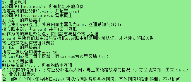
一、拓扑图如下
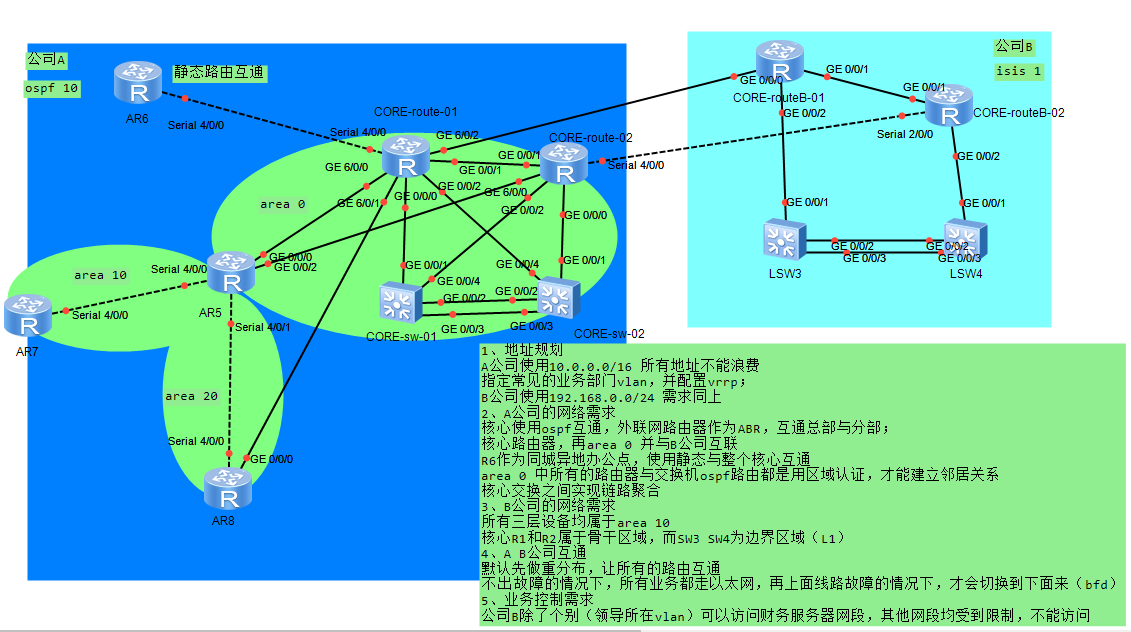
需求:
二、需求的具体配置
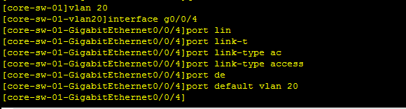
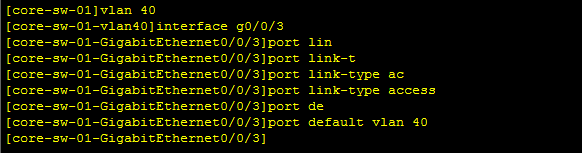
1.配置A公司的业务部门vlan
-------划分vlan----------
vlan10

vlan20
vlan30

vlan40
vlan50
vlan60
---------配置vlan网段-------------
vlan10(sw1)

vlan20(sw1)

vlan30(sw1)

vlan40(sw1)

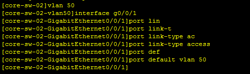
-------vlan50(sw2)---------

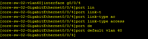
vlan60(sw2)

-------vrrp配置--------------
sw1
开启vlan10vrrp功能

开启vlan20vrrp功能

开启vlan30vrrp功能

开启vlan40vrrp功能

-------sw2------开启vrrp功能
vlan50

vlan60

-------1.1配置B公司部门vlan---------
vlan10
vlan20

vlan30

vlan40
----------配置vlan网段-----------
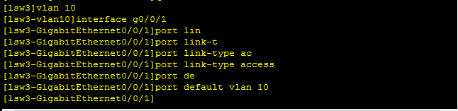
vlan10(sw3)

vlan20(sw3)

vlan30(sw3)

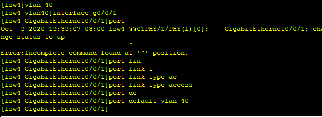
vlan40(sw4)

------vrrp配置--------
sw3
开启vlan10vrrp功能
#
vrrp vrid 10 virtual-ip 192.168.1.10

开启vlan20vrrp功能
#
vrrp vrid 20 virtual-ip 192.168.2.10

开启vlan30vrrp功能
#
vrrp vrid 30 virtual-ip 192.168.3.10

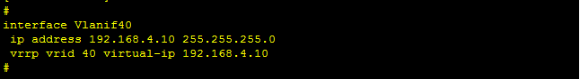
------sw4-----开启vrrp功能
#
vrrp vrid 40 virtual-ip 192.168.4.10
2.配置A公司网络所需要的需求
2.1核心使用ospf互通,外联网路由器为ABR,互通总部与分部
--------核心路由互通------
core-route-01(ip与回环的配置)
#
interface GigabitEthernet0/0/1
ip address 10.12.12.1 255.255.0.0
#

#
interface GigabitEthernet0/0/2
ip address 10.6.6.1 255.255.0.0
#

#
interface GigabitEthernet0/0/0
ip address 10.1.1.1 255.255.0.0
#

#
interface GigabitEthernet6/0/1
ip address 10.18.18.1 255.255.0.0
#

#
interface GigabitEthernet6/0/0
ip address 10.15.15.1 255.255.0.0
#

#
interface Serial4/0/0
link-protocol ppp
ip address 10.16.16.1 255.255.0.0
#

#
interface GigabitEthernet6/0/2
ip address 10.101.101.1 255.255.0.0
#

------ 回环--------
#
interface LoopBack1
ip address 1.1.1.1 255.255.0.0
#

--------core-route-02--------ip与回环的配置
#
interface GigabitEthernet0/0/1
ip address 10.12.12.2 255.255.0.0
#

#
interface GigabitEthernet6/0/0
ip address 10.25.25.2 255.255.0.0
#

#
interface GigabitEthernet0/0/2
ip address 10.21.21.2 255.255.0.0
#

#
interface GigabitEthernet0/0/0
ip address 10.5.5.2 255.255.0.0
#

interface Serial4/0/0
link-protocol ppp
ip address 10.202.202.2 255.255.0.0
#

--------回环----------
#
interface LoopBack1
ip address 2.2.2.2 255.255.0.0
#

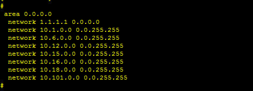
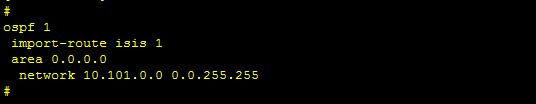
------core-route-01------ospf的划分以及接口回环的ip宣告
#
area 0.0.0.0
network 1.1.1.1 0.0.0.0
network 10.1.0.0 0.0.255.255
network 10.6.0.0 0.0.255.255
network 10.12.0.0 0.0.255.255
network 10.15.0.0 0.0.255.255
network 10.16.0.0 0.0.255.255
network 10.18.0.0 0.0.255.255
network 10.101.0.0 0.0.255.255
#
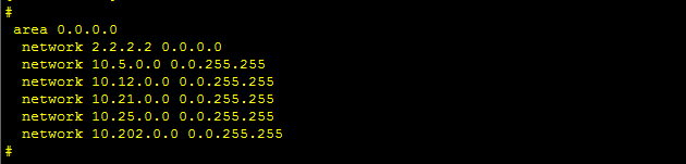
------core-route-02------ospf的划分以及接口回环的ip宣告
#
area 0.0.0.0
network 2.2.2.2 0.0.0.0
network 10.5.0.0 0.0.255.255
network 10.12.0.0 0.0.255.255
network 10.21.0.0 0.0.255.255
network 10.25.0.0 0.0.255.255
network 10.202.0.0 0.0.255.255
#
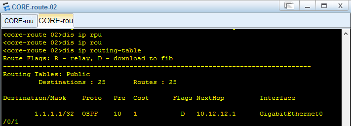
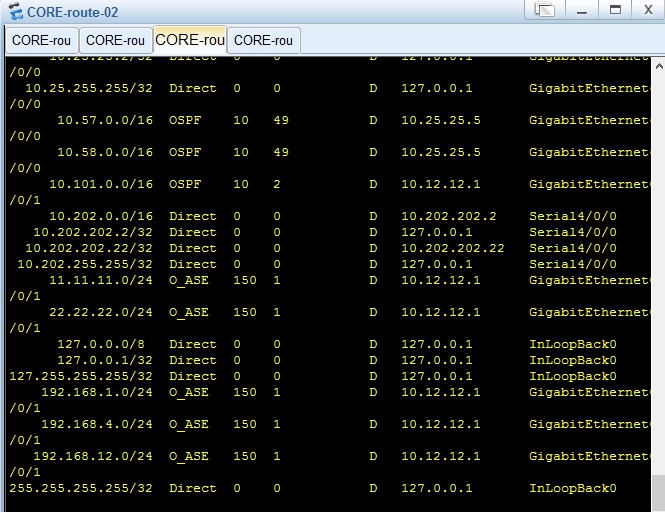
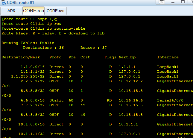
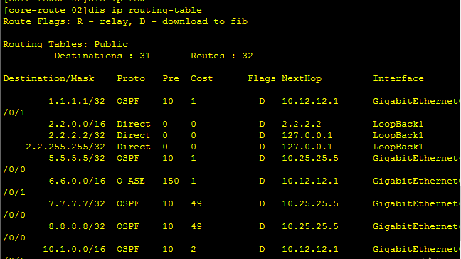
测试发现核心路由1上有核心2的回环ip
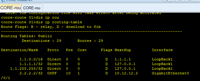
测试发现核心路由2上有核心1的回环ip互通成功
---------ABR配置(R5)-----------
回环、接口ip的配置
#
interface GigabitEthernet0/0/0
ip address 10.15.15.5 255.255.0.0
#

#
interface GigabitEthernet0/0/2
ip address 10.25.25.5 255.255.0.0
#

#
interface Serial4/0/0
link-protocol ppp
ip address 10.57.57.5 255.255.0.0
#

#
interface Serial4/0/1
link-protocol ppp
ip address 10.58.58.5 255.255.0.0
#

-------回环---------
#
interface LoopBack1
ip address 5.5.5.5 255.255.0.0
#

--------R7-----------外部部分
#
interface Serial4/0/0
link-protocol ppp
ip address 10.57.57.7 255.255.0.0
#

回环
#
interface LoopBack1
ip address 7.7.7.7 255.255.0.0
#

-----------R8-----------外部部分
#
interface GigabitEthernet0/0/0
ip address 10.18.18.8 255.255.0.0
#

#
interface Serial4/0/0
link-protocol ppp
ip address 10.58.58.8 255.255.0.0
#

回环
#
interface LoopBack1
ip address 8.8.8.8 255.255.0.0
#

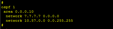
--------R7接口与回环的宣告------------ospf区域划分
#
ospf 1
area 0.0.0.10
network 7.7.7.7 0.0.0.0
network 10.57.0.0 0.0.255.255
#
--------------R8接口ip与回环的宣告--------ospf区域划分
#
area 0.0.0.20
network 8.8.8.8 0.0.0.0
network 10.18.0.0 0.0.255.255
network 10.58.0.0 0.0.255.255
#

----------R5接口ip以及回环的宣告-------各个接口划分于各个ospf接口达到路由互通
#
area 0.0.0.0
network 5.5.5.5 0.0.0.0
network 10.15.0.0 0.0.255.255
network 10.25.0.0 0.0.255.255
#

#
area 0.0.0.10
network 10.57.0.0 0.0.255.255
#

#
area 0.0.0.20
network 10.58.0.0 0.0.255.255
#

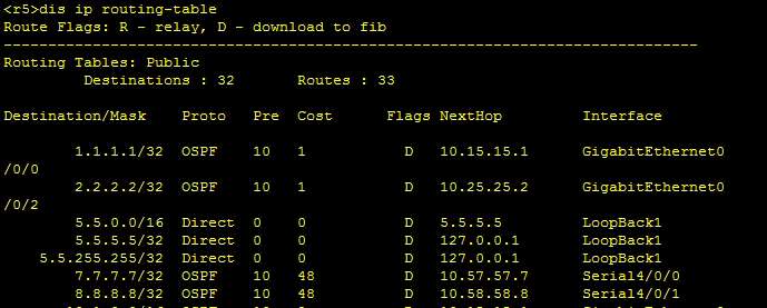
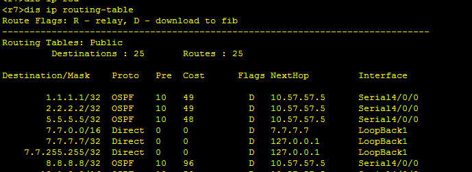
进行测试查看路由表
--------R5----------
---------R7----------------
---------R8--------------
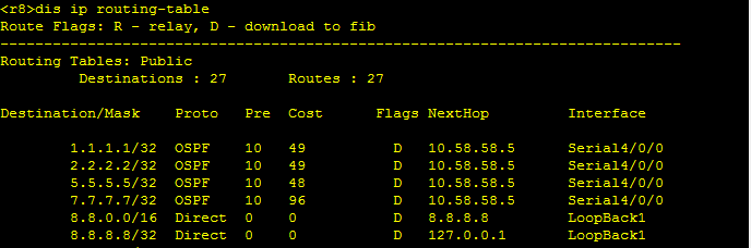
全部互通成功
--------------A公司核心路由与B公司互通-----------------
在B公司中进行isis的配置及ospf和isis的重分布
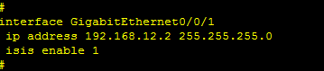
--------核心路由(core-routeB-01)-------将接口加入isis中
#
interface GigabitEthernet0/0/0
ip address 10.101.101.11 255.255.0.0
isis enable 1
#

#
interface GigabitEthernet0/0/1
ip address 192.168.12.1 255.255.255.0
isis enable 1
#

#
interface GigabitEthernet0/0/2
ip address 192.168.1.1 255.255.255.0
isis enable 1
#

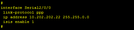
------核心路由(core-routB-02)-----将接口加入isis中
#
interface GigabitEthernet0/0/1
ip address 192.168.12.2 255.255.255.0
isis enable 1
#
#
interface Serial2/0/0
link-protocol ppp
ip address 10.202.202.22 255.255.0.0
isis enable 1
#
#
interface GigabitEthernet0/0/2
ip address 192.168.4.2 255.255.255.0
isis enable 1
#

--------在core-routeB-01上进行isis与ospf的重分布----
#
ospf 1
import-route isis 1

#
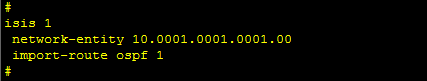
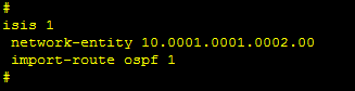
isis 1
network-entity 10.0001.0001.0001.00
import-route ospf 1
#
--------在core-routeB-02上进行isis与ospf的重分布----
#
ospf 1
import-route isis 1
#

#
isis 1
network-entity 10.0001.0001.0002.00
import-route ospf 1
#
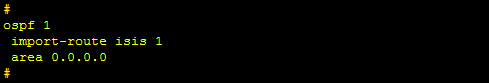
-------在A公司进行ospf与isis的重分布--------
core-route-01
#
ospf 1
import-route isis 1

#
isis 1
import-route ospf 1 
----core-route-02-----
#
ospf 1
import-route isis 1

#
isis 1
import-route ospf 1 
进行测试
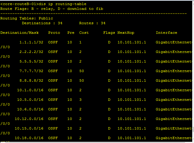
------core-routB-01------
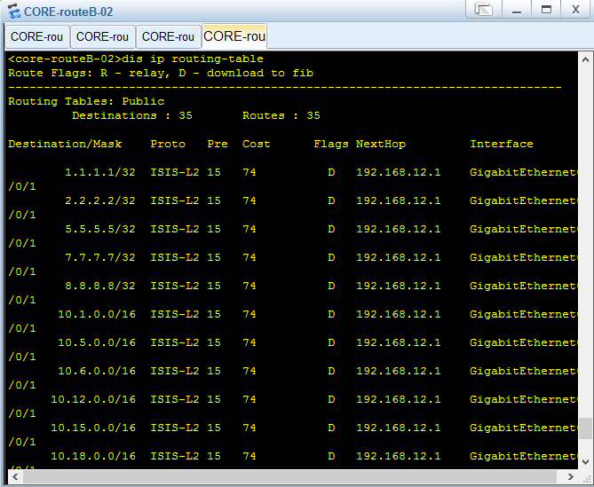
------core-routeB-02------
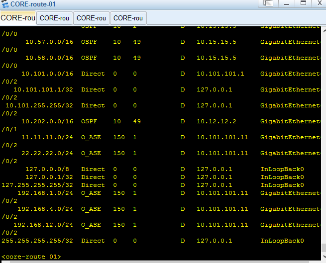
-----core-route-01----A公司
-----core-route-02----A公司
-----core-rout-2----A
-----core-rout-1----A
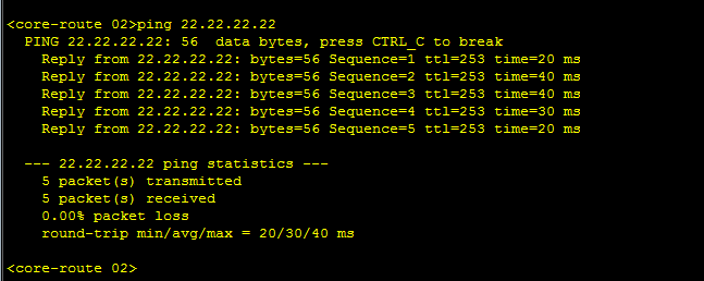
A公司的核心路由与B公司互通 全部互通成功!!
------------------AR6作为同城异地办公地点使用静态与整个核心互通-------------------------------
-----R6的接口与回环的配置---------
#
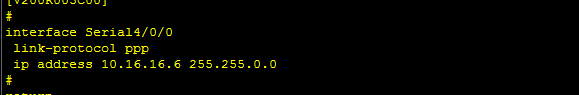
interface Serial4/0/0
link-protocol ppp
ip address 10.16.16.6 255.255.0.0
#
回环
#
interface LoopBack1
ip address 6.6.6.6 255.255.0.0
#

--------在R6上进行静态路由的下一跳互通-----------
#
ip route-static 0.0.0.0 0.0.0.0 10.16.16.1

---------在core-route-01上进行静态路由的互通-----------
ip route-static 6.6.6.6 255.255.0.0 10.16.16.6

--------在core-route01上进行ospf与静态的重分布--------
#
ospf 1
import-route static

-------在R6上测试--------
ping核心01

ping核心02
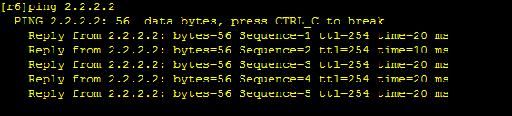
-------在核心R1上测试--------发现R6
-------------在核心R2上测试---------------发现R6
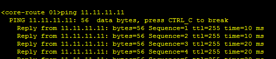
R6与核心总部互通成功(静态路由重分布成功)
--------area0中所有的路由器与交换机ospf路由都是区域认证,才能建立邻居关系---------
(还未写) (还未写) (还未写) (还未写)!!!!!!!!!!!!
-------------核心交换之间实现链路聚合---------
首先将核心交换机core-sw-01中的g0/0/2的端口以及g0/0/3的端口所有vlan配置删除
undo port default vlan
undo port link-type
---------其次进行ethtrunk的配置---------core-sw1
#
interface Eth-Trunk1
mode lacp-static(接入静态lacp)
#

其次将g0/0/2接口加入eth-trunk1中
#
interface GigabitEthernet0/0/2
eth-trunk 1
#

将g0/0/3接口加入eth-trunk1中
#
interface GigabitEthernet0/0/3
eth-trunk 1
#

--------在core-sw2上进行链路聚合的配置-------ethtrunk的配置
首先和核心sw1一样删除接口的所有配置如果有配置过的话!
#
interface Eth-Trunk1
mode lacp-static
#

-----将g0/0/2接口加入ethtrunk1中-----sw2
#
interface GigabitEthernet0/0/2
eth-trunk 1
#

-------将g0/0/3接口加入ethtrunk1中------sw2
#
interface GigabitEthernet0/0/3
eth-trunk 1
#

---------------进行测试--------sw1
#dis eth-trunk 1
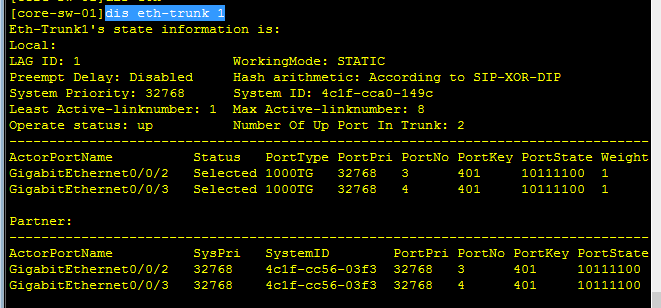
---------进行测试------sw2
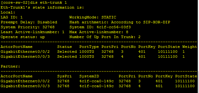
核心交换间的链路聚合成功 !!!!
-------------------B公司的需求----------------
所有三层设备均属于area10(在这里我划分到了area0区域中),核心R1和R2属于骨干区域,而sw3和sw4属于边界区域(L1)
-------core-route-b01-----
#
ospf 1
area 0.0.0.0
-------core-route-b02-----
#
ospf 1
area 0.0.0.0
还有很多未完待续。。。。。。。。。。。。。。

 浙公网安备 33010602011771号