[原创].串行ADC TLC549读取实验,Verilog版本
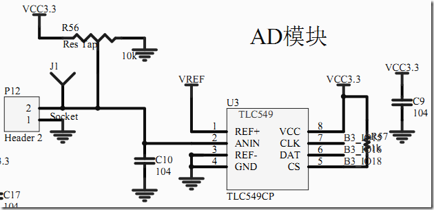
原理图
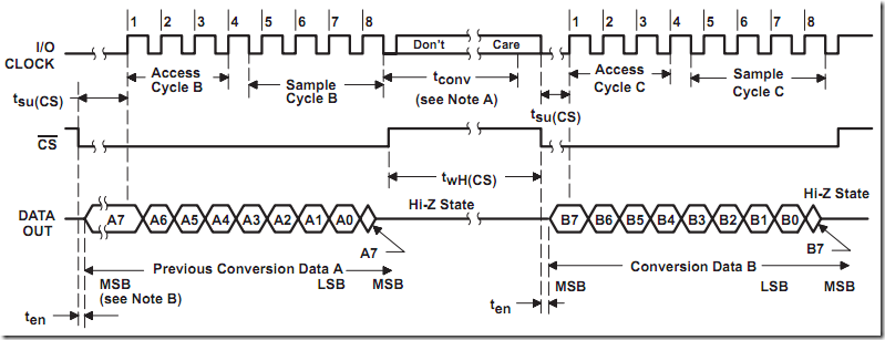
时序图
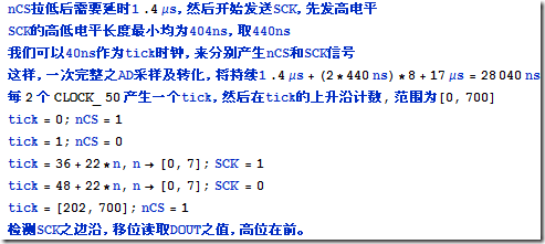
笔记
源代码
顶层文件
module tlc_549_test(
  input  CLOCK_50, // 板载50MHz时钟
  input  RST_N,
  //
  output ADC549_CLK,
  output ADC549_CS_N,
  input ADC549_DATA,
  //
  output [7:0] SEG7_SEG, // 七段数码管 段脚
  output [7:0] SEG7_DIG  // 七段数码管 位脚
);

wire [7:0] ad_data;
tlc549_driver tlc549_driver_inst(
    .CLOCK_50(CLOCK_50),
    .RST_N(RST_N),
    //
    .ad_enable(1'b1),
    .ad_data(ad_data),
    //
    .nCS(ADC549_CS_N),
    .SCK(ADC549_CLK),
    .SDO(ADC549_DATA)
);

seg7x8_drive u0(
  .i_clk            (CLOCK_50),
  .i_rst_n          (RST_N),

  .i_turn_off       (8'b1111_1100), // 熄灭位[2进制]
  .i_dp             (8'b0000_0000), // 小数点位[2进制]
  .i_data           (ad_data), // 欲显数据[16进制]

  .o_seg            (SEG7_SEG),
  .o_dig            (SEG7_DIG)
);

endmodule
数码管驱动http://www.cnblogs.com/yuphone/archive/2011/04/24/2026318.html
TLC549驱动
module tlc549_driver
(
    input CLOCK_50,
    input RST_N,
    //
    input ad_enable,
    output reg [7:0] ad_data,
    //
    output reg nCS,
    output reg SCK,
    input SDO
);

function integer log2(input integer n);
    integer i;
    for(i=0; 2**i <=n; i=i+1) log2=i+1;
endfunction

/**************************************
* 生成40ns的tick时钟
**************************************/
reg cnt_40ns;
always@(posedge CLOCK_50) cnt_40ns <= cnt_40ns + 1'b1;
wire tick_40ns = (cnt_40ns == 1'b1) ? 1 : 0;

/**************************************
* 根据tick时钟生成ad基准计数器
**************************************/
reg [log2(700):1] ad_ref_cnt; // [0,700]
always@(posedge CLOCK_50, negedge RST_N)
    if(!RST_N) ad_ref_cnt <= 0;
    else begin
        if(!ad_enable) ad_ref_cnt <= 0;
        else begin
            if(tick_40ns) begin
                if(ad_ref_cnt < 700)
                    ad_ref_cnt <= ad_ref_cnt + 1'b1;
                else ad_ref_cnt <= 0;
            end
        end
    end

/**************************************
* 根据基准计数器生成串行信号
**************************************/
reg samping_flag; // 采样标志
always@(posedge CLOCK_50, negedge RST_N)
    if(!RST_N) begin
        nCS <= 1;
        SCK <= 0;
        samping_flag <= 0;
    end
    else begin
        if(tick_40ns) begin
            case(ad_ref_cnt)
                // 采样期
                36,58,80,102,124,146,168,190 : SCK <= 1;
                48,70,92,114,136,158,180,202 : SCK <= 0;
                default : ; // 缺省不操作
            endcase
            case(ad_ref_cnt)
                0 : nCS <= 1;
                1 : nCS <= 0;
                // 转换期
                202: nCS <= 1;
                default : ; // 缺省不操作
            endcase
            case(ad_ref_cnt)
                0 : samping_flag <= 0;
                // 采样期
                36 : samping_flag <= 1;
                // 转换期
                202: samping_flag <= 0;
                default : ; // 缺省不操作
            endcase
        end
    end
wire samping_end = (ad_ref_cnt == 202) ? 1 : 0; // 采样结束标志

/**************************************
* 根据串行信号读取串行样本数据
**************************************/
reg [7:0] sample_data;
always@(posedge SCK, negedge RST_N)
    if(!RST_N) sample_data <= {8{1'b0}};
    else begin
        if(SCK) begin
            if (samping_flag != 0) begin
                sample_data[7:1] <= sample_data[6:0];
                sample_data[0] <= SDO;
            end
        end
    end

always@(posedge CLOCK_50, negedge RST_N)
    if(!RST_N) ad_data <= {8{1'b0}};
    else begin
        if (samping_end)
            ad_data <= sample_data;
        else ad_data <= ad_data;
    end

endmodule
Signaltap硬件仿真


 浙公网安备 33010602011771号