
实用指南:OSPF综合大实验
OSPF综合大实验
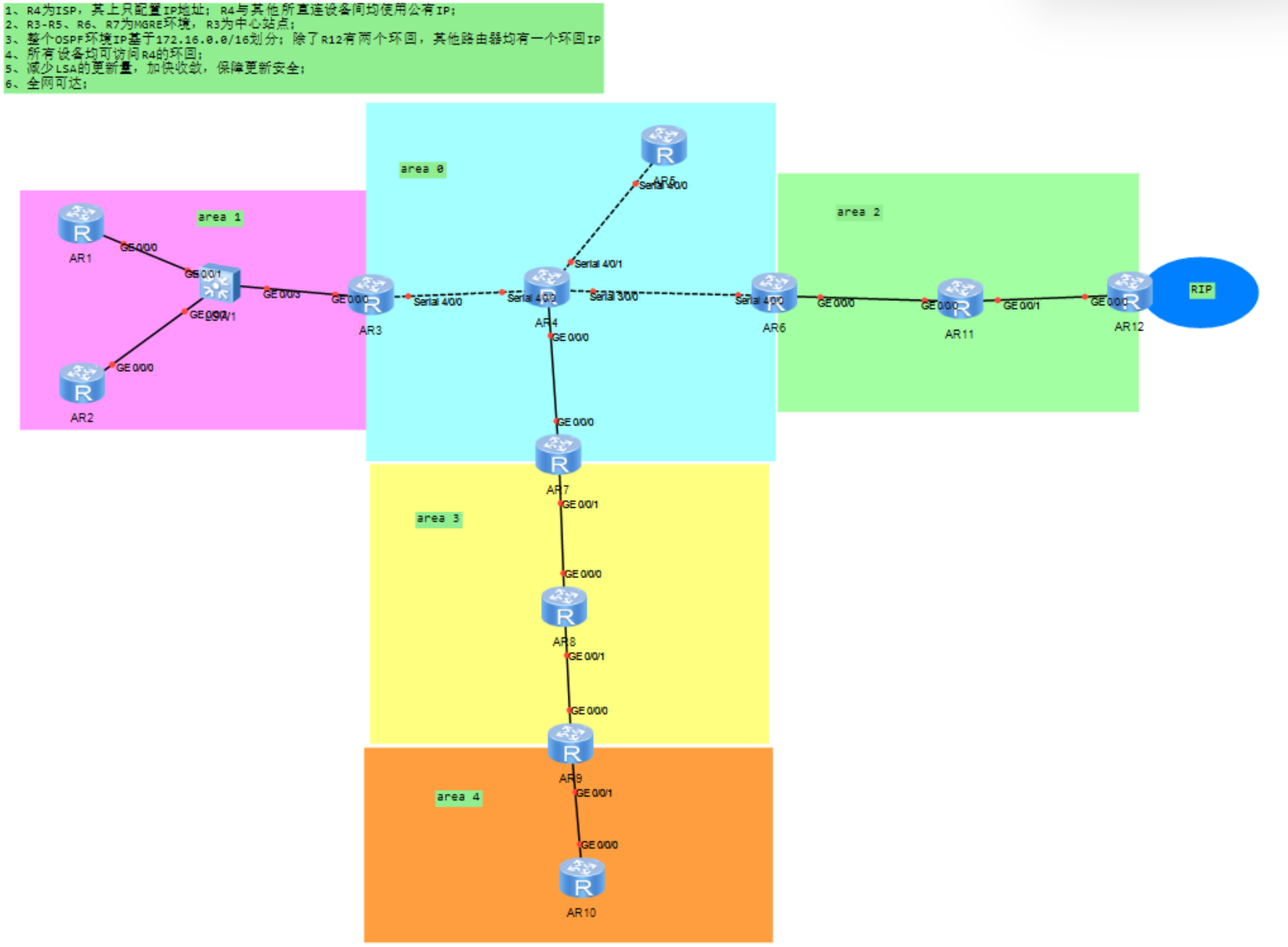
一、实验拓扑
二、实验需求
1、R4为ISP,其上只配置IP地址;R4与其他所直连设备间均使用公有IP;
2、R3-R5、R6、R7为MGRE环境,R3为中心站点;
3、整个OSPF环境IP基于172.16.0.0/16划分;除了R12有两个环回,其他路由器均有一个环回IP
4、所有设备均可访问R4的环回;
5、减少LSA的更新量,加快收敛,保障更新安全;
6、全网可达;
三、实验思路
1.根据网络拓扑,进行网段合理划分;
(1)先根据区域划分(图中一共有五个区域)加上一个RIP,172.16.0.0/16网段先向主机位借3位,划分成8个网段,取前6段:
172.16.0000 0000.0/19 172.16.0.0/19
172.16.0010 0000.0/19 172.16.32.0/19
172.16.0100 0000.0/19 172.16.64.0/19
172.16.0110 0000.0/19 172.16.96.0/19
172.16.1000 0000.0/19 172.16.128.0/19
172.16.1010 0000.0/19 172.16.160.0/19
172.16.1100 0000.0/19
172.16.1110 0000.0/19
(2)area 0:172.16.0.0/19,存在6个广播域(算上R4和R5的环回),再划分成6段,主机位借3位.取前6段,再另外取一网段分配给MGRE
172.16.0000 0000.0/22 172.16.0.0/22
172.16.0000 0100.0/22 172.16.4.0/22
172.16.0000 1000.0/22 172.16.8.0/22
172.16.0000 1100.0/22 172.16.12.0/22
172.16.0001 0000.0/22 172.16.16.0/22
172.16.0001 0100.0/22 172.16.20.0/22
172.16.0001 1000.0/22------隧道网段 172.16.24,0/22
172.16.0001 1100.0/22
(3)area 1:172.16.32.0/19,加上三个环回一共4个广播域,主机位借两位
172.16.0010 0000.0/21 172.16.32.0/21
172.16.0010 1000.0/21 172.16.40.0/21
172.16.0011 0000.0/21 172.16.48.0/21
172.16.0011 1000.0/21 172.16.56.0/21
(4)area 2:172.16.64.0/19,加上三个环回一共5个广播域,主机位借3位,取前五段
172.16.0100 0000.0/22172.16.64.0/22
172.16.0100 0100.0/22172.16.68.0/22
172.16.0100 1000.0/22172.16.72.0/22
172.16.0100 1100.0/22172.16.76.0/22
172.16.0101 0000.0/22172.16.80.0/22
172.16.0101 0100.0/22
172.16.0101 1000.0/22
172.16.0101 1100.0/22
(5)area 3:172.16.96.0/19,加上两个环回一共4个广播域。主机位借两位
172.16.0110 0000.0/21 172.16.96.0/21
172.16.0110 1000.0/21 172.16.104/21
172.16.0111 0000.0/21 172.16.112.0/21
172.16.0111 1000.0/21 172.16.120.0/21
(6)area 4 :172.16.128.0/19,加上一个环回一共3个广播域,主机位借2位
172.16.1000 0000.0/20 172.16.128.0/21
172.16.1000 1000.0/20 172.16.136.0/21
172.16.1001 0000.0/20 172.16.144.0/21
172.16.1001 1000.0/20 172.16.152.0/21
2.根据划分的网段对路由器各接口进行IP地址配置;
3,先把公网整通,然后配置ospf
4.配置MGRE
5.为了减少LSA的更新量,加快收敛,需手工进行ospf的路由汇总
6.同时为了保证更新安全,需配置认证
四、实验步骤
1.根据思路中划分的网段进行路由器接口的IP地址部署
R1:
[R1]int g0/0/0
[R1-GigabitEthernet0/0/0]ip add 172.16.32.1 21
Jul 30 2025 22:07:23-08:00 R1 %%01IFNET/4/LINK_STATE(l)[0]:The line protocol IP
on the interface GigabitEthernet0/0/0 has entered the UP state.
[R1-GigabitEthernet0/0/0]int l0
[R1-LoopBack0]ip add 172.16.40.1 21
R2:
[R2]int g0/0/0
[R2-GigabitEthernet0/0/0]ip add 172.16.32.2 21
[R2-GigabitEthernet0/0/0]
Jul 30 2025 22:09:29-08:00 R2 %%01IFNET/4/LINK_STATE(l)[0]:The line protocol IP
on the interface GigabitEthernet0/0/0 has entered the UP state.
[R2-GigabitEthernet0/0/0]int l0
[R2-LoopBack0]ip add 172.16.48.1 21
R3:
[R3]int g0/0/0
[R3-GigabitEthernet0/0/0]ip add 172.16.32.3 21
Jul 30 2025 22:11:03-08:00 R3 %%01IFNET/4/LINK_STATE(l)[0]:The line protocol IP
on the interface GigabitEthernet0/0/0 has entered the UP state.
[R3-GigabitEthernet0/0/0]int l0
[R3-LoopBack0]ip add 172.16.56.1 21[R3-LoopBack0]int s4/0/0
[R3-Serial4/0/0]ip add 172.16.0.1 22
R4:
[R4]int g0/0/0
[R4-GigabitEthernet0/0/0]ip add 172.16.12.1 22
Jul 30 2025 22:14:21-08:00 R4 %%01IFNET/4/LINK_STATE(l)[0]:The line protocol IP
on the interface GigabitEthernet0/0/0 has entered the UP state.
[R4-GigabitEthernet0/0/0]int s3/0/0
[R4-Serial3/0/0]ip add 172.16.8.1 22
[R4-Serial3/0/0]int s4/0/0
[R4-Serial4/0/0]ip add 172.16.0.2 22
[R4-Serial4/0/0]
Jul 30 2025 22:15:52-08:00 R4 %%01IFNET/4/LINK_STATE(l)[1]:The line protocol PPP
IPCP on the interface Serial4/0/0 has entered the UP state.
[R4-Serial4/0/0]int s4/0/1
[R4-Serial4/0/1]ip add 172.16.4.1 22
[R4-Serial4/0/1]int l0
[R4-LoopBack0]ip add 172.16.16.1 22
R5:
[R5]int s4/0/0
[R5-Serial4/0/0]ip add 172.16.4.2 22
[R5-Serial4/0/0]
Jul 30 2025 22:18:06-08:00 R5 %%01IFNET/4/LINK_STATE(l)[0]:The line protocol PPP
IPCP on the interface Serial4/0/0 has entered the UP state.
[R5-Serial4/0/0]int l0
[R5-LoopBack0]ip add 172.16.20.1 22
R6:
[R6]int s4/0/0
[R6-Serial4/0/0]ip add 172.16.8.2 22
[R6-Serial4/0/0]
Jul 30 2025 22:19:58-08:00 R6 %%01IFNET/4/LINK_STATE(l)[0]:The line protocol PPP
IPCP on the interface Serial4/0/0 has entered the UP state.
[R6-Serial4/0/0]int g0/0/0
[R6-GigabitEthernet0/0/0]ip add 172.16.64.1 22
Jul 30 2025 22:20:32-08:00 R6 %%01IFNET/4/LINK_STATE(l)[1]:The line protocol IP
on the interface GigabitEthernet0/0/0 has entered the UP state.
[R6-GigabitEthernet0/0/0]int l0
[R6-LoopBack0]ip add 172.16.72.1 22
R7:
[R7]int g0/0/0
[R7-GigabitEthernet0/0/0]ip add 172.16.12.2 22
Jul 30 2025 22:22:22-08:00 R7 %%01IFNET/4/LINK_STATE(l)[0]:The line protocol IP
on the interface GigabitEthernet0/0/0 has entered the UP state.
[R7-GigabitEthernet0/0/0]int g0/0/1
[R7-GigabitEthernet0/0/1]ip add 172.16.96.1 21
Jul 30 2025 22:23:05-08:00 R7 %%01IFNET/4/LINK_STATE(l)[1]:The line protocol IP
on the interface GigabitEthernet0/0/1 has entered the UP state.
[R7-GigabitEthernet0/0/1]int l0
[R7-LoopBack0]ip add 172.16.112.1 21
R8:
[R8]int g0/0/0
[R8-GigabitEthernet0/0/0]ip add 172.16.96.2 21
Jul 30 2025 22:24:49-08:00 R8 %%01IFNET/4/LINK_STATE(l)[0]:The line protocol IP
on the interface GigabitEthernet0/0/0 has entered the UP state.
[R8-GigabitEthernet0/0/0]int g0/0/1
[R8-GigabitEthernet0/0/1]ip add 172.16.104.1 21
Jul 30 2025 22:25:36-08:00 R8 %%01IFNET/4/LINK_STATE(l)[1]:The line protocol IP
on the interface GigabitEthernet0/0/1 has entered the UP state.
[R8-GigabitEthernet0/0/1]int l0
[R8-LoopBack0]ip add 172.16.120.1 21
R9:
[R9]int g0/0/0
[R9-GigabitEthernet0/0/0]ip add 172.16.104.2 21
Jul 30 2025 22:27:22-08:00 R9 %%01IFNET/4/LINK_STATE(l)[0]:The line protocol IP
on the interface GigabitEthernet0/0/0 has entered the UP state.
[R9-GigabitEthernet0/0/0]int g0/0/1
[R9-GigabitEthernet0/0/1]ip add 172.16.128.1 21[R9]int l0
[R9-LoopBack0]ip add 172.16.136.1 21
R10:
[R10]int g0/0/0
[R10-GigabitEthernet0/0/0]ip add 172.16.128.2 21
Jul 30 2025 22:42:24-08:00 R10 %%01IFNET/4/LINK_STATE(l)[0]:The line protocol IP
on the interface GigabitEthernet0/0/0 has entered the UP state.
[R10-GigabitEthernet0/0/0]int l0
[R10-LoopBack0]ip add 172.16.144.1 21
R11:
[R11]int g0/0/0
[R11-GigabitEthernet0/0/0]ip add 172.16.64.2 22
Jul 30 2025 22:44:50-08:00 R11 %%01IFNET/4/LINK_STATE(l)[0]:The line protocol IP
on the interface GigabitEthernet0/0/0 has entered the UP state.
[R11-GigabitEthernet0/0/0]int g0/0/1
[R11-GigabitEthernet0/0/1]ip add 172.16.68.1 22
Jul 30 2025 22:45:13-08:00 R11 %%01IFNET/4/LINK_STATE(l)[1]:The line protocol IP
on the interface GigabitEthernet0/0/1 has entered the UP state.
[R11-GigabitEthernet0/0/1]int l0
[R11-LoopBack0]ip add 172.16.76.1 22
R12:
[R12]int g0/0/0
[R12-GigabitEthernet0/0/0]ip add 172.16.68.2 22
Jul 30 2025 22:47:09-08:00 R12 %%01IFNET/4/LINK_STATE(l)[0]:The line protocol IP
on the interface GigabitEthernet0/0/0 has entered the UP state.
[R12-GigabitEthernet0/0/0]int l0
[R12-LoopBack0]ip add 172.16.80.1 22
[R12-LoopBack0]int l2
[R12-LoopBack2]ip add 172.16.160.1 19
2.先将公网整通
在R3,R5,R6,R7上安装静态缺省
R3:
[R3]ip route-static 0.0.0.0 0.0.0.0 172.16.0.2
R5:
[R5]ip route-static 0.0.0.0 0.0.0.0 172.16.4.1
R6:
[R6]ip route-static 0.0.0.0 0.0.0.0 172.16.8.1
R7:
[R7]ip route-static 0.0.0.0 0.0.0.0 172.16.12.1
3.配置OSPF环境,在除R4外所有路由器上开启OSPF
[R1]ospf 1
[R1-ospf-1]area 1
[R1-ospf-1-area-0.0.0.1]network 172.16.32.1 0.0.0.0[R1-ospf-1-area-0.0.0.1]network 172.16.40.1 0.0.0.0
[R2]ospf 1
[R2-ospf-1]area 1
[R2-ospf-1-area-0.0.0.1]network 172.16.32.2 0.0.0.0[R2-ospf-1-area-0.0.0.1]network 172.16.48.1 0.0.0.0
[R3]ospf 1
[R3-ospf-1]area 1
[R3-ospf-1-area-0.0.0.1]network 172.16.32.1 0.0.0.0
[R3-ospf-1-area-0.0.0.1]network 172.16.56.1 0.0.0.0
[R3-ospf-1-area-0.0.0.1]q
[R3-ospf-1]area 0
[R3-ospf-1-area-0.0.0.0]network 172.16.0.1 0.0.0.0
[R5]ospf 1
[R5-ospf-1]area 0
[R5-ospf-1-area-0.0.0.0]network 172.16.20.1 0.0.0.0
[R5-ospf-1-area-0.0.0.0]network 172.16.4.2 0.0.0.0
[R6]ospf 1
[R6-ospf-1]area 0
[R6-ospf-1-area-0.0.0.0]network 172.16.8.2 0.0.0.0
[R6-ospf-1-area-0.0.0.0]q
[R6-ospf-1]area 2
[R6-ospf-1-area-0.0.0.2]network 172.16.64.1 0.0.0.0
[R6-ospf-1-area-0.0.0.2]network 172.16.72.1 0.0.0.0
[R7]ospf 1
[R7-ospf-1]area 0
[R7-ospf-1-area-0.0.0.0]network 172.16.12.2 0.0.0.0
[R7-ospf-1-area-0.0.0.0]q
[R7-ospf-1]area 3
[R7-ospf-1-area-0.0.0.3]network 172.16.112.1 0.0.0.0
[R7-ospf-1-area-0.0.0.3]network 172.16.96.1 0.0.0.0
[R8]ospf 1
[R8-ospf-1]area 3
[R8-ospf-1-area-0.0.0.3]net 172.16.120.1 0.0.0.0
[R8-ospf-1-area-0.0.0.3]net 172.16.104.1 0.0.0.0
[R8-ospf-1-area-0.0.0.3]net 172.16.96.2 0.0.0.0
[R9]ospf 1
[R9-ospf-1]area 3
[R9-ospf-1-area-0.0.0.3]net 172.16.104.2 0.0.0.0
[R9-ospf-1-area-0.0.0.3]q
[R9-ospf-1]area 4
[R9-ospf-1-area-0.0.0.4]net 172.16.128.1 0.0.0.0
[R9-ospf-1-area-0.0.0.4]net 172.16.136.1 0.0.0.0
[R10]ospf 1
[R10-ospf-1]area 4
[R10-ospf-1-area-0.0.0.4]net 172.16.128.2 0.0.0.0
[R11]ospf 1
[R11-ospf-1]area 2
[R11-ospf-1-area-0.0.0.2]net 172.16.64.2 0.0.0.0
[R11-ospf-1-area-0.0.0.2]net 172.16.68.1 0.0.0.0
[R11-ospf-1-area-0.0.0.2]net 172.16.76.1 0.0.0.0
[R12]ospf 1
[R12-ospf-1]area 2
[R12-ospf-1-area-0.0.0.2]net 172.16.68.2 0.0.0.0[R12-ospf-1-area-0.0.0.2]net 172.16.80.1 0.0.0.0
4.安装MGRE
R3:
[R3]int tunnel 0/0/0
[R3-Tunnel0/0/0]ip add 172.16.24.1 22
[R3-Tunnel0/0/0]tunnel-protocol gre p2mp
[R3-Tunnel0/0/0]source 172.16.0.1
Aug 1 2025 20:58:08-08:00 R3 %%01IFNET/4/LINK_STATE(l)[0]:The line protocol IP
on the interface Tunnel0/0/0 has entered the UP state.
R5:
[R5]int tunnel 0/0/0
[R5-Tunnel0/0/0]ip add 172.16.24.2 22
[R5-Tunnel0/0/0]tunnel-protocol gre p2mp
[R5-Tunnel0/0/0]source 172.16.4.2
Aug 1 2025 21:02:12-08:00 R5 %%01IFNET/4/LINK_STATE(l)[0]:The line protocol IP
on the interface Tunnel0/0/0 has entered the UP state.
R6:
[R6]int tunnel 0/0/0
[R6-Tunnel0/0/0]ip add 172.16.24.3 22
[R6-Tunnel0/0/0]tunnel-protocol gre p2mp
[R6-Tunnel0/0/0]source 172.16.8.2
Aug 1 2025 21:06:32-08:00 R6 %%01IFNET/4/LINK_STATE(l)[0]:The line protocol IP
on the interface Tunnel0/0/0 has entered the UP state.
R7:
[R7]int tunnel 0/0/0
[R7-Tunnel0/0/0]ip add 172.16.24.4 22
[R7-Tunnel0/0/0]tunnel-protocol gre p2mp
[R7-Tunnel0/0/0]source 172.16.12.2
Aug 1 2025 21:09:43-08:00 R7 %%01IFNET/4/LINK_STATE(l)[0]:The line protocol IP
on the interface Tunnel0/0/0 has entered the UP state.
5.配备NHRP
R3:
R3]int t0/0/0
[R3-Tunnel0/0/0]nhrp network-id 100
R5:
[R5]int t0/0/0
[R5-Tunnel0/0/0]nhrp network-id 100
[R5-Tunnel0/0/0]nhrp entry 172.16.24.1 172.16.0.1
R6:
[R6]int t0/0/0
[R6-Tunnel0/0/0]nhrp network
[R6-Tunnel0/0/0]nhrp network-id 100
[R6-Tunnel0/0/0]nhrp entry 172.16.24.1 172.16.0.1 register
R7:
[R7]int tunnel 0/0/0
[R7-Tunnel0/0/0]nhrp network-id 100
[R7-Tunnel0/0/0]nhrp entry 172.16.24.1 172.16.0.1 re
[R7-Tunnel0/0/0]nhrp entry 172.16.24.1 172.16.0.1 register
6.进行路由汇总,减少LSA
7.更新认证

 浙公网安备 33010602011771号