串口、IIC、中断综合应用练习
串口、IIC、中断综合应用练习
1. 项目要求
- 通过串口下发3组流水灯显示顺序
比如:1.3#3,2#2,1
则有3组流水灯显示顺序: ①led1->led3 ②led3->led2 ③led2->led1 - 当按下按键3的时候,顺序按照3种顺序显示流水灯。
比如: 第1次按下 按照1来显示流水灯
第2次按下 按照2来显示流水灯
第3次按下 按照 3 来显示流水灯
第4次按下 按照1来显示流水灯
2. 功能实现及分析
思维导图:
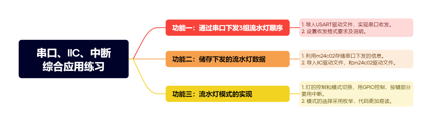
3. 具体实现
灯光控制可以达到项目要求效果,灯光模式串口输出储存到m24c02,然后通过按键控制模式选择
main.c
#include "USART.h"
#include "led.h"
#include "key.h"
#include "delay.h"
#include "m24c02.h"
#include "string.h"
// 定义全局变量
uint16_t leds[] = {LED_green, LED_red, LED_yellow};
uint8_t buffer[100];
uint8_t size;
uint8_t isOver;
// 用二维数组保存三组流水灯方案
uint32_t plans[3][2];
// 定义流水灯方案状态
Plan_Status plan_status = NO_PLANS;
// 声明功能函数
void LoadPlans(uint8_t *str); // 从EEPROM中读取方案
void LedFlow(void); // 流水灯实现
int main()
{
// 1. 初始化
Driver_USART1_Init();
LED_Init();
Delay_ms(500);
// printf("LED初始化完成%p\n", GPIOB->ODR);
KEY_Init();
M24C02_Init();
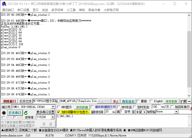
printf("*******串口、IIC、中断综合应用练习*******\n");
// 2.从EEPROM中读取方案
printf("正在从EEPROM读取流水灯方案...\n");
M24C02_ReadBytes(0x00, buffer, 11);
printf("buffer:%s\n", buffer);
LoadPlans(buffer);
while (1)
{
if (isOver)
{
// 保存到EEPROM
M24C02_WriteBytes(0x00, buffer, size);
// 清除标志位和size
size = 0;
isOver = 0;
LoadPlans(buffer);
}
// 根据状态展示流水灯
LedFlow();
}
}
// 解析流水灯方案,并加载到plans里
void LoadPlans(uint8_t *str)
{
// 判断首字符是否为0,如果为0则直接退出
if (!str[0])
{
return;
}
// 指定当前状态为第一组方案
plan_status = P1;
// 解析当前的字符串
sscanf((char *)str, "%d,%d#%d,%d#%d,%d",
&plans[0][0], &plans[0][1],
&plans[1][0], &plans[1][1],
&plans[2][0], &plans[2][1]);
// 将数值转换为对应的LED灯
for (uint8_t i = 0; i < 3; i++)
{
for (uint8_t j = 0; j < 2; j++)
{
switch (plans[i][j])
{
case 1:
plans[i][j] = LED_red;
break;
case 2:
plans[i][j] = LED_yellow;
break;
case 3:
plans[i][j] = LED_green;
break;
default:
break;
}
printf("plans[%d][%d]:%d\n", i, j, plans[i][j]);
}
}
}
// 流水灯实现
void LedFlow(void)
{
printf("plan_status:%d\n", plan_status);
switch (plan_status)
{
case P1:
LED_OffAll(leds, 3);
for (uint8_t i = 0; i < 2; i++)
{
LED_On(plans[0][i]);
Delay_ms(500);
LED_Off(plans[0][i]);
}
break;
case P2:
LED_OffAll(leds, 3);
for (uint8_t i = 0; i < 2; i++)
{
LED_On(plans[1][i]);
Delay_ms(500);
LED_Off(plans[1][i]);
}
break;
case P3:
LED_OffAll(leds, 3);
for (uint8_t i = 0; i < 2; i++)
{
LED_On(plans[2][i]);
Delay_ms(500);
LED_Off(plans[2][i]);
}
break;
default:
printf("plan_status错误\n");
break;
}
}
led.c
/*
 * @Author: Yangyang
 * @Date: 2025-1-16 21:41:00
 * @Description: led驱动函数
 *
 */
#include "led.h"
//========================================================================
/**
 * @name 	LED_Init()
 * @brief	led初始化
 * @param  无
 * @retval 无
 */
//========================================================================
void LED_Init(void)
{
	// 1. 开启对应外设时钟
	RCC->APB2ENR |= RCC_APB2ENR_IOPBEN;

	// 2. 对应GPIO工作模式配置,2MHz输出,开漏

	GPIOB->CRL &= ~GPIO_CRL_CNF7;
	GPIOB->CRL |= GPIO_CRL_MODE7_1;
	GPIOB->CRL &= ~GPIO_CRL_MODE7_0;

	GPIOB->CRL &= ~GPIO_CRL_CNF6;
	GPIOB->CRL |= GPIO_CRL_MODE6_1;
	GPIOB->CRL &= ~GPIO_CRL_MODE6_0;

	GPIOB->CRL &= ~GPIO_CRL_CNF5;
	GPIOB->CRL |= GPIO_CRL_MODE5_1;
	GPIOB->CRL &= ~GPIO_CRL_MODE5_0;

	// 3. 所有灯引脚芯片端输出高电平,默认关灯
	GPIOB->ODR |= GPIO_ODR_ODR7 | GPIO_ODR_ODR6 | GPIO_ODR_ODR5;
}
//========================================================================
/**
 * @name 	LED_On(),LED_Off()
 * @brief	控制led开关
 * @param  	led: led引脚
 * @retval 无
 */
//========================================================================
void LED_On(uint16_t led)
{
	switch (led)
	{
	case LED_red:
		GPIOB->ODR &= ~led;
		break;
	case LED_yellow:
		GPIOB->ODR &= ~led;
		break;
	case LED_green:
		GPIOB->ODR &= ~led;
		break;
	}
}

void LED_Off(uint16_t led)
{
	switch (led)
	{
	case LED_red:
		GPIOB->ODR |= led;
		break;
	case LED_yellow:
		GPIOB->ODR |= led;
		break;
	case LED_green:
		GPIOB->ODR |= led;
		break;
	}
}

// 翻转LED状态
void LED_Toggle(uint16_t led)
{
	// 需要先判断当前LED状态,读取IDR对应位
	if ((GPIOA->IDR & led) == 0)
	{
		LED_Off(led);
	}
	else
	{
		LED_On(led);
	}
}

// 对一组LED灯,全开全关
void LED_OnAll(uint16_t leds[], uint8_t size)
{
	for (uint8_t i = 0; i < size; i++)
	{
		LED_On(leds[i]);
	}
}

void LED_OffAll(uint16_t leds[], uint8_t size)
{
	for (uint8_t i = 0; i < size; i++)
	{
		LED_Off(leds[i]);
	}
}
led.h
#ifndef __LED_H__
#define __LED_H__

#include "stm32f10x.h"

// 宏定义led引脚

#define LED_red GPIO_ODR_ODR7
#define LED_yellow GPIO_ODR_ODR6
#define LED_green GPIO_ODR_ODR5

// 初始化
void LED_Init(void);

// 控制LED亮灭
void LED_On(uint16_t led);
void LED_Off(uint16_t led);

// 翻转LED状态
void LED_Toggle(uint16_t led);

// 对一组LED灯,全开全关
void LED_OnAll(uint16_t leds[], uint8_t size);
void LED_OffAll(uint16_t leds[], uint8_t size);

#endif
key.c
#include "key.h"

void KEY_Init(void)
{
	// 1. 配置时钟
	RCC->APB2ENR |= RCC_APB2ENR_IOPAEN;
	RCC->APB2ENR |= RCC_APB2ENR_AFIOEN;

	// 2. 配置GPIO工作模式和默认输入值
	GPIOA->CRL &= ~GPIO_CRL_MODE7;
	GPIOA->CRL |= GPIO_CRL_CNF7_1;
	GPIOA->CRL &= ~GPIO_CRL_CNF7_0;

	GPIOA->ODR &= ~GPIO_ODR_ODR7;

	// 3. AFIO配置引脚复用选择
	AFIO->EXTICR[2] |= AFIO_EXTICR3_EXTI10_PA;
	AFIO->EXTICR[1] &= ~AFIO_EXTICR2_EXTI7;
	AFIO->EXTICR[1] |= AFIO_EXTICR2_EXTI7_PA;

	// 4. 配置EXTI
	EXTI->RTSR |= EXTI_RTSR_TR7; // 允许线下降沿触发
	EXTI->IMR |= EXTI_IMR_MR7;	 // 允许MR7线的中断请求

	// 5. NVIC配置
	NVIC_SetPriorityGrouping(3); // 全部都是抢占优先级
	NVIC_SetPriority(EXTI9_5_IRQn, 3);
	NVIC_EnableIRQ(EXTI9_5_IRQn);
}

// 中断服务程序
void EXTI9_5_IRQHandler(void)
{
	// 先清除中断挂起标志位
	EXTI->PR |= EXTI_PR_PR7;
	//plan_status = (Plan_Status)((plan_status + 1) % 3);
	// 防抖延迟
	Delay_ms(10);

	if ((GPIOA->IDR & GPIO_IDR_IDR7) != 0)
	{
		plan_status = (Plan_Status)((plan_status + 1) % 3);
	}
}
key.h
#ifndef __KEY_H__
#define __KEY_H__

#include "stm32f10x.h"
#include "delay.h"
#include "led.h"

typedef enum
{
    NO_PLANS = -1,
    P1,
    P2,
    P3
} Plan_Status;

extern Plan_Status plan_status;

void KEY_Init(void);

#endif
usart.c
#include "USART.h"

/**
 * @description: 初始化串口1
 */
void Driver_USART1_Init(void)
{
    /* 1. 开启时钟 */
    /* 1.1 串口1外设的时钟 */
    RCC->APB2ENR |= RCC_APB2ENR_USART1EN;
    /* 1.2 GPIO时钟 */
    RCC->APB2ENR |= RCC_APB2ENR_IOPAEN;

    /* 2. 配置GPIO引脚的工作模式  PA9=Tx(复用推挽 CNF=10 MODE=11)  PA10=Rx(浮空输入 CNF=01 MODE=00)*/
    GPIOA->CRH |= GPIO_CRH_CNF9_1;
    GPIOA->CRH &= ~GPIO_CRH_CNF9_0;
    GPIOA->CRH |= GPIO_CRH_MODE9;

    GPIOA->CRH &= ~GPIO_CRH_CNF10_1;
    GPIOA->CRH |= GPIO_CRH_CNF10_0;
    GPIOA->CRH &= ~GPIO_CRH_MODE10;

    /* 3. 串口的参数配置 */
    /* 3.1 配置波特率 115200 */
    USART1->BRR = 0x271;
    /* 3.2 串口使能,并使能接收和发送 */
    // USART1->CR1 |= USART_CR1_UE;
    USART1->CR1 |= USART_CR1_TE;
    USART1->CR1 |= USART_CR1_RE;
    /* 3.3 配置一个字的长度 8位 */
    USART1->CR1 &= ~USART_CR1_M;
    /* 3.4 配置不需要校验位 */
    USART1->CR1 &= ~USART_CR1_PCE;
    /* 3.5 配置停止位的长度为1个停止位 */
    USART1->CR2 &= ~USART_CR2_STOP;

    /* 3.6 使能串口的各种中断 */
    USART1->CR1 |= USART_CR1_RXNEIE; /* 接收非空中断 */
    USART1->CR1 |= USART_CR1_IDLEIE; /* 空闲中断 */

    /* 4. 配置NVIC */
    /* 4.1 配置优先级组 */
    NVIC_SetPriorityGrouping(3);
    /* 4.2 设置优先级 */
    NVIC_SetPriority(USART1_IRQn, 2);
    /* 4.3 使能串口1的中断 */
    NVIC_EnableIRQ(USART1_IRQn);

    /* 4. 使能串口 */
    USART1->CR1 |= USART_CR1_UE;
}

/**
 * @description: 发送一个字节
 * @param {uint8_t} byte 要发送的字节
 */
void Driver_USART1_SendChar(uint8_t byte)
{
    /* 1. 等待发送寄存器为空 */
    while ((USART1->SR & USART_SR_TXE) == 0)
        ;
    /* 2. 数据写出到数据寄存器 */
    USART1->DR = byte;
}

/**
 * @description: 发送一个字符串
 * @param {uint8_t} *str 要发送的字符串
 * @param {uint16_t} len 字符串中字节的长度
 * @return {*}
 */
void Driver_USART1_SendString(uint8_t *str, uint16_t len)
{
    for (uint16_t i = 0; i < len; i++)
    {
        Driver_USART1_SendChar(str[i]);
    }
}

// /**
//  * @description: 接收一个字节的数据
//  * @return {*} 接收到的字节
//  */
// uint8_t Driver_USART1_ReceiveChar(void)
// {
//     /* 等待数据寄存器非空 */
//     while ((USART1->SR & USART_SR_RXNE) == 0)
//         ;
//     return USART1->DR;
// }

// /**
//  * @description: 接收变长数据.接收到的数据存入到buff中
//  * @param {uint8_t} buff 存放接收到的数据
//  * @param {uint8_t} *len 存放收到的数据的字节的长度
//  */
// void Driver_USART1_ReceiveString(uint8_t buff[], uint8_t *len)
// {
//     uint8_t i = 0;
//     while (1)
//     {
//         // 等待接收非空
//         while ((USART1->SR & USART_SR_RXNE) == 0)
//         {
//             // 在等待期间, 判断是否收到空闲帧
//             if (USART1->SR & USART_SR_IDLE)
//             {
//                 *len = i;
//                 return;
//             }
//         }
//         buff[i] = USART1->DR;
//         i++;
//     }
// }

// 中断服务程序
void USART1_IRQHandler(void)
{
    if ((USART1->SR & USART_SR_RXNE))
    {
        // 接收到一个字符,就放入缓冲区
        buffer[size++] = USART1->DR;
    }
    else if ((USART1->SR & USART_SR_IDLE))
    {
        // 字符串接收完毕,置位标志位,清除IDLE
        USART1->DR;
        isOver = 1;
    }
}
// 重写putchar,用于printf重定向
int fputc(int c, FILE *file)
{
    Driver_USART1_SendChar(c);
    return c;
}
usart.h
#ifndef __USART_H__
#define __USART_H__

#include "stm32f10x.h"
#include "stdio.h"

extern uint8_t buffer[100];
extern uint8_t size;
extern uint8_t isOver;

void Driver_USART1_Init(void);

void Driver_USART1_SendChar(uint8_t byte);

void Driver_USART1_SendString(uint8_t *str, uint16_t len);

// uint8_t Driver_USART1_ReceiveChar(void);

// void Driver_USART1_ReceiveString(uint8_t buff[], uint8_t *len);

#endif
iic.c
#include "iic.h"

// 初始化
void I2C_Init(void)
{
    // 1. 配置时钟
    RCC->APB2ENR |= RCC_APB2ENR_IOPBEN;
    RCC->APB1ENR |= RCC_APB1ENR_I2C2EN;

    // 2. GPIO工作模式配置:复用开漏输出 CNF-11,MODE-11
    GPIOB->CRH |= (GPIO_CRH_MODE10 | GPIO_CRH_MODE11 |
                   GPIO_CRH_CNF10 | GPIO_CRH_CNF11);

    // 3. I2C2配置
    // 3.1 硬件工作模式
    I2C2->CR1 &= ~I2C_CR1_SMBUS;
    I2C2->CCR &= ~I2C_CCR_FS;

    // 3.2 选择输入的时钟频率
    I2C2->CR2 |= 36;

    // 3.3 配置CCR,对应数据传输速率100kb/s,SCL高电平时间为 5us
    I2C2->CCR |= 180;

    // 3.4 配置TRISE,SCL上升沿最大时钟周期数 + 1
    I2C2->TRISE |= 37;

    // 3.5 使能I2C2模块
    I2C2->CR1 |= I2C_CR1_PE;
}

// 发出起始信号
uint8_t I2C_Start(void)
{
    // 产生一个起始信号
    I2C2->CR1 |= I2C_CR1_START;

    // 引入一个超时时间
    uint16_t timeout = 0xffff;

    // 等待起始信号发出
    while ((I2C2->SR1 & I2C_SR1_SB) == 0 && timeout)
    {
        timeout--;
    }
    return timeout ? OK : FAIL;
}

// 设置接收完成之后发出停止信号
void I2C_Stop(void)
{
    I2C2->CR1 |= I2C_CR1_STOP;
}

// 主机设置使能应答信号
void I2C_Ack(void)
{
    I2C2->CR1 |= I2C_CR1_ACK;
}

// 主机设置使能非应答信号
void I2C_Nack(void)
{
    I2C2->CR1 &= ~I2C_CR1_ACK;
}

// 主机发送设备地址,并等待应答
uint8_t I2C_SendAddr(uint8_t addr)
{
    // 直接将要发送的地址给到DR
    I2C2->DR = addr;

    // 等待应答
    uint16_t timeout = 0xffff;
    while ((I2C2->SR1 & I2C_SR1_ADDR) == 0 && timeout)
    {
        timeout--;
    }
    // 访问SR2,清除ADDR标志位
    if (timeout > 0)
    {
        I2C2->SR2;
    }

    return timeout ? OK : FAIL;
}

// 主机发送一个字节的数据(写入),并等待应答
uint8_t I2C_SendByte(uint8_t byte)
{
    // 1. 先等待DR为空,上一个字节数据已经发送完毕
    uint16_t timeout = 0xffff;
    while ((I2C2->SR1 & I2C_SR1_TXE) == 0 && timeout)
    {
        timeout--;
    }

    // 2. 将要发送的字节放入DR中
    I2C2->DR = byte;

    // 3. 等待应答
    timeout = 0xffff;
    while ((I2C2->SR1 & I2C_SR1_BTF) == 0 && timeout)
    {
        timeout--;
    }
    return timeout ? OK : FAIL;
}

// 主机从EEPROM接收一个字节的数据(读取)
uint8_t I2C_ReadByte(void)
{
    // 1. 先等待DR为满
    uint16_t timeout = 0xffff;
    while ((I2C2->SR1 & I2C_SR1_RXNE) == 0 && timeout)
    {
        timeout--;
    }

    // 2. 将收到的字节数据返回
    return timeout ? I2C2->DR : FAIL;
}
iic.h
#ifndef __IIC_H
#define __IIC_H

#include "stm32f10x.h"
#include "delay.h"

// 宏定义
#define OK 0
#define FAIL 1

// 初始化
void I2C_Init(void);

// 发出起始信号
uint8_t I2C_Start(void);

// 设置发出停止信号
void I2C_Stop(void);

// 主机设置使能应答信号
void I2C_Ack(void);

// 主机设置使能非应答信号
void I2C_Nack(void);

// 主机发送设备地址,并等待应答
uint8_t I2C_SendAddr(uint8_t addr);

// 主机发送一个字节的数据(写入),并等待应答
uint8_t I2C_SendByte(uint8_t byte);

// 主机从EEPROM接收一个字节的数据(读取)
uint8_t I2C_ReadByte(void);

#endif
m24c02.c
#include "m24c02.h"

// 初始化
void M24C02_Init(void)
{
    I2C_Init();
}

// 向EEPROM写入一个字节
void M24C02_WriteByte(uint8_t innerAddr, uint8_t byte)
{
    // 1. 发出开始信号
    I2C_Start();

    // 2. 发送写地址
    I2C_SendAddr(W_ADDR);

    // 3. 发送内部地址
    I2C_SendByte(innerAddr);

    // 4. 发送具体数据
    I2C_SendByte(byte);

    // 5. 发出一个停止信号
    I2C_Stop();

    // 延迟等待写入周期结束
    Delay_ms(5);
}

// 读取EEPROM的一个字节
uint8_t M24C02_ReadByte(uint8_t innerAddr)
{
    // 1. 发出开始信号
    I2C_Start();

    // 2. 发送写地址(假写)
    I2C_SendAddr(W_ADDR);

    // 3. 发送内部地址
    I2C_SendByte(innerAddr);

    // 4. 发出开始信号
    I2C_Start();

    // 5. 发送读地址(真读)
    I2C_SendAddr(R_ADDR);

    // 6. 设置非应答
    I2C_Nack();

    // 7. 设置在接收下一个字节后发出停止信号
    I2C_Stop();

    // 8. 读取一个字节
    uint8_t byte = I2C_ReadByte();

    return byte;
}

// 连续写入多个字节(页写)
void M24C02_WriteBytes(uint8_t innerAddr, uint8_t *bytes, uint8_t size)
{
    // 1. 发出开始信号
    I2C_Start();

    // 2. 发送写地址
    I2C_SendAddr(W_ADDR);

    // 3. 发送内部地址
    I2C_SendByte(innerAddr);

    // 利用循环不停发送数据
    for (uint8_t i = 0; i < size; i++)
    {
        // 4. 发送具体数据
        I2C_SendByte(bytes[i]);
    }

    // 5. 发出一个停止信号
    I2C_Stop();

    // 延迟等待写入周期结束
    Delay_ms(5);
}

// 连续读取多个字节
void M24C02_ReadBytes(uint8_t innerAddr, uint8_t *buffer, uint8_t size)
{
    // 1. 发出开始信号
    I2C_Start();

    // 2. 发送写地址(假写)
    I2C_SendAddr(W_ADDR);

    // 3. 发送内部地址
    I2C_SendByte(innerAddr);

    // 4. 发出开始信号
    I2C_Start();

    // 5. 发送读地址(真读)
    I2C_SendAddr(R_ADDR);

    // 利用循环连续读取多个字节
    for (uint8_t i = 0; i < size; i++)
    {
        // 6. 设置应答或非应答
        if (i < size - 1)
        {
            I2C_Ack();
        }
        else
        {
            I2C_Nack();

            // 7. 设置发出停止信号
            I2C_Stop();
        }
        // 8. 读取一个字节
        buffer[i] = I2C_ReadByte();
    }
}
m24c02.h
#ifndef __M24C02_H
#define __M24C02_H

#include "iic.h"

// 宏定义
#define W_ADDR 0xA0
#define R_ADDR 0xA1

// 初始化
void M24C02_Init(void);

// 向EEPROM写入一个字节
void M24C02_WriteByte(uint8_t innerAddr, uint8_t byte);

// 读取EEPROM的一个字节
uint8_t M24C02_ReadByte(uint8_t innerAddr);

// 连续写入多个字节(页写)
void M24C02_WriteBytes(uint8_t innerAddr, uint8_t * bytes, uint8_t size);

// 连续读取多个字节
void M24C02_ReadBytes(uint8_t innerAddr, uint8_t * buffer, uint8_t size);

#endif
delay.c
#include "delay.h"

// 延时函数,微秒作为单位,利用系统嘀嗒定时器,72MHz,一次嘀嗒 1/72 us
void Delay_us(uint16_t us)
{
	// 1. 装载一个计数值,72 * us
	SysTick->LOAD = 72 * us;

	// 2. 配置,使用系统时钟(1),计数结束不产生中断(0),使能定时器(1)
	SysTick->CTRL = 0x05;

	// 3. 等待计数值变为0,判断CTRL标志位COUNTFLAG是否为1
	while ((SysTick->CTRL & SysTick_CTRL_COUNTFLAG) == 0)
	{}

	// 4. 关闭定时器
	// SysTick->CTRL &= ~SysTick_CTRL_ENABLE;
}

void Delay_ms(uint16_t ms)
{
	while (ms--)
	{
		Delay_us(1000);
	}
}

void Delay_s(uint16_t s)
{
	while (s--)
	{
		Delay_ms(1000);
	}
}
delay.h
#ifndef __DELAY_H
#define __DELAY_H

#include "stm32f10x.h"

void Delay_us(uint16_t us);
void Delay_ms(uint16_t ms);
void Delay_s(uint16_t s);

#endif

 浙公网安备 33010602011771号