


S3C2440串口的基本使用
2440A有三个串口,我们使用串口0对它进行了解熟悉。
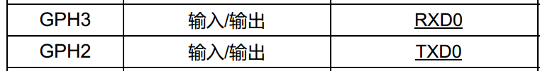
首先肯定是应该找到手册上串口0所对应的引脚,然后配置相应寄存器。
串口0对应GPIO H的 2,3
串口在单片机中我们已经有很多使用经验了,对于协议采用 8-N-1,8bit数据位,无校验,1停止位。
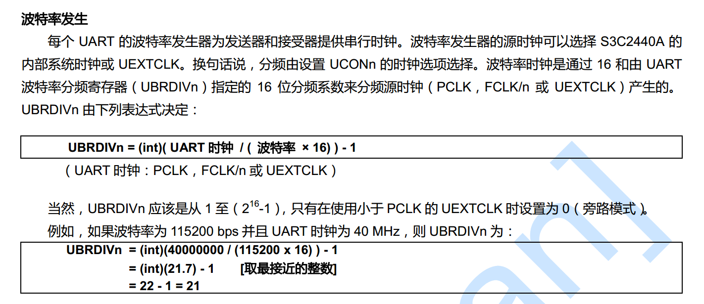
说明波特率的计算方式:

把串口对应IO配置成 TX和RX功能之后,我们需要对指定寄存器进行读写操作,实现串口的接发。
具体的寄存器就不贴出来了。手册上都有,这里不使用FIFO和中断方式,只是最基本的接发操作。
main.c:
#include "s3c2440_gpio.h"
#include "s3c2440_soc.h"
#include "uart.h"

void SystemInit(void)
{
    //配置LOCKTIME(0x4C000000) = 0xFFFFFFFF
    *(volatile unsigned int *)0x4C000000=0xFFFFFFFF;
    //CLKDIVN(0x4C000014) = 0X5, tFCLK:tHCLK:tPCLK = 1:4:8
    *(volatile unsigned int *)0x4C000014=0x5;
    //协处理指令
    __asm__(
    "mrc    p15, 0, r1, c1, c0, 0\n"        /* 读出控制寄存器 */
    "orr    r1, r1, #0xc0000000\n"          /* 设置为“asynchronous bus mode” */
    "mcr    p15, 0, r1, c1, c0, 0\n"        /* 写入控制寄存器 */
    );
    /* 设置MPLLCON(0x4C000004) = (92<<12)|(1<<4)|(1<<0)
     *  m = MDIV+8 = 92+8=100
     *  p = PDIV+2 = 1+2 = 3
     *  s = SDIV = 1
     *  FCLK = 2*m*Fin/(p*2^s) = 2*100*12/(3*2^1)=400M
     */
    *(volatile unsigned int *)0x4C000004=(92<<12)|(1<<4)|(1<<0);
}
void Delay(uint32_t count)
{
    while(count--);
}
int main(void)
{
    //配置GPIOF 0,2,GPIOG 3为输入模式
    Set_gpio(IN, GPIOF,GPIO_PinSource0);
    Set_gpio(IN, GPIOF,GPIO_PinSource2);
    Set_gpio(IN, GPIOG,GPIO_PinSource3);
    //点亮LED1然后熄灭
    Reset_gpio(OUT, GPIOF,GPIO_PinSource4);
    Delay(100000);
    Set_gpio(OUT, GPIOF,GPIO_PinSource4);
    Delay(100000);
    //点亮LED2然后熄灭
    Reset_gpio(OUT, GPIOF,GPIO_PinSource5);
    Delay(100000);
    Set_gpio(OUT, GPIOF,GPIO_PinSource5);
    Delay(100000);
    //点亮LED3然后熄灭
    Reset_gpio(OUT, GPIOF,GPIO_PinSource6);
    Delay(100000);
    Set_gpio(OUT, GPIOF,GPIO_PinSource6);
    Delay(100000);
    //熄灭三盏LED灯
    Set_gpio(OUT, GPIOF,GPIO_PinSource5);
    Set_gpio(OUT, GPIOF,GPIO_PinSource4);

    unsigned char c;

    uart_init();
    puts("Hello, world!\n\r");

    while (1)
    {

        while(1)
        {
            c = getchar();
            if (c == '\r')
            {
                putchar('\n');
            }

            if (c == '\n')
            {
                putchar('\r');
            }

            putchar(c);
        }


    }
    return 0;
}
uart.c:
#include "uart.h"
#include "s3c2440_soc.h"
#define PCLK            50000000    // PCLK为50MHz
#define UART_CLK        PCLK        //  UART0的时钟源设为PCLK
#define UART_BAUD_RATE  115200      // 波特率
#define UART_BRD        ((int)(UART_CLK  / (UART_BAUD_RATE * 16.0)+0.5) - 1)
#define NULL 0
void uart_init(void)
{
    /* GPH2,3用于TxD0, RxD0 */
    //清除GPHCON
    GPHCON &= ~((3<<4) | (3<<6));
    //设置2,3为发送接收
    GPHCON |= ((2<<4) | (2<<6));
    //使能内部上拉
    GPHUP &= ~((1<<2) | (1<<3));
    ULCON0  = 0x03;     // 8N1(8个数据位,无校验,1个停止位)
    UCON0   = 0x05;     // 中断/查询模式,UART时钟源为PCLK
    UFCON0  = 0x00;     // 不使用FIFO
    UMCON0  = 0x00;     // 不使用流控
    UBRDIV0 = UART_BRD; // 波特率为115200

}

int putchar(int c)
{
    /* UTRSTAT0 */
    /* UTXH0 */
    /*发送是向寄存器写数据*/
    while (!(UTRSTAT0 & (1<<2)));
    UTXH0 = (unsigned char)c;
    return 0;

}

int getchar(void)
{
//接收是在寄存器中读数据
    while (!(UTRSTAT0 & (1<<0)));
    return URXH0;
}

int puts(const char *s)
{
    if(s!=NULL)
    {
        while (*s)
        {
            putchar(*s);
            s++;
        }
    }
    return 0;
}
配置串口,要注意波特率,还有是否有缓存,实际应用中,FIFO是不可缺少的,这里只是入门简单实现。
启动文件和之前的时钟章节一样,
Makefile:
all:
    arm-linux-gcc -c -g -o s3c2440_gpio.o s3c2440_gpio.c
    arm-linux-gcc -c -g -o uart.o uart.c
    arm-linux-gcc -c -g -o main.o main.c
    arm-linux-gcc -c -g -o start.o start.S
    arm-linux-ld -Ttext 0 start.o main.o s3c2440_gpio.o uart.o -o uart.elf
    arm-linux-objcopy -O binary -S uart.elf uart.bin
    arm-linux-objdump -S -D uart.elf > uart.dis
clean:
    rm *.bin *.o *.elf *.dis
NOTE:
在此之后,还是不去编写库函数了,太过于消耗时间,使用寄存器配置的方式,如果工作中需要长期使用某个cpu或mcu时,再去编写对应的库函数,因为时间实在不够。
欢迎加入作者的小圈子
扫描下方左边二维码加入QQ交流群,扫描下方右边二维码关注个人微信公众号并获取更多隐藏干货,QQ交流群:816747642 微信公众号:Crystal软件学堂


|
作者:Crystal软件学堂 bilibili视频教程地址:https://space.bilibili.com/5782182 本文版权归作者和博客园共有,欢迎转载,但未经作者同意必须保留此段声明,且在转载文章页面给出原文连接。 如果你觉得文章对你有所帮助,烦请点个推荐,你的支持是我更文的动力。 文中若有错误,请您务必指出,感谢给予我建议并让我提高的你。 |

 浙公网安备 33010602011771号