halcon——缺陷检测常用方法总结(测量拟合)
引言
机器视觉中缺陷检测分为一下几种:
- blob分析+特征
- 模板匹配(定位)+差分:halcon——缺陷检测常用方法总结(模板匹配(定位)+差分) - 唯有自己强大 - 博客园 (cnblogs.com)
- 光度立体:halcon——缺陷检测常用方法总结(光度立体) - 唯有自己强大 - 博客园 (cnblogs.com)
- 特征训练
- 测量拟合
- 频域+空间域结合:halcon——缺陷检测常用方法总结(频域空间域结合) - 唯有自己强大 - 博客园 (cnblogs.com)
- 深度学习
本篇主要总结一下缺陷检测中测量拟合的方法。通过测量被测物的尺寸(长短粗细、高矮胖瘦、间隙宽窄,包括我以前做过的平面度、平行度、轮廓度)等问题来检测产品是否合格。
测量拟合
在产品生产过程中会不可避免的产生尺寸缺陷和表面外观缺陷,前几篇的缺陷着重于表面外观的检测,本篇基于尺寸缺陷检测用测量拟合的方法来实现。
🧡halcon中测量算子分析:
在机器视觉中,测量是必不可少的一个分支。测量主要包括有物体大小的测量、距离的测量以及物体完整度检测等。在工业机器视觉里面常用的有1维测量和2维测量,不过大部分的测量都是要基于标定之后(需要获取环境参数,比如得到pixel的物理大小)不经过标定的测量都只是测量物体的相对大小(像素大小)。
1️⃣维测量:
像点到点的距离,边缘对的距离等沿着一维方向的测量都属于1D测量范畴。Halocn的一维测量的步骤:
- 创建测量矩形或者测量扇形区域(gen_measure_rectangle2,gen_measure_arc)
- 测量单边缘或边缘对(measure_pos,measure_pairs)
- 显示
相关算子:
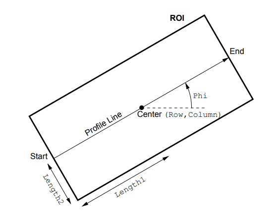
- gen_measure_rectangle2(形成测量矩形)
gen_measure_rectangle2( Row, Column, Phi, Length1, Length2, Width, Height, Interpolation : MeasureHandle)

参数列表:
Row//仿射矩形中心行坐标
Column//仿射矩形中心列坐标
Phi//仿射矩形的纵轴水平角,单位弧度 ,注意:测量矩形的测量方向的选择
Length1//仿射矩形宽度的一半
Length2//仿射矩形高度的一半
Width//图像的宽度
Height//图像的高度
Interpolation //插值类型('bicubic', 'bilinear', 'nearest_neighbor')
MeasureHandle//测量对象句柄
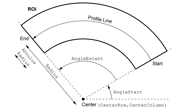
- gen_measure_arc(形成测量扇形)
gen_measure_arc( Row, Col, Radius, AngleStart, AngleExtent, Radius, Width, Height, Interpolation :MeasureHandle)

参数列表:
Row//中心点行坐标
Col//中心点列坐标
AngleStart//起始角度
AngleExtent//角度范围
Radius//半径
Width//图像宽
Height//图像高
Interpolation //插值方法
MeasureHandle//句柄
- measure_pos(测量单边缘)
measure_pos (Image, MeasureHandle, Sigma, Threshold, Transition, Select, RowEdge, ColumnEdge, Amplitude, Distance)

参数列表:
Sigma//高斯平滑系数(图像上可能会有噪点,影响我们对边缘的判断)
Threshold//阈值(代表阈值超过该值把它当做边缘)
Transition//极性
Select//边缘选择
RowEdge//找到的边缘中心的行坐标
ColumnEdge//找到的边缘中心列坐标
Amplitude//边缘幅度
Distance//相邻边缘之间的距离
- measure_pairs(测量边缘对)
measure_pairs(Image ,MeasureHandle, Sigma, Threshold, Transition, Select : RowEdgeFirst, ColumnEdgeFirst, AmplitudeFirst, RowEdgeSecond, ColumnEdgeSecond, AmplitudeSecond, IntraDistance, InterDistance)

参数列表:
Image//输入图像
MeasureHandle//测量对象句柄
Sigma//高斯平滑参数
Threshold最//小边缘幅度
Transition//边缘对极性,
Select //选择边缘对
RowEdgeFirst//边缘点对的第一个边缘的中心行坐标
ColumnEdgeFirst//边缘点对的第一个边缘的中心列坐标
AmplitudeFirst//第一个边缘的幅度
RowEdgeSecond//第二个边缘中心行坐标
ColumnEdgeSecond//第二个边缘中心列坐标
AmplitudeSecond//第二个边缘幅度
IntraDistance//两个边缘对之间的距离
InterDistance//相邻边缘对之间的距离
二者区别:

- translate_measure(转换度量对象)
描述:一般用于一个程序中有很多测量矩形的情况,当使用第二个测量矩形时,不需要重新gen_measure_rectangle2生成,将第二个测量矩形的中心坐标放到该算子的第二、三个参数当中即可。
translate_measure(  MeasureHandle, Row, Column )(选用)

参数列表:
MeasureHandle//测量句柄
Row//新参考点的行坐标
Column //新参考点的列坐标
💚halcon实例分析
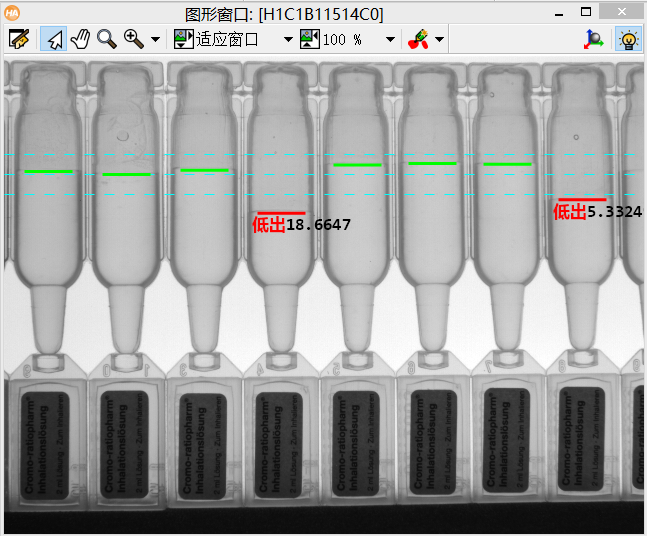
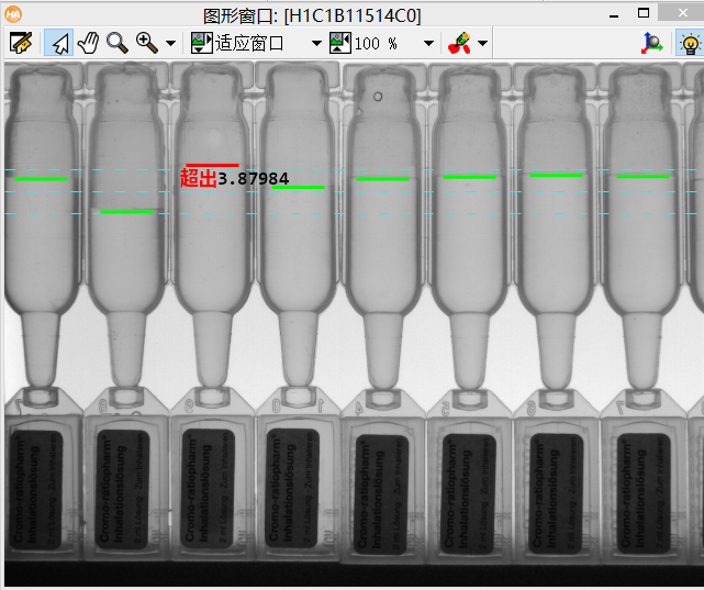
1,测量液体线高度
本案例通过测量矩形测量液位线的位置来判断液体是装多了还是装少了。(测量矩形使用形状模板匹配定位跟随测量)
整体思路:
- 以瓶底为模板进行模板匹配
- 设定标准液线,高液线,低液线(瓶内液体在该范围内判定合格)
- 将测量矩形移动到测量位置进行测量
- 显示
dev_get_window (WindowHandle)
set_display_font (WindowHandle, 15, 'mono', 'true', 'false')
read_image (Image, 'ampoules/ampoules_01')
* 创建模板
get_image_size (Image, Width, Height)
gen_rectangle1 (ModelRegion, 264, 54, 321, 100)
reduce_domain (Image, ModelRegion, TemplateImage)
create_shape_model (TemplateImage, 3, rad(-5), rad(10), 'auto', ['none','no_pregeneration'], 'use_polarity', [25,54,4], 4, ModelID)
get_shape_model_contours (ModelContours, ModelID, 1)
NumImages := 8
for Index := 1 to NumImages by 1
    read_image (Image, 'ampoules/ampoules_' + Index$'.2d')
       * 寻找实例
       find_shape_model (Image, ModelID, rad(-5), rad(10), 0.7, 0, 0.5, 'least_squares', [3,1], 0.75, Row, Column, Angle, Score)
       MeanRows:=mean(Row)
       Length1:=52
       Length2:=20
       gen_measure_rectangle2 (0, 0, rad(90), Length1, Length2,Width, Height, 'nearest_neighbor', MeasureHandle)

       * 设置两条参考线
       MeasureRow:=MeanRows-180
       standard:=120//标准液线
       offset:=20//允许液线偏移量
       RefLineHigh:=standard-offset//高液线
       RefLineLow:=standard+offset//低液线
       dev_set_color ('cyan')

       dev_set_line_width (1)
       set_line_style (WindowHandle, 10)

       gen_contour_polygon_xld (ContourLineHigh, [RefLineHigh,RefLineHigh], [0,Width])
       gen_contour_polygon_xld (ContourLineLow, [RefLineLow,RefLineLow], [0,Width])
       gen_contour_polygon_xld (ContourStand, [standard,standard], [0,Width])
       dev_display (Image)
       dev_display (ContourStand)
       dev_display (ContourLineHigh)
       dev_display (ContourLineLow)
       for I := 0 to |Score| - 1 by 1
              * 将测量矩形移动到测量位置
              dev_set_line_width (3)
              set_line_style (WindowHandle, 0)
              * 转换度量对象
              translate_measure (MeasureHandle, MeasureRow, Column[I])
              measure_pos (Image, MeasureHandle, 2.6, 7, 'all', 'all', RowEdge, ColumnEdge, Amplitude, Distance)
              if(|RowEdge|>0)
                  if(RowEdge<RefLineHigh)
                      dev_set_color ('red')
                     gen_contour_polygon_xld (Contour, [RowEdge,RowEdge], [ColumnEdge-24,ColumnEdge+24])
                     dev_display (Contour)
                     disp_message (WindowHandle, '超出'+(RefLineHigh-RowEdge), 'image', RowEdge, ColumnEdge-30, 'red', 'false')
                  elseif(RowEdge>RefLineLow)
                         dev_set_color ('red')
                          gen_contour_polygon_xld (Contour, [RowEdge,RowEdge], [ColumnEdge-24,ColumnEdge+24])
                         dev_display (Contour)
                         disp_message (WindowHandle, '低出'+(RowEdge-RefLineLow), 'image', RowEdge, ColumnEdge-30, 'red', 'false')
                  else
                          dev_set_color ('green')
                          gen_contour_polygon_xld (Contour, [RowEdge,RowEdge], [ColumnEdge-24,ColumnEdge+24])
                          dev_display (Contour)
                  endif
              endif
       endfor
       stop()
endfor
2,检测矩形通孔的缺陷
如图,该例程是对矩形区域的冲压通孔的缺陷检测,由图可以看到有的区域边缘有缺陷,具体表现就是边缘不齐整,向下突出了一块。
于是我们就自然想到了:提取矩形的实际轮廓xld,再拟合一个标准的轮廓xld,利用dist_rectangle2_contour_points_xld 这个算子求实际轮廓与理论轮廓点对点的距离,只要这个距离超过了我们的设定值,就认为边缘有缺陷了。而且还可以根据距离的大小和超出设定距离的点的数量来评价这个缺陷的严重程度。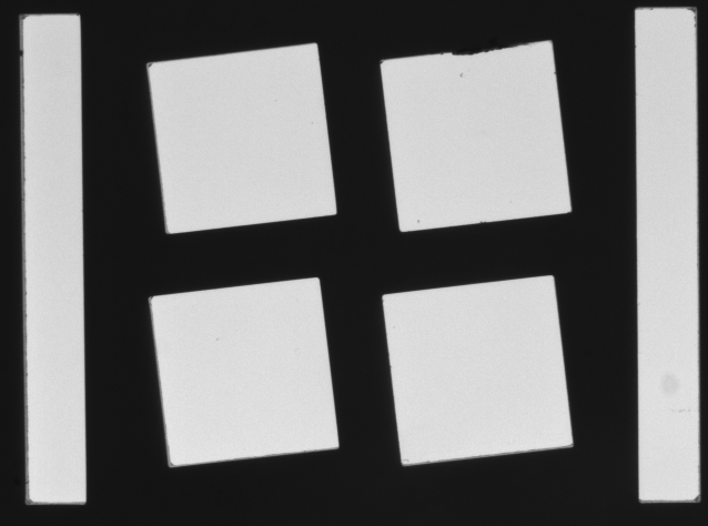
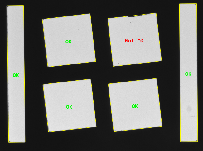
dev_update_off ()
*读入图像
read_image (Image, 'punched_holes')
get_image_size (Image, Width, Height)
dev_close_window ()
dev_open_window (0, 0, Width, Height, 'black', WindowHandle)
set_display_font (WindowHandle, 16, 'mono', 'true', 'false')
dev_display (Image)
*快速二值化(增加了被提取区域最小尺寸10个像素)
fast_threshold (Image, Region, 128, 255, 10)
*形态学求边界,inner代表内边界。内边界=原图-腐蚀后的图,外边界=膨胀后的图-原图
boundary (Region, Border, 'inner')
dilation_rectangle1 (Border, EdgeROI, 7, 7)
*抠图
reduce_domain (Image, EdgeROI, ImageReduced)
*边缘提取,输出XLD轮廓,平滑系数1.7
edges_sub_pix (ImageReduced, Edges, 'canny', 1.7, 40, 120)
* 选择周长在500-100000像素内的边界
select_shape_xld (Edges, RectangleEdges, 'contlength', 'and', 500, 100000)
* 拟合一个矩形的亚像素轮廓xld
fit_rectangle2_contour_xld (RectangleEdges, 'tukey', -1, 0, 0, 3, 2, Row, Column, Phi, Length1, Length2, PointOrder)
* 形成一个矩形的亚像素轮廓xld
gen_rectangle2_contour_xld (Rectangles, Row, Column, Phi, Length1, Length2)
dev_set_color ('yellow')
dev_display (Rectangles)
*计算所有边界的数量
count_obj (RectangleEdges, Number)
*开始计算轮廓上的点和最小外接矩形上的点之间的距离(会排除4个叫的距离)
for I := 0 to Number - 1 by 1
    *开始选中第一个轮廓,索引从1开始
    select_obj (RectangleEdges, RectangleEdge, I + 1)
   *通过轮廓,得到轮廓上的点的坐标。会有很多点,这是实际边界上的点
    get_contour_xld (RectangleEdge, Rows, Cols)
    *形成XLD亚像素轮廓
    gen_rectangle2_contour_xld (Rect, Row[I], Column[I], Phi[I], Length1[I], Length2[I])
   * 获得拟合的轮廓上的点。这是标准矩形上的点
    get_contour_xld (Rect, RowC, ColC)
    *下面是横坐标的平方和+纵坐标的平方和,开跟号
    *求的就是实际边界上的点和拟合矩形边界上的点的距离
    *RowC,ColC从0-3,代表的是拟合的矩形的4个角的坐标值
    D1 := sqrt((Rows - RowC[0]) * (Rows - RowC[0]) + (Cols - ColC[0]) * (Cols - ColC[0]))
    D2 := sqrt((Rows - RowC[1]) * (Rows - RowC[1]) + (Cols - ColC[1]) * (Cols - ColC[1]))
    D3 := sqrt((Rows - RowC[2]) * (Rows - RowC[2]) + (Cols - ColC[2]) * (Cols - ColC[2]))
    D4 := sqrt((Rows - RowC[3]) * (Rows - RowC[3]) + (Cols - ColC[3]) * (Cols - ColC[3]))
   * 轮廓上的点到最小外接矩形4个角点,上最小距离值
    DistCorner := min2(min2(D1,D2),min2(D3,D4))
   *求的是轮廓上的点到最小外接矩形间的距离。0代表不忽略任何点
    dist_rectangle2_contour_points_xld (RectangleEdge, 0, Row[I], Column[I], Phi[I], Length1[I], Length2[I], Dist)
    *假设距离都在规格范围内
*     RectangleOK := true
*     for J := 0 to |Dist| - 1 by 1
    *从0开始,对于上面计算出的距离值进行判断
    *对于某个点而言,到最近的角点的距离超过了7个像素,说明我们对于角落的部分点进行了筛选
    *做对应计算的是不在角落7个像素以内的点
    *如果这些点和最小外接矩形的区域距离超过1个像素,说明该点是NG的
*         if (DistCorner[J] > 7.0 and Dist[J] > 1.0)
*             RectangleOK := false
*             break
*         endif
*     endfor
  * sgn是符号函数,括号里面的值=0,Mask就等于0.里面的值>0,Mask就等于1。里面的值<0,Mask就等于-1。
   *max2(DistCorner - 7.0,0.0),就代表角点的坐标,如果有超过7个像素的值,那么就>0;Mask就等于1
    *如果没有超过7个像素的值,那么<0。max2(DistCorner - 7.0,0.0)就等于0,Mask就等于0
    Mask := sgn(max2(DistCorner - 7.0,0.0))
  * 如果等于1的话,1这个距离。如果距离的最大值<=1成立,就说明ok
    RectangleOK := max(Dist * Mask) <= 1.0
   * 显示那个孔洞是OK的
    if (RectangleOK)
        dev_set_color ('green')
        *取一个字符串的空间大小
        get_string_extents (WindowHandle, 'OK', Ascent, Descent, Width, Height)
        *设置光标的位置
        set_tposition (WindowHandle, Row[I] - Height / 2, Column[I] - Width / 2)
        *写一个ok字符串
        write_string (WindowHandle, 'OK')
    else
        dev_set_color ('red')
        get_string_extents (WindowHandle, 'Not OK', Ascent, Descent, Width, Height)
        set_tposition (WindowHandle, Row[I] - Height / 2, Column[I] - Width / 2)
        write_string (WindowHandle, 'Not OK')
    endif
endfor
参考博文:(2条消息) Halcon:测量拟合法检测缺陷_yangsen001122的博客-CSDN博客

 浙公网安备 33010602011771号