
GRE与MGRE综合实验
实验要求
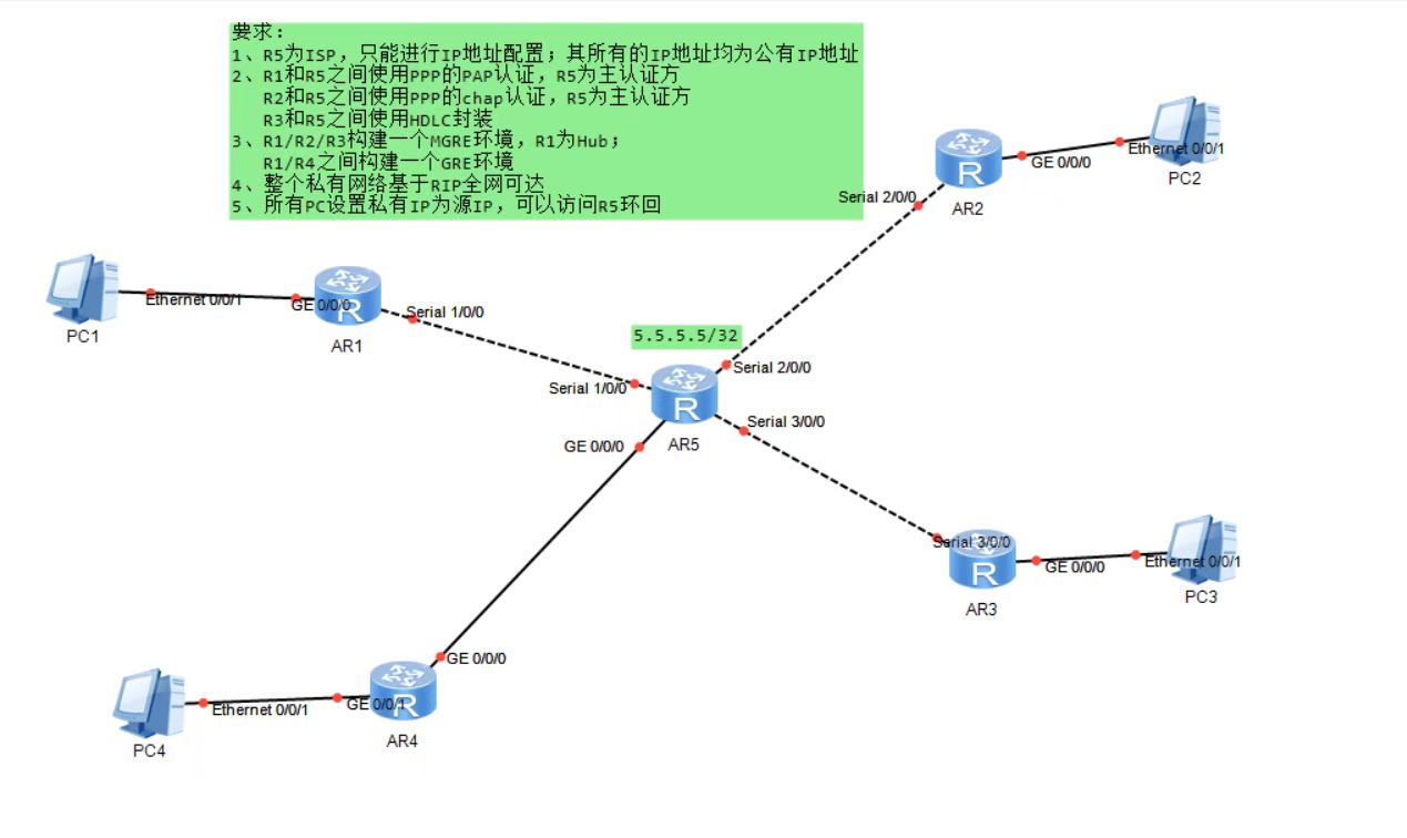
1,R5为ISP,,只能进行IP地址配置;其所有地址均配为公有IP地址
2,R1和R5间使用ppp的PAP认证,R5为主认证方;
R2和R5之间使用ppp的chap认证,R5为主认证方,
R3和R5之间使用HDLC封装。
3,R1/R2/R3构建一个MGRE环境,R1为Hub;R1/R4之间构建一个GRE环境。
4,整个私有网络基于RIP全网可达
5,所有PC设置私有IP为源IP,可以访问R5环回。
实验思路
1、首先根据拓扑结构合理分配IP地址,并对各个路由器的IP地址和R5环回接口的IP地址进行配置。
2、让私网中的边界路由器对ISP路由器做缺省路由。
3、根据实验要求,对需要配置不同类型认证的路由器进行认证配置,和需要不同封装的协议进行封装配置。
4、 根据实验要求,对R1、R2、R3构建一个MGRE环境,R1,R4间为点到点的GRE。
5、 对私网中的路由器进行RIP的配置。
实验操作
1.配置IP地址
r1
[r1]int s 1/0/0
[r1-Serial1/0/0]ip add 15.0.0.1 24
[r1-Serial1/0/0]int g 0/0/0
[r1-GigabitEthernet0/0/0]ip add 192.168.1.1 24

r2
[r2]int s 2/0/0
[r2-Serial2/0/0]ip add 25.0.0.1 24
[r2-Serial2/0/0]int g 0/0/1
[r2-GigabitEthernet0/0/0]ip add 192.168.2.1 24

r3
[r3]int s 3/0/0
[r3-Serial3/0/0]ip add 35.0.0.1 24
[r3-Serial3/0/0]int g 0/0/1
[r3-GigabitEthernet0/0/0]ip add 192.168.3.1 24

r4
[r4]int g0/0/0
[r4-GigabitEthernet0/0/0]ip add 45.0.0.1 24
[r4-GigabitEthernet0/0/0]int g0/0/1
[r4-GigabitEthernet0/0/1]ip add 192.168.4.1 24

r5(isp)
[isp]int s 1/0/0
[isp-Serial1/0/0]ip add 15.0.0.2 24
[isp-Serial1/0/0]int s 2/0/0
[isp-Serial2/0/0]ip add 25.0.0.2 24
[isp-Serial2/0/0]int s 3/0/0
[isp-Serial3/0/0]ip add 35.0.0.2 24
[isp-Serial3/0/0]int g 0/0/0
[isp-GigabitEthernet0/0/0]ip add 45.0.0.2 24
[isp-GigabitEthernet0/0/0]int l0
[isp-LoopBack0]ip add 5.5.5.5 24
2.写缺省路由
私网边界路由器配一条缺省指向isp
[r1]ip route-static 0.0.0.0 0 15.0.0.2
[r2]ip route-static 0.0.0.0 0 25.0.0.2
[r3]ip route-static 0.0.0.0 0 35.0.0.2
[r4]ip route-static 0.0.0.0 0 45.0.0.2
3.对需要配置不同类型认证的路由器进行认证配置,和需要不同封装的协议进行封装配置。
(1)R1和R5间使用ppp的PAP认证,R5为主认证方
我们把isp当做主认证方,ISP创建一个用户名和密码来提供r1进行ppp的pap认证
[isp]aaa
[isp-aaa]local-user haha password cipher 123456
[isp-aaa]local-user haha service-type ppp
[isp-aaa]q
[isp]int s 1/0/0
[isp-Serial1/0/0]ppp authentication-mode pap

[r1]int s 1/0/0
[r1-Serial1/0/0]ppp pap local-user haha password cipher 123456
(2)R2和R5之间使用ppp的chap认证,R5为主认证方
ISP创建一个用户名和密码来提供r2进行ppp的chap认证
[isp]aaa
[isp-aaa]local-user hehe password cipher 123456
[isp-aaa]local-user hehe service-type ppp
[isp-aaa]q
[isp]int s 2/0/0
[isp-Serial2/0/0]ppp authentication-mode chap

[r2]int s 2/0/0
[r2-Serial2/0/0]ppp chap user hehe
[r2-Serial2/0/0]ppp chap password cipher 123456
[r2-Serial2/0/0]q
(3)r3和r5之间使用HDLC封装更改串线协议,注意r3和r5都要更改,否则协议不一致,导致封装失败
[r3]int s 3/0/0
[r3-Serial3/0/0]link-protocol hdlc
Warning: The encapsulation protocol of the link will be changed. Continue? [Y/N]
:y
[isp]int s 3/0/0
[isp-Serial3/0/0]link-protocol hdlc
Warning: The encapsulation protocol of the link will be changed. Continue? [Y/N]
:y
4.配置GRE和MGRE环境
(1)R1/R2/R3构建一个MGRE环境,R1为Hub
r1创建虚拟接口
[r1]int t 0/0/0
[r1-Tunnel0/0/0]ip add 192.168.5.1 24

选择封装类型
[r1-Tunnel0/0/0]tunnel-protocol gre p2mp
[r1-Tunnel0/0/0]source 15.0.0.1

通过nhrp协议获取目标IP
[r1-Tunnel0/0/0]nhrp network-id 100
[r1-Tunnel0/0/0]nhrp entry multicast dynamic

r2分支站点
[r2]int t 0/0/0
[r2-Tunnel0/0/0]ip add 192.168.5.2 24
[r2-Tunnel0/0/0]tunnel-protocol gre p2mp

分支允许出接口发生变化
[r2-Tunnel0/0/0]source Serial 2/0/0

加入r1中心域
[r2-Tunnel0/0/0]nhrp network-id 100
[r2-Tunnel0/0/0]nhrp entry 192.168.5.1 15.0.0.1 register

r3重复r2配置
[r3]int t 0/0/0
[r3-Tunnel0/0/0]ip add 192.168.5.3 24
[r3-Tunnel0/0/0]tunnel-protocol gre p2mp
[r3-Tunnel0/0/0]source Serial 3/0/0
[r3-Tunnel0/0/0]nhrp network-id 100
[r3-Tunnel0/0/0]nhrp entry 192.168.5.1 15.0.0.1 register
(2)r1,r4做点到点的GRE
[r1]int t 0/0/1
[r1-Tunnel0/0/1]ip add 192.168.6.1 24
[r1-Tunnel0/0/1]tunnel-protocol gre
[r1-Tunnel0/0/1]source 15.0.0.1
[r1-Tunnel0/0/1]destination 45.0.0.1

[r4]int t 0/0/0
[r4-Tunnel0/0/0]ip add 192.168.6.2 24
[r4-Tunnel0/0/0]tunnel-protocol gre
[r4-Tunnel0/0/0]source 45.0.0.1
[r4-Tunnel0/0/0]destination 15.0.0.1
5.整个私有网络基于RIP全网可达
r1进行宣告
[r1]rip 1
[r1-rip-1]v 2
[r1-rip-1]network 192.168.1.0
[r1-rip-1]network 192.168.5.0
[r1-rip-1]network 192.168.6.0

r2进行宣告
[r2]rip 1
[r2-rip-1]v 2
[r2-rip-1]network 192.168.2.0
[r2-rip-1]network 192.168.5.0

r3进行宣告
[r3]rip 1
[r3-rip-1]v 2
[r3-rip-1]network 192.168.5.0
[r3-rip-1]network 192.168.3.0

r4进行宣告
[r4]rip 1
[r4-rip-1]v 2
[r4-rip-1]network 192.168.4.0
[r4-rip-1]network 192.168.6.0
6.所有PC设置私有IP为源IP,可以访问R5环回。
PC1IP地址:192.168.1.2/24    网关:192.168.1.1/24
PC2IP地址:192.168.2.2/24    网关:192.168.2.1/24
PC3IP地址:192.168.3.2/24    网关:192.168.3.1/24
PC4IP地址:192.168.4.2/24    网关:192.168.4.1/24

在边界设备做nat
r1
[r1]acl 2000
[r1-acl-basic-2000]rule permit source 192.168.1.0 0.0.0.255
[r1-acl-basic-2000]q
[r1]int s 1/0/0
[r1-Serial1/0/0]nat outbound 2000

r2
[r2]acl 2000
[r2-acl-basic-2000]rule permit source 192.168.2.0 0.0.0.255
[r2-acl-basic-2000]q
[r2]int s 2/0/0
[r2-Serial2/0/0]nat outbound 2000

r3
[r3]acl 2000
[r3-acl-basic-2000]rule permit source 192.168.3.0 0.0.0.255
[r3-acl-basic-2000]q
[r3]int s 3/0/0
[r3-Serial3/0/0]nat outbound 2000

r4
[r4]acl 2000
[r4-acl-basic-2000]rule permit source 192.168.4.0 0.0.0.255
[r4-acl-basic-2000]q
[r4]int g 0/0/0
[r4-GigabitEthernet0/0/0]nat outbound 2000

 浙公网安备 33010602011771号