
Untiy SRP 屏幕空间反射(SSR)
Untiy SRP 屏幕空间反射(SSR)
前段时间在Unity中使用SRP实现了屏幕空间反射,同时尝试使用Unity内置的RenderGraph来管理渲染管线,项目的主要框架是基于该教程Unity Custom SRP,记录一下实现的过程方便后面要使用的时候复习。
后处理准备
创建后处理设置及框架
由于SSR属于后处理的技术,因此在实现SSR之前还需要为后处理进行准备,URP中的后处理我已在这一篇文章Unity 体积云中介绍,而这次我准备使用SRP及RenderGraph进行框架的搭建。
首先便是后处理的属性设置,为了方便在Unity中编辑后处理相关属性,我使用ScriptableObject作为后处理设置的父类:
public abstract class PostEffectSetting : ScriptableObject, IComparable<PostEffectSetting>
 {
     public int m_Weight = 0;
     public bool m_Enable = true;

     public int CompareTo(PostEffectSetting other)
     {
         if (ReferenceEquals(this, other)) return 0;
         if (other is null) return 1;
         return m_Weight.CompareTo(other.m_Weight);
     }

    public abstract void Record(
         RenderGraph renderGraph,
         CullingResults cullingResults,
         Camera camera,
         in CameraRendererTextures cameraTextures,
         TextureHandle target);
}
其中m_Enable和m_Weight这两个参数为所有后处理都有的属性,前者为是否开启该后处理,后者为该后处理的权重,由于不同后处理之间执行的顺序不同最后输出的结果也不同,因此需要根据权重进行排序。
接下来就是使用一个类统一管理所有的后处理效果,由于需要在Unity中编辑需要的后处理,因此需要添加[Serializable] ,并提供一个开关所有后处理的开关,在Record中排序所有后处理并调用:
[Serializable]
public class PostEffectManager
{
    private static readonly ProfilingSampler sm_Sampler = new ProfilingSampler("PostEffect");

    [FormerlySerializedAs("m_PostEffects")] [SerializeField] private List<PostEffectSetting> m_PostEffectSettings = new();
    [SerializeField] private bool m_Enabled = true;

    public bool IsActive => m_PostEffectSettings != null && m_PostEffectSettings.Count > 0 && m_Enabled;


    /// <summary>
    /// 执行屏幕后处理
    /// </summary>
    public void Record(
        RenderGraph renderGraph,
        CullingResults cullingResults,
        Camera camera,
        ScriptableRenderContext renderContext,
        in CameraRendererTextures cameraTextures)
    {
        if(!IsActive) return;
        using var groupSampler = new RenderGraphProfilingScope(renderGraph, sm_Sampler);

        m_PostEffectSettings.Sort(); // 根据后处理的权重进行排序

        for(int i = 0; i < m_PostEffectSettings.Count; i++)
        {
            if(m_PostEffectSettings[i] == null || !m_PostEffectSettings[i].m_Enable) continue;

            m_PostEffectSettings[i].Record(
                renderGraph,
                cullingResults,
                camera,
                cameraTextures,
                cameraTextures.m_ColorTexture);
        }

    }
}
最后在继承了RenderPipelineAsset的类中添加一个成员变量PostEffectManager即可,此时便可在Unity中自定义添加后处理。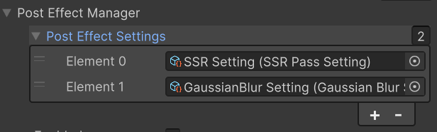
随后创建一个类继承PostEffectSetting来存储SSR中可调节的参数:
[CreateAssetMenu(menuName = "Rendering/Custom PostEffect/SSR")]
public class SSRPassSetting : PostEffectSetting
{
	...

    public override void Record(
         RenderGraph renderGraph,
         CullingResults cullingResults,
         Camera camera,
         in CameraRendererTextures cameraTextures,
         TextureHandle target)
    {
        SSRPass.Record(
            renderGraph,
            cullingResults,
            camera,
            cameraTextures,
            target,
            this);
    }
}
这里将实际的渲染逻辑委托给了另一个类SSRPass,具体的实现在该类中实现,该类的主要函数如下:
public class SSRPass
{
    private static ProfilingSampler sm_Sampler = new ProfilingSampler("SSR");

    private Material m_Material;

    public Material SSRMaterial{
        get{
            if (m_Material == null) {
                m_Material = CoreUtils.CreateEngineMaterial(Shader.Find("DSM RP/SSR"));
            }
            return m_Material;
        }

    }


    private TextureHandle m_SrcTexture, m_DstTexture,
        m_DepthTexture, m_NormalTexture;

    private RendererListHandle m_RenderList;

    private int m_CameraWidth, m_CameraHeight;

    private SSRPassSetting m_Setting = null;

    public void Render(RenderGraphContext context)
    {
		if(m_Setting == null) return;

        CommandBuffer cmd = context.cmd;

        SSRMaterial.SetTexture(CameraRendererTextures.m_CameraColorTextureId, m_SrcTexture);
        SSRMaterial.SetTexture(CameraRendererTextures.m_CameraDepthTextureId, m_DepthTexture);
        SSRMaterial.SetTexture(CameraRendererTextures.m_NormalTextureId, m_NormalTexture);

        cmd.SetRenderTarget(m_DstTexture, RenderBufferLoadAction.DontCare, RenderBufferStoreAction.Store);

        cmd.DrawProcedural(Matrix4x4.identity, SSRMaterial, 0, MeshTopology.Triangles, 3);

        context.renderContext.ExecuteCommandBuffer(cmd);
        cmd.Clear();
    }

    public static void Record(
        RenderGraph renderGraph,
        CullingResults cullingResults,
        Camera camera,
        in CameraRendererTextures cameraTextures,
        TextureHandle target,
        SSRPassSetting setting)
    {
		using RenderGraphBuilder ssrBuilder = renderGraph.AddRenderPass(
                sm_Sampler.name, out SSRPass pass, sm_Sampler);

        int width = camera.pixelWidth, height = camera.pixelHeight;

        pass.m_Setting = setting;
        pass.m_CameraWidth = width;
        pass.m_CameraHeight = height;

        // 使用颜色及深度图
        pass.m_SrcTexture = ssrBuilder.ReadWriteTexture(target);
        pass.m_DepthTexture = ssrBuilder.ReadTexture(cameraTextures.m_DepthTexture);
        pass.m_NormalTexture = ssrBuilder.ReadTexture(cameraTextures.m_NormalTexture);

        // 遮罩纹理
        TextureDesc texDesc = new TextureDesc(width, height)
        {
            name = "MaskTexture",
            format = GraphicsFormat.R8_SNorm,
        };
        pass.m_MaskTexture = ssrBuilder.ReadWriteTexture(renderGraph.CreateTexture(texDesc));

        // 临时纹理
        texDesc.format = SystemInfo.GetGraphicsFormat(DefaultFormat.HDR);
        texDesc.name = "TmpTexture";
        pass.m_DstTexture = ssrBuilder.WriteTexture(renderGraph.CreateTexture(texDesc));

        // 打包好的Hiz纹理
        texDesc.format = GraphicsFormat.R32_SFloat;
        texDesc.name = "Package Hiz Texture";
        texDesc.useMipMap = true;
        texDesc.autoGenerateMips = false;   // 不能自动生成MipMap,否则拷贝的会被覆盖
        pass.m_PackageHizTexture = ssrBuilder.ReadWriteTexture(renderGraph.CreateTexture(texDesc));

        // Hiz纹理
        pass.m_HizTextures = new TextureHandle[setting.m_HizCount];
        texDesc.useMipMap = false;
        for (int i = 0, hizWidth = width / 2, hizHeight = height / 2;
            i < pass.m_HizTextures.Length; i++, hizWidth /= 2, hizHeight /= 2)
        {
            texDesc.width = hizWidth;
            texDesc.height = hizHeight;
            texDesc.enableRandomWrite = true;
            texDesc.name = "HizTexture" + i;
            pass.m_HizTextures[i] = ssrBuilder.ReadWriteTexture(
                renderGraph.CreateTexture(texDesc));
        }

        pass.m_RenderList = ssrBuilder.UseRendererList(renderGraph.CreateRendererList(
            new RendererListDesc(SSRPass.m_ShaderTagID, cullingResults, camera)
            {
                renderQueueRange = RenderQueueRange.all,
                renderingLayerMask = setting.m_RenderingLayerMask,
                overrideMaterial = SSRPass.m_SSRLitMaterial,
                overrideMaterialPassIndex = 1
            }));

        ssrBuilder.SetRenderFunc<SSRPass>(
            static (pass, context) => pass.Render(context));
    }
在Record函数中,我们需要对需要使用的纹理进行创建或标记,并将准备好的纹理传递给调用RenderGraph的AddRenderPass输出的数据pass中。在Render中执行实际的渲染流程。
使用全屏三角形覆盖屏幕
由于后处理需要对渲染管线输出的纹理进行处理,因此需要创建一个覆盖整个纹理的三角形来渲染。相比使用四边形进行渲染,使用覆盖全屏的三角形进行渲染效率更高,原因如下:
- 四边形在渲染时会被拆为两个三角形渲染,但是由于GPU执行光栅化的时候是以Tile为单位进行渲染的,也就是多个像素组成的像素块,因此在两个三角形的衔接处的像素会被渲染多次,造成Overdraw。
- 相比四边形,使用三角形的缓存命中率更高。
- 现代GPU在光栅化之前会使用保护带裁剪(Guard Band Clipping)来进行裁剪,因此全屏三角形超出屏幕的部分不会被裁剪掉,也不会造成额外的开销。
在顶点着色器中创建三角形的代码如下:
struct Varyings
{
    float4 posCS : SV_POSITION;
    float2 uv : TEXCOORD0;
};

/*
 *  1
 *  |\
 *  | \
 *  |  \
 *  |___ \
 *  0       2
 */
// 覆盖全屏的三角形
Varyings DefaultPostEffectVertex(uint vertexID : SV_VertexID)
{
    Varyings output;

    float2 uv = float2((vertexID << 1) & 2, vertexID & 2);
    output.uv = uv;
    output.posCS = float4(output.uv * 2.0 - 1.0, 0, 1.0);

    [flatten]
    if (_ProjectionParams.x < 0) {
        output.uv.y = 1 - output.uv.y;
    }

    return output;
}

Shader "DSM RP/SSR"
{
    SubShader
    {
        Cull Off
        ZTest Always
        ZWrite Off

        HLSLINCLUDE
        #include "../../../ShaderLibrary/Common.hlsl"
        #include "../PostEffectCommon.hlsl"
        #include "SSRPass.hlsl"
        ENDHLSL


        Pass
        {
            Name "SSR"
            Tags {"LightMode" = "DSMLit"}

            HLSLPROGRAM
            #pragma vertex DefaultPostEffectVertex
            #pragma fragment SSRPassFragment
            #pragma target 5.0
            ENDHLSL
        }
    }
}
其中_ProjectionParams为Unity内置的投影矩阵的信息,x值表示该平台下的矩阵是否为翻转矩阵,需要判断该值的正负来消除平台差异。在SSRPassFragment中将实现具体的算法,此时先输出一下uv来看看全屏三角形是否创建成功。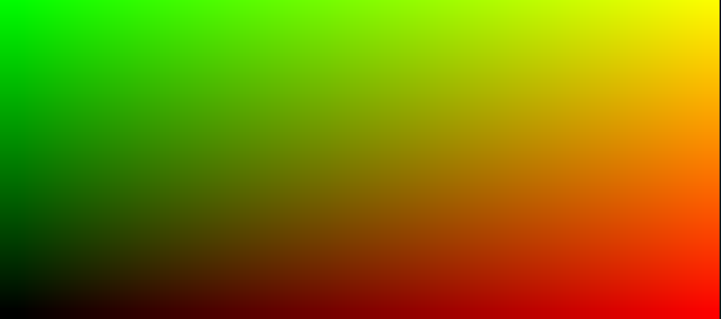
至此实现SSR的准备也算完成了,至于在SRP中法线纹理如何获取,我是先渲染物体的时候额外设置了一个RT:
RenderTargetIdentifier[] renderTargets = {
    m_ColorTexture, m_NormalTexture
};

cmd.SetRenderTarget(renderTargets, m_DepthTexture);
并在光照Pass中将法线输出到该RT中:
float4 LitPassFragment(Varyings i, out float3 normal : SV_TARGET1) : SV_TARGET0
{
	...

    normal = EncodeNormal(surface.normal);
}
SSR原理
屏幕空间反射其实也是屏幕空间光线追踪,其原理也十分简单,大致可以分为以下三个步骤:
- 在当前像素使用深度、法线等信息构建射线。
- 沿着构建的射线步进,并判断射线是否与步进处的物体相交,通常使用深度来判断。
- 若射线与物体相交则对相交处的像素及当前像素进行处里。
从对一二步采取不同的方法,该算法视图空间SSR及屏幕空间SSR。两者的区别为前者构建的是视图空间的射线,并在视图空间中步进;后者构建的是屏幕空间的2D射线并在2D空间步进,也就是纹理上画线,因此步进算法通常使用DDA算法。接下来便分别阐述两种方法的基本实现及优化。
视图空间SSR
构建射线
根据上面的三个步骤,首先需要构建视图空间的坐标,回顾一下一个顶点变换到屏幕的流程,分别经过了:局部空间——世界空间——视图空间——齐次裁剪空间——标准化设备(NDC)空间——屏幕空间。因此需要先获取NDC空间下坐标,该坐标可以通过将纹理坐标映射到[-1, 1]和当前像素的深度来获得。由于我们没有顶点变换时齐次裁剪操作的信息,因此只能通过将w设为1并最后除以w来处理,具体实现如下:
float GetCameraDepth(float2 uv)
{
    return SAMPLE_DEPTH_TEXTURE(_CameraDepthTexture, sampler_point_clamp, uv);
}

float3 GetViewPosition(float2 uv)
{
    float4 posCS = float4(uv * 2 - 1, GetCameraDepth(uv), 1);
    #if UNITY_UV_STARTS_AT_TOP
    posCS.y *= -1;
    #endif

    float4 posVS = mul(Inverse(UNITY_MATRIX_P), posCS);
    posVS /= posVS.w;

    return posVS.xyz;
}
由于不同图形API的纹理坐标标准不同,因此还需要通过Unity内置的宏UNITY_UV_STARTS_AT_TOP来消除平台差异,由于视图空间下相机是原点,因此得到视图坐标后也得到了视线方向,输出一下视线方向看看正不正确。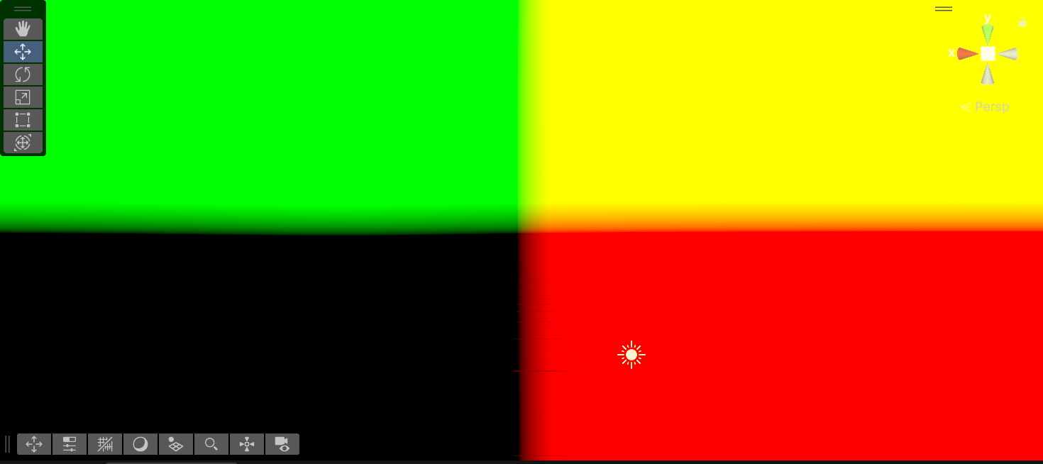
此时便可以从法线纹理中获取法线并将其变换到视图空间,SSR需要追踪的射线为反射光线,因此还需要通过法线和视线方向计算反射光线:
float4 SSRPassFragment(Varyings input) : SV_TARGET
{
    float4 reflectCol = float4(0, 0, 0, 1);

    // 获取RayMarching所需的信息
    float3 normal = SAMPLE_TEXTURE2D(_NormalTexture, sampler_NormalTexture, input.uv).xyz;
    [branch]
    if (all(normal == 0)) return reflectCol;    // 排除天空盒
    normal = DecodeNormal(normal);
    normal = normalize(mul((float3x3)unity_MatrixV, normal));
    float3 posVS = GetViewPosition(input.uv);
    float3 viewDir = normalize(posVS);
    float3 rayDir = normalize(reflect(viewDir, normal));

    Ray ray;
    ray.rayDir = rayDir;
    ray.origin = posVS;

    reflectCol = ViewSpaceSSR(ray);

    return reflectCol;
}
自此射线就构造完毕了,接下来就是在ViewSpaceSSR中追踪光线。
RayMarching
又到了经典的RayMarching环节,该步骤设定一个步频并不断步进反射光线即可,在每次步进的时候还需要判断射线与当前位置的物体是否相交:
float4 RayMarching(Ray ray, float marchCount, float marchStep, out float4 outCol, out float3 endPos)
{
    float3 currPos = ray.origin;
    outCol = float4(0, 0, 0, 1);

    [loop]
    for (int i = 0; i < marchCount; ++i) {
        endPos = currPos;
        currPos += ray.rayDir * marchStep;

        float depthDis;
        // 当 depthDis > 0 时可以直接结束
        CheckCurrPos(currPos, outCol, depthDis);
        if (depthDis > 0) return outCol;
    }
    return outCol;
}
其中CheckCurrPos便是进行相交检测,进行检测需要还原当前位置对应的像素的uv,将当前位置乘上投影矩阵并手动进行齐次除法,随后映射到[0, 1]即可获得uv,通过uv来获取对应的深度并与当前的深度进行比较:
bool GetCurrDepthAndUV(float3 currPos, out float currDepth, out float2 uv)
{
    // 变换到NDC空间
    float4 posCS = mul(UNITY_MATRIX_P, float4(currPos, 1));
    currDepth = posCS.w; // 根据投影矩阵可以得到齐次裁剪空间下的 w 就是视图空间下的深度
    posCS.xyz /= posCS.w;

    // _ProjectionParams 为 1 或 -1
    // 重建 uv 来获取采样点的深度及颜色
    uv = float2(posCS.x, posCS.y * _ProjectionParams.x) * 0.5 + 0.5;

    return (0 <= uv.x && uv.x <= 1 && 0 <= uv.y && uv.y <= 1);
}

/*
 * return:
 *  true: 在当前位置获取了颜色信息
 *  false: 为获取颜色信息
 */
bool CheckCurrPos(float3 currPos, out float4 outCol, out float depthDis)
{
    outCol = float4(0, 0, 0, 1);
    // 获取当前位置的深度
    float currDepth;
    float2 uv;
    [branch]
    if (!GetCurrDepthAndUV(currPos, currDepth, uv)) {
        depthDis = 1;
        return false;
    }

    float depthTex = GetCameraLinearDepth(uv);
    depthDis = currDepth - depthTex;
    // 射线已经穿过了物体
    [branch]
    if (depthDis > 0) {
        bool inRange = depthDis <  _HitThreshold;  // 在阈值范围内
        outCol = inRange ? GetCameraColor(uv) : outCol;
        return inRange;
    }
    return false;
}
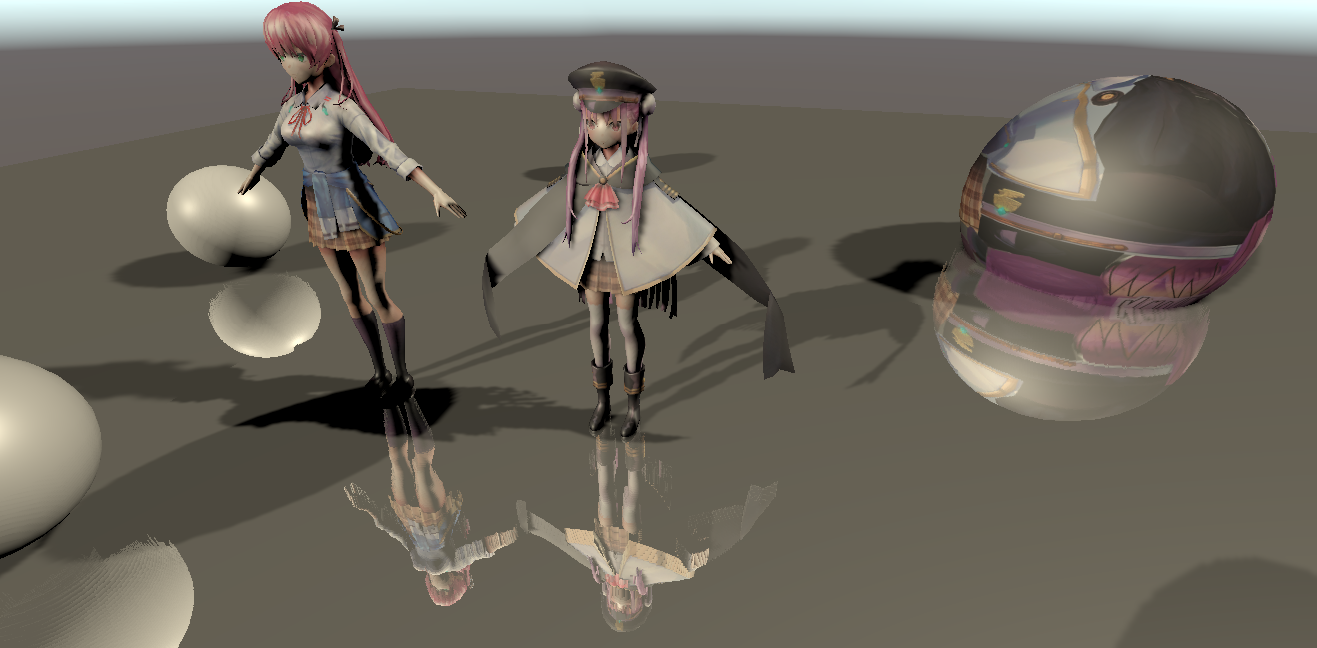
直接将返回的颜色叠加到源颜色上,此时便完成了一个最基本的SSR了。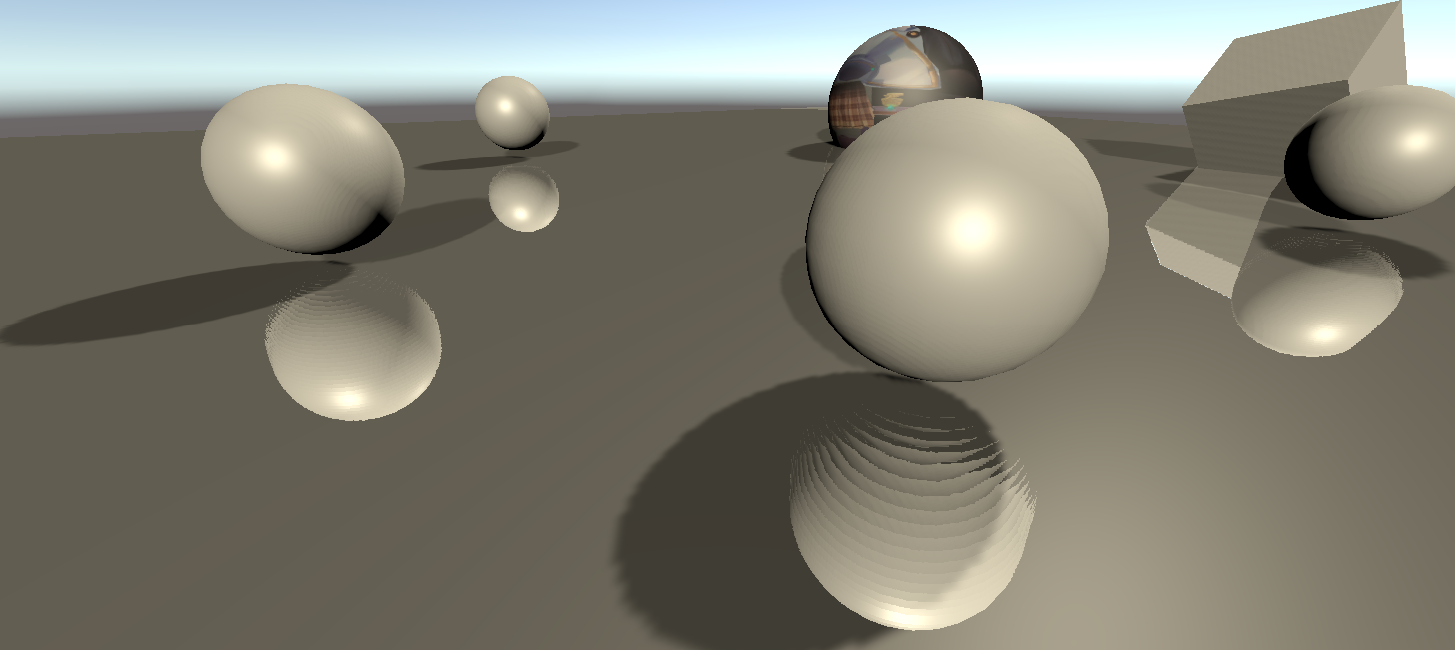
从这张图可以看出屏幕空间反射的缺陷,由于最右边球的右端在屏幕之外,因此当地板反射的光线到达理应相交的位置时无法获得信息,导致反射的缺失,这是屏幕空间算法无法避免的缺陷。解决这个问题的一种方法是在相机处朝六个方向都进行渲染,当光线步进超出一个纹理的范围时便去其他纹理查找,但这方法开销很大因此我没见过有谁实现出来。
另一个很明显的问题是在离屏幕很近的的位置反射出来的球体有明显的分层现象,这里我选择的Ray Marching的步频为0.1,如此高的采样频率依然产生了明显分层,因此这个问题很难忽视。造成这个问题的原因是顶点经过投影变换后在不同深度的分布是不均匀的,因此同样长度的射线在近平面对应的像素量要远大于在远平面对应的像素量。
可参考这个图片,在屏幕平面,也就是近平面中ac与cb的长度相同,对应的像素相同,但是沿着视线方向两条直线对应的直线AC和CB并不是等长的。这就会导致当射线步进到的位置与相机的距离较近时,每次步进会略过更多的像素,造成欠采样影响质量;当步进到的位置与相机较远时,相邻的多次步进会采样到同一像素,造成过采样影响效率。而屏幕空间SSR的出现正是为了解决这些问题。
但在在视图空间下也是有补救的方法的,那便是使用二分查找法,具体实现也比较简单,当检测射线与物体相交的时候判断深度的差是否在阈值范围内,若不在阈值范围内则回退并减半步进距离:
// 二分查找,来准确定位反射光线打中的像素
float4 BinarySearch(Ray ray)
{
    static const int MaxBinarySearchCount = 5;   // 限制查找次数

    float step = _RayMarchingStep * 0.5;
    float3 currPos = ray.origin;
    float4 outCol = float4(0, 0, 0, 1);

    [unroll]
    for (int i = 0; i < MaxBinarySearchCount; i++) {
        float3 prePos = currPos;
        currPos += ray.rayDir * step;

        float depthDis;
        if (CheckCurrPos(currPos, outCol, depthDis)) break;
        [flatten]
        if (depthDis > 0) { // 回退
            currPos = prePos;
            step *= 0.5;
        }
    }
    return outCol;
}
需要注意的是需要考虑在二分起点与终点之间没有满足阈值深度的位置,当遇到这种情况会使二分无法停止,因此需要限制二分的次数,这里限制为5次。添加二分查找后的结果虽然还是不尽人意但相比上面的严重分层还是好了很多的,且步频越大效果越明显。
结果输出
原纹理与反射纹理的叠加我只用了混合叠加,单独添加了一个Blend Pass才混合两张纹理,具体实现如下:
Shader "DSM RP/Blend"
{
    Properties
    {
        [Enum(UnityEngine.Rendering.BlendMode)] _SrcBlend("Src Blend", Float) = 1
        [Enum(UnityEngine.Rendering.BlendMode)] _DstBlend("Dst Blend", Float) = 0
        [Enum(UnityEngine.Rendering.BlendOp)] _BlendOp("Blend Operation", Float) = 0
    }
    SubShader
    {
        Cull Off
        ZTest Always
        ZWrite Off

        HLSLINCLUDE
        #include "../ShaderLibrary/Common.hlsl"
        #include "PostEffect/PostEffectCommon.hlsl"
        #include "BlendPass.hlsl"
        ENDHLSL


        Pass
        {
            Name "Blend"
            Tags {"LightMode" = "DSMLit"}
            Blend [_SrcBlend] [_DstBlend]
            BlendOp [_BlendOp]

            HLSLPROGRAM
            #pragma vertex DefaultPostEffectVertex
            #pragma fragment BlendPassFragment
            #pragma target 5.0
            ENDHLSL
        }
    }
}


#ifndef __BLENDPASS_HLSL__
#define __BLENDPASS_HLSL__

TEXTURE2D(_SrcTexture);

float4 BlendPassFragment(Varyings i) :SV_Target
{
    return SAMPLE_TEXTURE2D(_SrcTexture, sampler_linear_clamp, i.uv);
}


#endif
为了方便后续对混合的使用,我创建了一个类来单独管理混合操作:
public readonly ref struct BlendSetting
{
    public readonly TextureHandle
        m_SrcTexture, m_DstTexture;
    public readonly BlendMode m_SrcBlend;
    public readonly BlendMode m_DstBlend;
    public readonly BlendOp m_BlendOp;
    public BlendSetting(
        TextureHandle srcTex,
        TextureHandle dstTex,
        BlendMode srcBlend = BlendMode.SrcAlpha,
        BlendMode dstBlend = BlendMode.OneMinusSrcAlpha,
        BlendOp blendOp = BlendOp.Add)
    {
        m_SrcBlend = srcBlend;
        m_DstBlend = dstBlend;
        m_BlendOp = blendOp;
        m_SrcTexture = srcTex;
        m_DstTexture = dstTex;
    }
}

public class BlendPass
{
    private static readonly ProfilingSampler sm_Sampler = new ProfilingSampler("Blend");

    private BlendMode m_SrcBlend;
    private BlendMode m_DstBlend;
    private BlendOp m_BlendOp;

    private TextureHandle m_SrcTexture;
    private TextureHandle m_DstTexture;

    static private Material sm_Material;

    private static readonly string sm_BlendShaderName = "DSM RP/Blend";

    public static readonly int
        m_SrcBlendId = Shader.PropertyToID("_SrcBlend"),
        m_DstBlendId = Shader.PropertyToID("_DstBlend"),
        m_BlendOpId = Shader.PropertyToID("_BlendOp"),
        m_SrcTextureId = Shader.PropertyToID("_SrcTexture");

    private void Render(RenderGraphContext context)
    {
        sm_Material = sm_Material == null ?
            CoreUtils.CreateEngineMaterial(sm_BlendShaderName) : sm_Material;

        CommandBuffer cmd = context.cmd;
        sm_Material.SetFloat(m_SrcBlendId, (float)m_SrcBlend);
        sm_Material.SetFloat(m_DstBlendId, (float)m_DstBlend);
        sm_Material.SetFloat(m_BlendOpId, (float)m_BlendOp);
        sm_Material.SetTexture(m_SrcTextureId, m_SrcTexture);

        cmd.SetRenderTarget(m_DstTexture);

        cmd.DrawProcedural(Matrix4x4.identity, sm_Material, 0, MeshTopology.Triangles, 3);

        context.renderContext.ExecuteCommandBuffer(cmd);
        cmd.Clear();
    }

    public static void Record(RenderGraph renderGraph, BlendSetting setting)
    {
        using RenderGraphBuilder builder = renderGraph.AddRenderPass(
            sm_Sampler.name, out BlendPass pass, sm_Sampler);

        pass.m_SrcBlend = setting.m_SrcBlend;
        pass.m_DstBlend = setting.m_DstBlend;
        pass.m_BlendOp = setting.m_BlendOp;
        pass.m_SrcTexture = builder.ReadTexture(setting.m_SrcTexture);
        pass.m_DstTexture = builder.WriteTexture(setting.m_DstTexture);

        builder.SetRenderFunc<BlendPass>(
            static (pass, context) => pass.Render(context));
    }
}
封装了混合操作后只需要在SSRPass中的Record函数中调用即可:
[CreateAssetMenu(menuName = "Rendering/Custom PostEffect/SSR")]
public class SSRPassSetting : PostEffectSetting
{
	...

    [Header("SSR Settings")]
    [Range(0, 1)] public float m_BlendFactor = 1;
    public BlendMode m_SrcBlend = BlendMode.SrcAlpha;
    public BlendMode m_SSRBlend = BlendMode.One;
    public BlendOp m_BlendOp = BlendOp.Add;
}

public static void Record(...)
{
    ...

    BlendSetting blendSetting = new BlendSetting(
        pass.m_DstTexture, pass.m_SrcTexture,
        setting.m_SSRBlend, setting.m_SrcBlend, setting.m_BlendOp);
    BlendPass.Record(renderGraph, blendSetting);
}
最后得到的结果如下:
屏幕空间SSR
屏幕空间的屏幕空间反射,这名字起来有点奇怪。由于上面提到的欠采样、过采样等视图空间下的缺点,屏幕空间的SSR便应运而生,相比视图空间,屏幕空间在构建反射光线后还将光线投影到屏幕空间,在Ray Marching是使用画线算法进行步进,如此每次步进的步长都是均匀的,在避免过采样的无效损耗的同时还提高的渲染的质量。
构建光线
首先第一步便是构建光线,前面相同的部分就先跳过,如前面所说,在获取视图空间的光线后,还需要将其变换到屏幕空间,而在屏幕这个二维空间,两点确认一条直线,因此只需要将起点和重点变换即可:
[branch]
if (_RayMarchingStep <= 0 || _RayMarchingMaxDistance <= 0) return float4(0, 0, 0, 1);

// 限制到近平面内
const float nearPlaneZ = -0.001;
float rayLen = (ray.origin.z + ray.rayDir.z * _RayMarchingMaxDistance) >= nearPlaneZ ?
(nearPlaneZ - ray.origin.z) / ray.rayDir.z : _RayMarchingMaxDistance;
float3 endPosVS = ray.origin + ray.rayDir * rayLen;

// 转换到NDC空间 [-1, 1]
float4 startCS = mul(UNITY_MATRIX_P, float4(ray.origin, 1));
float4 endCS = mul(UNITY_MATRIX_P, float4(endPosVS, 1));
const float startK = 1.0 / startCS.w, endK = 1.0 / endCS.w;
startCS *= startK;
endCS *= endK;

endCS += (DistanceSquared(startCS, endCS) < 0.0001f) ? float4(0.01, 0.01, 0, 0) : 0;

// 变换到屏幕空间
const float2 WH = float2(GetCameraTexWidth(), GetCameraTexHeight());
float2 startSS = float2(startCS.x, startCS.y)  * 0.5 + 0.5;
float2 endSS = float2(endCS.x, endCS.y)  * 0.5 + 0.5;
startSS *= WH;
endSS *= WH;
由于后续要需要比较像素与光线之间的深度,因此需要还原视图空间下的深度,若是直接使用视图空间下的深度并进行迭代比较,会产生错误的结果,原因正是上面提到的顶点经过投影变换后在相邻像素之间的深度分布是不均匀的。虽然可以通过乘上投影矩阵的逆来还原深度,但若是每次比较都变换性能消耗又很高。所幸在屏幕空间下 1 / View.w 是线性变化的,因此可以通过视图空间下的 w 分量来还原出深度。
DDA画线算法
由于是沿着一个二维直线进行步进,因此使用画线算法是最合适的,而相比Bresenham画线算法,DDA算法的浮点数运算更多,更适合GPU计算,因此这里使用DDA算法进行步进。数值微分算法(Digital Differential Analyzer)是一种基于差分的算法,该算法的基本思想是根据直线的斜率决定步进的方向,并沿着步进方向迭代一个单位,同时通过斜率递增另一个方向。当直线的斜率小于1的时候需要沿着x方向进行迭代,否则沿着y方向进行迭代,否则就会出现离散的点。大致的算法如下:
void DDA(int2 start, int2 end) {
    float2 offset = end - start;
    bool steep = abs(offset.y) > abs(offset.x);
    if (steep) {  // 若斜率大于1则互换
        offset = offsetSS.yx;
        offset = startSS.yx;
        end = end.yx;
    }
    float stepDir = sign(offset.x), invDx = stepDir / offset.x;
    offset = float2(stepDir, offset.y * invDx);

    int2 curr = start;
	for (int i = start.x * stepDir; i <= end.x * stepDir; i++) {
		draw(curr);
		curr += offset;
}
可见这个算法还是十分简单的,在上面的框架上添加深度的计算和比较,即可实现屏幕空间下的SSR,完整的代码如下:
float4 SSR2DRayMarching(
    float2 currPosSS, float2 endPosSS, float2 offsetSS,
    float3 currPosVS, float3 offsetVS,
    float currK, float offsetK,
    float stepDir, bool steep)
{
    const int marchingCount = _RayMarchingMaxDistance / _RayMarchingStep;
    float2 invWH = 1.f / float2(GetCameraTexWidth(), GetCameraTexHeight());
    float preZ = currPosVS.z / currK;

    [loop]
    for (int iii = 0; (currPosSS.x * stepDir < endPosSS.x * stepDir) && iii < marchingCount; ++iii)
    {
        currPosSS += offsetSS, currPosVS.z += offsetVS.z, currK += offsetK;

        float2 uv = steep ? currPosSS.yx : currPosSS.xy;
        uv *= invWH;
#if UNITY_UV_STARTS_AT_TOP
        uv.y = 1 - uv.y;    // 需要进行反转
#endif
        float sceneZ = -GetCameraLinearDepth(uv);

        float minZ = preZ;
        // 通过 K 获得当前位置的深度
        //float maxZ = (currPosVS.z + 0.5f * offsetVS.z) / (currK + 0.5f * offsetK);
        float maxZ = currPosVS.z / currK;
        preZ = maxZ;
        [flatten]
        if (minZ > maxZ){
            SwapFloat(minZ, maxZ);
        }
        bool inRange = all(0 <= uv && uv <= 1);
        [branch]
        if(!inRange) break;

        bool hit = minZ <= sceneZ && maxZ >= sceneZ - _HitThreshold;
        [branch]
        if (hit) {
            return GetCameraColor(uv);
        }
    }

    return float4(0, 0, 0, 1);
}

// 屏幕空间的 RayMarching,输入为视图空间的反射光线
float4 ScreenSpaceSRR(Ray ray)
{
    [branch]
    if (_RayMarchingStep <= 0 || _RayMarchingMaxDistance <= 0) return float4(0, 0, 0, 1);

    // 限制到近平面内
    const float nearPlaneZ = -0.001;
    float rayLen = (ray.origin.z + ray.rayDir.z * _RayMarchingMaxDistance) >= nearPlaneZ ?
        (nearPlaneZ - ray.origin.z) / ray.rayDir.z : _RayMarchingMaxDistance;
    float3 endPosVS = ray.origin + ray.rayDir * rayLen;

    // 转换到NDC空间 [-1, 1]
    float4 startCS = mul(UNITY_MATRIX_P, float4(ray.origin, 1));
    float4 endCS = mul(UNITY_MATRIX_P, float4(endPosVS, 1));
    const float startK = 1.0 / startCS.w, endK = 1.0 / endCS.w;
    startCS *= startK;
    endCS *= endK;

    endCS += (DistanceSquared(startCS, endCS) < 0.0001f) ? float4(0.01, 0.01, 0, 0) : 0;

    // 变换到屏幕空间
    const float2 WH = float2(GetCameraTexWidth(), GetCameraTexHeight());
    float2 startSS = float2(startCS.x, startCS.y)  * 0.5 + 0.5;
    float2 endSS = float2(endCS.x, endCS.y)  * 0.5 + 0.5;
    startSS *= WH;
    endSS *= WH;

    // 由于后续需要得知当前点的深度,因此还需要保存视图空间下的坐标
    // 由于屏幕空间的步进和视图空间的步进不是线性关系,因此需要使用齐次坐标下的 W 来进行联系
    float3 startQ = ray.origin * startK;
    float3 endQ = endPosVS * endK;

    float2 offsetSS = endSS - startSS;
    bool steep = abs(offsetSS.y) > abs(offsetSS.x); // 斜率是否大于1
    [flatten]
    if (steep) {  // 若斜率大于1则互换
        offsetSS = offsetSS.yx;
        startSS = startSS.yx;
        endSS = endSS.yx;
    }

    // 步进的方向                       转换为正
    float stepDir = sign(offsetSS.x), invDx = stepDir / offsetSS.x;
    // 每次步进各个变量的偏移
    float3 offsetQ = (endQ - startQ) * invDx;
    float offsetK = (endK - startK) * invDx;
    offsetSS = float2(stepDir, offsetSS.y * invDx);

    offsetSS *= _HizStride, offsetQ *= _HizStride, offsetK *= _HizStride;

    float2 currSS = startSS;
    float3 currQ = startQ;
    float currK = startK;

    float4 reflectCol;
#if defined(SCREENSPACEHIEZ)
    reflectCol = SSR2DRayMarchingWithHiz(currSS, endSS, offsetSS, currQ, offsetQ, currK, offsetK, stepDir, steep);
#elif defined(SCREENSPACE)
    reflectCol = SSR2DRayMarching(currSS, endSS, offsetSS, currQ, offsetQ, currK, offsetK, stepDir, steep);
#endif

    return reflectCol;
}
Hierarchical-Z
SSR的关键是查找反射管线的相交点,同时涉及了深度的比较,而想要优化该算法,就需要加速相交点的查找,也就是尽量减少深度的比较,而引入Hi-Z的巧妙之处就是将深度进行分层存储,通过使用更粗粒度的深度来加速步进。引入该结构使SSR在步进之前又多了一步,也就是Hierarchical-Z的生成,同时在比较深度时也改变了步进策略。
Hierarchical-Z Buffer的生成
Hi-Z的生成与Mipmap十分相似,唯一的区别就是Mipmap是一个像素对应四个像素的平均值,而Hi-Z则是取最大值或最小值,在该场景下需要取的是最大值,在这里我是用ComputeShader进行Hi-Z的生成:
#pragma kernel GenerateSSRHieZ

Texture2D<float> _DepthTexture;
SamplerState sampler_DepthTexture;

RWTexture2D<float4> _HizTexture;

float SampleDepth(float2 uv, float2 offset)
{
    return _DepthTexture.SampleLevel(sampler_DepthTexture, uv, 0, offset);
}

[numthreads(1,1,1)]
void GenerateSSRHieZ (uint3 id : SV_DispatchThreadID)
{
    // 计算当前像素需要采样的四个纹理坐标并采样
    float width, height;
    _HizTexture.GetDimensions(width, height);
    float2 uv = float2(id.xy) / float2(width, height);
    float depth0 = SampleDepth(uv, float2(-0.5, -0.5));
    float depth1 = SampleDepth(uv, float2(0.5, -0.5));
    float depth2 = SampleDepth(uv, float2(0.5, 0.5));
    float depth3 = SampleDepth(uv, float2(-0.5, 0.5));

    // 求四个深度的最大值
    float maxDepth = max(max(depth0, depth1), max(depth2, depth3));

    // 写入输出纹理
    _HizTexture[id.xy] = maxDepth;
}
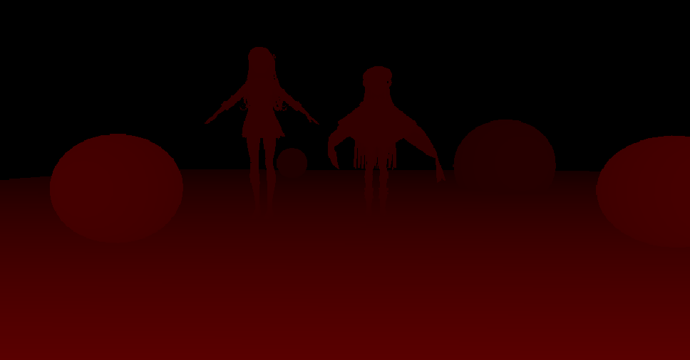
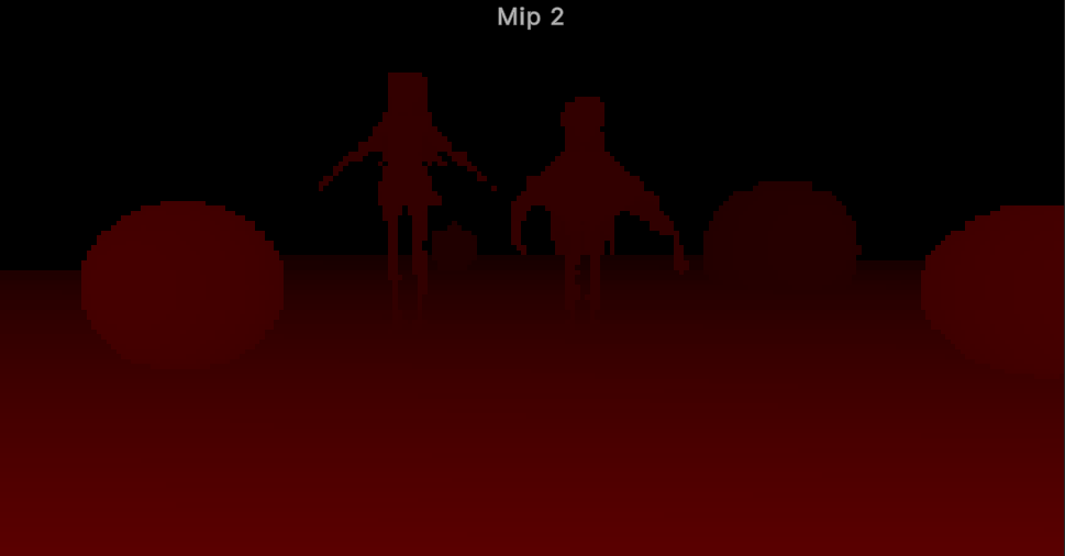
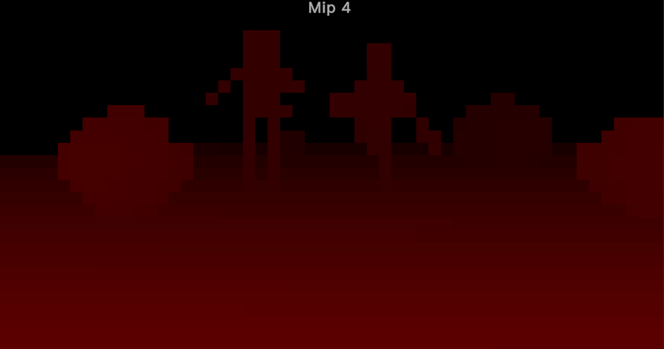
在生成的时候粗粒度的深度图保存到了另一个纹理中,为了简化在shader中迭代的代码,我将生成的粗粒度图拷贝到深度图的Mipmap中。得到的Hi-Z如下:
RayMarching的改变
在Shader中则需要动态管理采样的MipLevel,该算法大致的思想如下:
- 若是没有与当前层级的深度图相交则增加层级。
- 若是与当前层级相交则判断是否是粒度最细的层级。
- 若是粒度最细的层级则证明射线与场景相交,进行Shading;否则减小层级。
- 若减小到某一层级时判断不相交则回到第二步。
前面的变换到屏幕空间及DDA算法的准备相同,后面也同样使用DDA画线算法,不过每次都会根据当前的Hi-Z层级来计算一个因数,来增加步进距离,采样的MipLevel也根据上述的算法来实现。最后实现的代码如下:
float4 SSR2DRayMarchingWithHiz(
    float2 currPosSS, float2 endPosSS, float2 offsetSS,
    float3 currPosVS, float3 offsetVS,
    float currK, float offsetK,
    float stepDir, bool steep)
{
    const int marchingCount = _RayMarchingMaxDistance / _RayMarchingStep;
    float2 invWH = 1.f / float2(GetCameraTexWidth(), GetCameraTexHeight());
    float preZ = currPosVS.z / currK;

    int level = _HizStartLevel;

    [loop]
    for (int iii = 0; (currPosSS.x * stepDir < endPosSS.x * stepDir) && iii < marchingCount; ++iii) {
        float levelMulti = exp2(level);
        currPosSS += offsetSS * levelMulti, currPosVS.z += offsetVS.z * levelMulti, currK += offsetK * levelMulti;

        float2 uv = steep ? currPosSS.yx : currPosSS.xy;
        uv *= invWH;
        #if UNITY_UV_STARTS_AT_TOP
        uv.y = 1 - uv.y;    // 需要进行反转
        #endif
        float sceneZ = SAMPLE_DEPTH_TEXTURE_LOD(_HizTexture, sampler_point_clamp, uv, level);
        sceneZ = -LinearEyeDepth(sceneZ, _ZBufferParams);

        float minZ = preZ;
        // 通过 K 获得当前位置的深度
        //float maxZ = (currPosVS.z + 0.5f * currPosVS.z) / (currK + 0.5f * offsetK);
        float maxZ = currPosVS.z / currK;
        preZ = maxZ;
        [flatten]
        if (minZ > maxZ){
            SwapFloat(minZ, maxZ);
        }

        bool inRange = all(0 <= uv && uv <= 1);
        bool hit = maxZ >= sceneZ - _HitThreshold;
        [flatten]
        if (hit && inRange) {   // 击中物体
            [flatten]
            if (level <= _HizEndLevel) {    // 最后一层则直接返回
                [branch]
                if (minZ <= sceneZ) {
                    return GetCameraColor(uv);
                }
            }
            else {  // 不是最后一层则回退并减小MipMap层数
                currPosSS -= offsetSS * levelMulti, currPosVS.z -= offsetVS.z * levelMulti, currK -= offsetK * levelMulti;
                preZ = currPosVS.z / currK;
                --level;
            }
        }
        else {  // 若击中则提高MipMap的层数并提高步频
            level = min(_HizCount, level + 1);
        }
    }

    return float4(0, 0, 0, 1);
}
不过这里有一个地方我还是有点迷,那就是判断相交时的判断条件,先前没有使用Hi-Z我是用的判断条件是与使用Hi-Z那篇Paper相同的,但是使用之后使用相同的判断条件时反射的效果非常不好,现在使用的判断条件是看了其他大佬的文章后试出效果最好的。

 浙公网安备 33010602011771号