
DirectX RayTracing (2) 简易的3D场景及光照
DirectX RayTracing (2) 简易的3D场景及光照
该文章基于上一篇对 DX12 光追管线的基础介绍,若是没看过可以去看看。有了基本的光追框架,在其基础上实现各种功能就简单了许多。这次的目的是实现 3D 物体的绘制及简单的光照。接下来便列出需要修改的地方及对应的原理。
资源的绑定
首先便是需要我确定绘制一个 3D 物体所需要的资源,对于顶层加速结构及作为输出的纹理,同样作为 SRV 和 UAV 绑定到 Shader 中。为了实现基础的光照,在 Closest Hit Shader 中需要得到几何体的顶点信息,而光追管线不像图形光线通过输入布局(InputLayout)来绑定几何体的顶点及索引信息,因此我们需要自行将几何体的顶点和索引信息绑定到管线中,这里我将其作为StructuredBuffer绑定到管线中,具体的步骤就是将传给加速结构的顶点缓冲区与索引缓冲区作为 SRV 绑定到管线中。为了绘制一个 3D 物体需要光源信息、材质信息及相机的信息,这些作为常量缓冲区绑定到管线中,因此 Shader 中资源的布局如下:
struct CubeConstantBuffer
{
    float4 albedo;
};

struct SceneConstantBuffer
{
    // 生成光线使用的数据
    float4 cameraPosAndFocusDist;
    float4 viewportU;
    float4 viewportV;
    float4 lightColor;
    float4 lightDirAndGloss;
};

struct Vertex
{
    float3 position;
    float3 normal;
    float4 tangent;
    float3 biTangent;
    float2 texCoord;
};

// 场景中的几何数据
RaytracingAccelerationStructure gScene : register(t0);
StructuredBuffer<Vertex> gVertexBuffer : register(t1);
StructuredBuffer<uint3> gIndexBuffer : register(t2);

// 输出图像
RWTexture2D<float4> gOutput : register(u0);

// 全局常量缓冲区
ConstantBuffer<SceneConstantBuffer> gSceneCB : register(b0);
// 局部常量缓冲区
ConstantBuffer<CubeConstantBuffer> gCubeCB : register(b1);
这里使用了 SM5.0 的一个特性,常量缓冲区可以通过ConstantBuffer<>进行声明,模板中可填入内置类型或是自定义结构体。Shader 中资源布局对用的根签名如下:
m_LocalRootSig[0].InitAsConstants(1, sizeof(CubeConstantBuffer) / sizeof(uint32_t) + 1);
m_LocalRootSig.Finalize(L"RayTracingLocalRootSignature", D3D12_ROOT_SIGNATURE_FLAG_LOCAL_ROOT_SIGNATURE);
m_GlobalRootSig[RayTracingOutput].InitAsDescriptorRange(D3D12_DESCRIPTOR_RANGE_TYPE_UAV, 0, 1);  // RayTracingOutput
m_GlobalRootSig[AccelerationStructure].InitAsBufferSRV(0);  // 加速结构
m_GlobalRootSig[VertexData].InitAsBufferSRV(1);  // 顶点数据
m_GlobalRootSig[IndexData].InitAsBufferSRV(2);  // 索引数据
m_GlobalRootSig[SceneConstantBuffer].InitAsConstantBuffer(0);
m_GlobalRootSig.Finalize(L"RayTracingGlobalRootSignature");
这里只实现简单的光照,因此材质中只有物体的颜色,由于每个物体都对应一个材质。可行的管理方式有将材质作为常量缓冲区绑定到局部根签名中;或是作为StructuredBuffer绑定到全局根签名中,然后再局部根签名中设置索引。这里使用了第一种方法。
管线的配置
定义完所需的资源后,接下来便是要配置光追管线并创建 PSO。这里同样需要创建七个子对象,与上一次相同的子对象这里就不赘述了,需要更改的子对象只有一个,那就是局部根签名与 Shader 相关联的D3D12_SUBOBJECT_TO_EXPORTS_ASSOCIATION。上一次是将其绑定到 Ray Generation Shader 中,这次由于需要在 Closest Hit Shader 中使用局部根签名中的材质信息,因此需要将其关联到 Hit Group 中,具体的更改如下:
// 将局部根签名与 shader 相关联
D3D12_SUBOBJECT_TO_EXPORTS_ASSOCIATION localRootSigAssociation{};
localRootSigAssociation.pSubobjectToAssociate = &localSubobject;
localRootSigAssociation.NumExports = 1;
localRootSigAssociation.pExports = &s_HitGroupName; // Hit Group 的导出名
D3D12_STATE_SUBOBJECT localRootSigAssociationSubobject{};
localRootSigAssociationSubobject.Type = D3D12_STATE_SUBOBJECT_TYPE_SUBOBJECT_TO_EXPORTS_ASSOCIATION;
localRootSigAssociationSubobject.pDesc = &localRootSigAssociation;
subobjects.push_back(std::move(localRootSigAssociationSubobject));
Shader Table 的创建
最后一步便是创建 Shader Table 了,上面我将局部根签名绑定到了 Hit Group 中,因此 Hit Group Shader Table 中 的每一个 Shader Record 除了 Shader Identifier 外还需要包含一个常量缓冲区,由于后续需要更新 Shader Table 中的常量缓冲区,因此创建时我将其类型指定为 Upload。具体的步骤如下:
// 获取 Shader 的标识符
Microsoft::WRL::ComPtr<ID3D12StateObjectProperties> stateObjectProps{};
ASSERT_SUCCEEDED(m_RayTracingStateObject.As(&stateObjectProps));
void* rayGenShaderIdentifier = stateObjectProps->GetShaderIdentifier(Renderer::s_RayGenShaderName);
void* missShaderIdentifier = stateObjectProps->GetShaderIdentifier(Renderer::s_MissShaderName);
void* hitGroupIdentifier = stateObjectProps->GetShaderIdentifier(Renderer::s_HitGroupName);

// RayGeneration 着色器表
GpuBufferDesc rayGenShaderTableDesc{};
rayGenShaderTableDesc.m_Size = D3D12_SHADER_IDENTIFIER_SIZE_IN_BYTES;
rayGenShaderTableDesc.m_Stride = rayGenShaderTableDesc.m_Size;
rayGenShaderTableDesc.m_HeapType = D3D12_HEAP_TYPE_UPLOAD;
m_RayGenShaderTable.Create(L"RayGenShaderTable", rayGenShaderTableDesc, rayGenShaderIdentifier);
// Miss 着色器表
GpuBufferDesc missShaderTableDesc = rayGenShaderTableDesc;
missShaderTableDesc.m_Size = D3D12_SHADER_IDENTIFIER_SIZE_IN_BYTES;
missShaderTableDesc.m_Stride = missShaderTableDesc.m_Size;
m_MissShaderTable.Create(L"MissShaderTable", missShaderTableDesc, missShaderIdentifier);
// Hit 着色器表
GpuBufferDesc hitShaderTableDesc = rayGenShaderTableDesc;
auto size = D3D12_SHADER_IDENTIFIER_SIZE_IN_BYTES + Math::AlignUp(sizeof(CubeConstantBuffer), D3D12_CONSTANT_BUFFER_DATA_PLACEMENT_ALIGNMENT);
hitShaderTableDesc.m_Size = Math::AlignUp(size, D3D12_RAYTRACING_SHADER_RECORD_BYTE_ALIGNMENT);
hitShaderTableDesc.m_Stride = hitShaderTableDesc.m_Size;
std::vector<uint8_t> hitShaderTableData(hitShaderTableDesc.m_Size);
memcpy(hitShaderTableData.data(), hitGroupIdentifier, D3D12_SHADER_IDENTIFIER_SIZE_IN_BYTES);
m_HitShaderTable.Create(L"HitShaderTable", hitShaderTableDesc, hitShaderTableData.data());
在每次调用DispatchRays之前,还需要更新 Shader Table 中的常量缓冲区,这里我是用 ImGui 来控制物体的颜色:
CubeConstantBuffer cubeCB{};
cubeCB.albedo = Math::Vector4{imgui.cubeAlbedo};
g_Renderer.m_HitShaderTable.Update(&cubeCB, sizeof(CubeConstantBuffer), D3D12_SHADER_IDENTIFIER_SIZE_IN_BYTES);
创建完 Shader Table 后 CPU 端的配置也就完成了,加速结构的创建及管线的启动都与上一篇文章一模一样,唯一的区别就是加速结构使用的顶点缓冲区和索引缓冲区中的数据换为了立方体的数据。
Shader 代码
这里使用的 Miss Shader 与上次相同,同样是放回一个背景颜色。Ray Generation Shader 中生成光线的方法使用了 Ray Tracing In One Weekend 中的方法,及通过相机的视场角和相机的位置计算出视口最左上角的像素的世界空间的坐标,然后根据输出纹理的大小计算出每个像素的偏移量,具体步骤如下:
float focusDist = 10;	// 大于0即可
auto h = std::tan(m_Camera->GetFovY() * .5f);
auto viewportHeight = 2 * h * focusDist;
float viewportWidth = viewportHeight * (float(width) / height);
SceneConstantBuffer sceneCB{};
sceneCB.cameraPosAndFocusDist = Math::Vector4{m_Camera->GetPosition(), focusDist};
sceneCB.viewportU = Math::Vector4{m_Camera->GetRightAxis() * viewportWidth};
sceneCB.viewportV = Math::Vector4{-m_Camera->GetUpAxis() * viewportHeight};
sceneCB.lightColor = Math::Vector4{imgui.lightColor, 0};
sceneCB.lightDirAndGloss = Math::Vector4{imgui.lightDir.Normalized(), float(imgui.cubeGloss)};
RayDesc GetRay(int2 index)
{
    uint2 dimension = DispatchRaysDimensions().xy;	// 输出的大小
    float3 viewportU = gSceneCB.viewportU.xyz;
    float3 viewportV = gSceneCB.viewportV.xyz;
    float3 front = normalize(cross(viewportV, viewportU));

    float3 pixelDeltaU = viewportU / dimension.x;	// 每个像素的偏移量
    float3 pixelDeltaV = viewportV / dimension.y;

    float3 cameraPos = gSceneCB.cameraPosAndFocusDist.xyz;
    float focusDist = gSceneCB.cameraPosAndFocusDist.w;
    float3 startPixelCenter = cameraPos + front * focusDist - (viewportU + viewportV) * 0.5f;
    startPixelCenter += (pixelDeltaU + pixelDeltaV) * 0.5f;

    float3 pixelSample = startPixelCenter + index.x * pixelDeltaU + index.y * pixelDeltaV;

    RayDesc ray;
    ray.Origin = cameraPos;
    ray.Direction = normalize(pixelSample - ray.Origin);
    ray.TMin = 0.001f;
    ray.TMax = 10000.0f;
    return ray;
}

[shader("raygeneration")]
void RaygenShader()
{
    RayDesc ray = GetRay(DispatchRaysIndex().xy);

    RayPayload payload;
    payload.color = float4(0, 0, 0, 1);
    TraceRay(gScene, RAY_FLAG_CULL_BACK_FACING_TRIANGLES, ~0, 0, 1, 0, ray, payload);
    gOutput[DispatchRaysIndex().xy] = payload.color;
}
接下来便是 Closest Hit Shader,首先需要获得射线击中的三角形的三个顶点,这里可以通过内置函数PrimitiveIndex还获取击中的三角形的索引,然后在索引缓冲区中获取其索引,并通过索引获取顶点即可:
StructuredBuffer<Vertex> gVertexBuffer : register(t1);
StructuredBuffer<uint3> gIndexBuffer : register(t2);

uint3 indices = gIndexBuffer[PrimitiveIndex()];
Vertex vertices[3] = {
    gVertexBuffer[indices[0]],
    gVertexBuffer[indices[1]],
    gVertexBuffer[indices[2]]
};
这里需要手动用传入的顶点属性进行的插值来获取交点的信息:
Vertex GetHitAttributes(Vertex vertices[3], float2 barycentrics)
{
    float3 barycentrics3 = float3(1 - barycentrics.x - barycentrics.y, barycentrics.x, barycentrics.y);
    Vertex attributes;
    attributes.position = vertices[0].position * barycentrics3.x + vertices[1].position * barycentrics3.y + vertices[2].position * barycentrics3.z;
    attributes.normal = normalize(vertices[0].normal * barycentrics3.x + vertices[1].normal * barycentrics3.y + vertices[2].normal * barycentrics3.z);
    attributes.tangent = normalize(vertices[0].tangent * barycentrics3.x + vertices[1].tangent * barycentrics3.y + vertices[2].tangent * barycentrics3.z);
    attributes.biTangent = normalize(vertices[0].biTangent * barycentrics3.x + vertices[1].biTangent * barycentrics3.y + vertices[2].biTangent * barycentrics3.z);
    attributes.texCoord = vertices[0].texCoord * barycentrics3.x + vertices[1].texCoord * barycentrics3.y + vertices[2].texCoord * barycentrics3.z;
    return attributes;
}

Vertex attributes = GetHitAttributes(vertices, attrs.barycentrics);
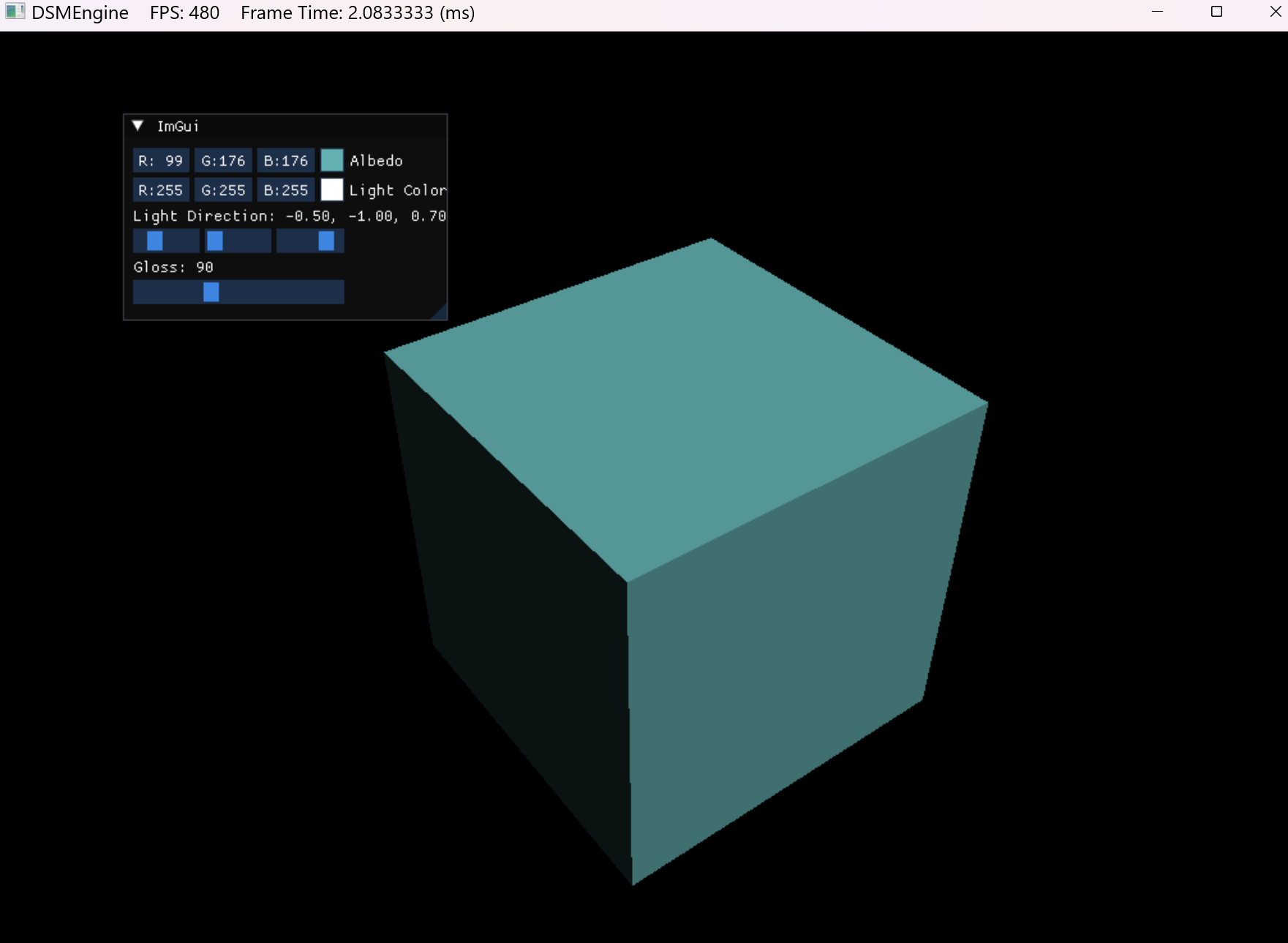
最后从常量缓冲区中获取光照信息并使用 Blinn-Phong 模型计算光照,并将其写入输出纹理即可:
float3 lightDir = -normalize(gSceneCB.lightDirAndGloss.xyz);
float3 lightColor = gSceneCB.lightColor.rgb;
float3 halfDir = normalize(lightDir - normalize(WorldRayDirection()));
float gloss = gSceneCB.lightDirAndGloss.w;

float4 albedo = gCubeCB.albedo;
float3 diffuse = lightColor * max(0, dot(lightDir, attributes.normal));
float3 specular = lightColor * pow(max(0, dot(halfDir, attributes.normal)), gloss);
float3 col = saturate(diffuse + specular + 0.1);
col *= albedo.rgb;

// 获取重心坐标
payload.color = float4(col, albedo.a);
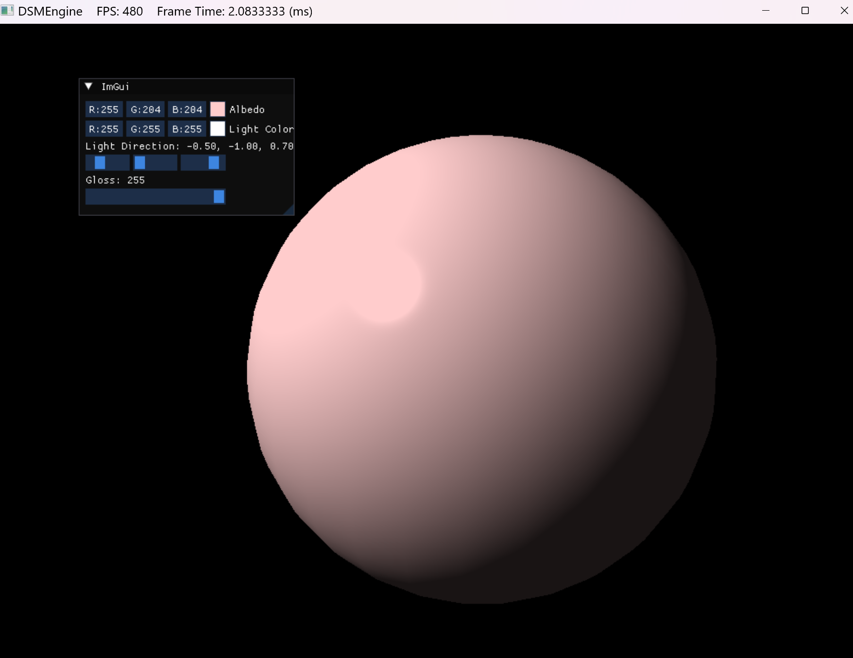
最后得到的输出如下:
将几何体换成球:

 浙公网安备 33010602011771号