羽夏看Linux内核——引导启动(上)
写在前面
此系列是本人一个字一个字码出来的,包括示例和实验截图。如有好的建议,欢迎反馈。码字不易,如果本篇文章有帮助你的,如有闲钱,可以打赏支持我的创作。如想转载,请把我的转载信息附在文章后面,并声明我的个人信息和本人博客地址即可,但必须事先通知我。
你如果是从中间插过来看的,请仔细阅读 羽夏看Linux系统内核——简述 ,方便学习本教程。
Linux 0.11 介绍
Linux 0.11 写于 1991 年年底,那时很多计算机都是通过软盘启动的,故该代码是从软盘启动的。目前操作系统启动都是通过硬盘,下面我们介绍它的启动流程,仿制的时候改为从硬盘启动。
在 16 位模式下,内存的使用是十分有限的,我再拿之前的表格:

从图中可以看出,我们可以在实模式下可以随便动的内存区域是0x00500-0x9FBFF。注意,这里可以随便动是指我不影响实模式所用的东西的前提下可以动的区域。0x07C00-0x07DFF是BIOS把我们的第一个扇区加载到内存的代码,如果我们需要第一扇区的代码,这块也不能乱动。
也就是说,在 16 位实模式下,我们拉起内核需要精打细算的利用好我们能够用的内存,也不能在执行代码过程中覆盖到我们所需的数据。说完这些,我们来看内核代码。
注:在之后的教程,我说内核源码所在目录,我会用
linuxsrc表示,请悉知。
bootsect
学了之前的内容,我们知道BIOS会加载第一扇区的代码,而这个代码对应了linuxsrc/boot文件夹下的bootsect.s文件,我们打开看一下,首先看到了注释:
! SYS_SIZE is the number of clicks (16 bytes) to be loaded.
! 0x3000 is 0x30000 bytes = 196kB, more than enough for current
! versions of linux
!
SYSSIZE = 0x3000
!
!   bootsect.s      (C) 1991 Linus Torvalds
!
! bootsect.s is loaded at 0x7c00 by the bios-startup routines, and moves
! iself out of the way to address 0x90000, and jumps there.
!
! It then loads 'setup' directly after itself (0x90200), and the system
! at 0x10000, using BIOS interrupts.
对于as86汇编语法来说,在!或者;之后的表示注释。这段注释告诉我们,bootsect.s会被加载到0x7c00这个地址,那这个代码必定在第一扇区。之后这块代码会移动到0x90000地址并跳转到那里,然后通过BIOS中断拉起setup到0x10000。
与此同时,为了更加直观的学习,我们可以使用已有的镜像看看情况。现在 Linux 0.11 版本很难直接编译通过,我调了半天虽然编译成功了,但Bochs加载不了。不过我们网上已经有对应的镜像,首先给个链接:
http://www.oldlinux.org/Linux.old/bochs/
其实这些包个包是给在 Win 上学习准备的,这对于我们在 Deepin 等 Linux 发行版上进行学习就不太方便,这个配置文件没法直接使用,会报错。不过没关系,我给制作了一个完整的包,并放到我的代码仓库:
- Gitee : https://gitee.com/wingsummer/linuxbochs
- Gitea : https://code.gitlink.org.cn/wingsummer/Linuxbochs
你只需要clone一下到你的学习文件夹下即可。都是学内核的同志了,git clone应该都会,这里就不赘述了。如果要启动虚拟机,只需执行startLinux.sh脚本即可。下面我们来看看开头的代码:
BOOTSEG  = 0x07c0   ! original address of boot-sector
INITSEG  = 0x9000   ! we move boot here - out of the way
SETUPSEG = 0x9020   ! setup starts here

start:
    mov ax,#BOOTSEG
    mov ds,ax
    mov ax,#INITSEG
    mov es,ax
    mov cx,#256
    sub si,si
    sub di,di
    rep
    movw
    jmpi go,INITSEG
BOOTSEG是0x07c0,也就是被BIOS初始加载的地址。你可能会有疑问。 被BIOS初始加载的地址不是0x7c00吗? 是的,但是这个是被加载到段寄存器的,如果偏移是0,且被16整除,只需要把地址地板除以16就是我们想要得到的结果。
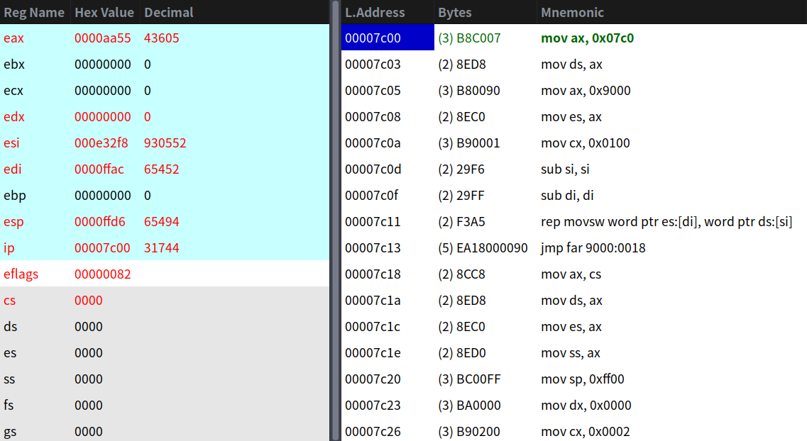
这段就是拷贝bootsect.s程序到0x90000这个地址。加载程序一共有512个字节,由于一次移动一个字,所以给cx赋值256即可。我们可以看看Bochs的内容:
虽然有了 GUI ,但不能完全被代替,你还得需要知道一些基本的调试命令,这个不是本教程的重点,请自行补充。
拷贝完后,并执行跨段跳转后的状态:

我们继续:
go: mov ax,cs
    mov ds,ax
    mov es,ax
! put stack at 0x9ff00.
    mov ss,ax
    mov sp,#0xFF00  ! arbitrary value >>512
这块是使用cs初始化段寄存器和栈空间,由于十分简单就不赘述了。
! load the setup-sectors directly after the bootblock.
! Note that 'es' is already set up.

load_setup:
    mov dx,#0x0000             ! drive 0, head 0
    mov cx,#0x0002             ! sector 2, track 0
    mov bx,#0x0200             ! address = 512, in INITSEG
    mov ax,#0x0200+SETUPLEN    ! service 2, nr of sectors
    int 0x13                   ! read it
    jnc ok_load_setup          ! ok - continue
    mov dx,#0x0000
    mov ax,#0x0000             ! reset the diskette
    int 0x13
    j load_setup
0x13中断是一个服务,用来对磁盘进行操作。我们简单介绍一下各寄存器的功能。这块代码是读取扇区,如果使用该功能,需要AH=0x02,这也是为什么mov ax,#0x0200+SETUPLEN要加个0x0200。
| 寄存器 | 作用 |
|---|---|
| AL | 扇区数 |
| CH | 柱面 |
| CL | 扇区 |
| DH | 磁头 |
| DL | 驱动器(00H - 7FH 为软盘;80H - 0FFH 为硬盘) |
| ES:BX | 缓冲区的地址 |
既然是读取操作,必然需要知道读取结果。如果CF = 0,则表示成功,此时AH = 00H,AL = 传输的扇区数。如果失败,AH是状态码。有关状态码这事情我就不赘述了,自己可以从网络进行查阅。
此时ES = 9000H,而读取时BX = 0x0200,所以读取后被放到0x90200这个地址。如果读取成功,就会跳转到ok_load_setup这个标签,失败重置磁盘状态(AH = 0调用),重试直到成功。执行完int 0x13指令后,我们看看结果:
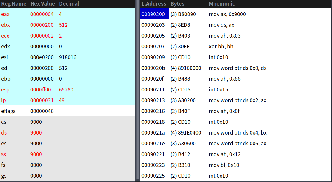
然后我们看看setup.s开头几行汇编:
mov ax,#INITSEG ! this is done in bootsect already, but...
mov ds,ax
mov ah,#0x03    ! read cursor pos
xor bh,bh
int 0x10        ! save it in known place, con_init fetches
mov [0],dx  ! it from 0x90000.
可以看到完全一致。我们接着继续:
ok_load_setup:

! Get disk drive parameters, specifically nr of sectors/track

    mov dl,#0x00
    mov ax,#0x0800      ! AH=8 is get drive parameters
    int 0x13
    mov ch,#0x00
    seg cs
    mov sectors,cx
    mov ax,#INITSEG
    mov es,ax

! Print some inane message

    mov ah,#0x03            ! read cursor pos
    xor bh,bh
    int 0x10

    mov cx,#24
    mov bx,#0x0007          ! page 0, attribute 7 (normal)
    mov bp,#msg1
    mov ax,#0x1301          ! write string, move cursor
    int 0x10
当AH = 0x08时,调用int 0x13是获取磁盘大小信息。其中DL为驱动器,如果成功CF = 0,BL会获得1-4的数值,为磁盘大小,含义如下:
| BL 值 | 含义 |
|---|---|
| 1 | 360 KB |
| 2 | 1.2 MB |
| 3 | 720 KB |
| 4 | 1.44 MB |
与此同时,CH代表柱面数的低八位;CL的高两位代表柱面数的高两位,CL剩余的位代表扇区数;DH代表柱头数;DL代表驱动器数;ES:DI指向的是磁盘驱动器参数表地址。
在调用完int 0x13之后,将区块的扇区数目放到了sectors中。紧接着后面我们又遇到了一个中断int 0x10,这个是用于显示的服务,可以往屏幕上写字符串操作。将msg1写到屏幕上,我们来看看这是什么:
msg1:
    .byte 13,10
    .ascii "Loading system ..."
    .byte 13,10,13,10
回车键的ASCII是13,换行键的ASCII是10,如果组合起来就是回车换行,就是C/C++的\n。
接下来我们继续下一部分代码:
! ok, we've written the message, now
! we want to load the system (at 0x10000)

    mov ax,#SYSSEG
    mov es,ax           ! segment of 0x010000
    call read_it
    call kill_motor
这部分就是加载system模块了,system模块就是内核模块,包含库模块lib、内存管理模块mm、内核模块kernel、main.c和head.s程序,后面将会详细介绍。read_it就是读取函数,将模块读取到0x010000这个地址。kill_motor函数是关闭驱动器马达,以知道驱动器状态。为什么可以看注释:
/*
 * This procedure turns off the floppy drive motor, so
 * that we enter the kernel in a known state, and
 * don't have to worry about it later.
 */
 kill_motor:
我们来粗略简单看看read_it函数:
read_it:
        mov ax,es
        test ax,#0x0fff
die:·   jne die             ! es must be at 64kB boundary
        xor bx,bx           ! bx is starting address within segment
rp_read:
        mov ax,es
        cmp ax,#ENDSEG      ! have we loaded all yet?
        jb ok1_read
        ret
ok1_read:
        seg cs
        mov ax,sectors
        sub ax,sread
        mov cx,ax
        shl cx,#9
        add cx,bx
        jnc ok2_read
        je ok2_read
        xor ax,ax
        sub ax,bx
        shr ax,#9
ok2_read:
        call read_track
        mov cx,ax
        add ax,sread
        seg cs
        cmp ax,sectors
        jne ok3_read
        mov ax,#1
        sub ax,head
        jne ok4_read
        inc track
ok4_read:
        mov head,ax
        xor ax,ax
ok3_read:
        mov sread,ax
        shl cx,#9
        add bx,cx
        jnc rp_read
        mov ax,es
        add ax,#0x1000
        mov es,ax
        xor bx,bx
        jmp rp_read

read_track:
        push ax
        push bx
        push cx
        push dx
        mov dx,track
        mov cx,sread
        inc cx
        mov ch,dl
        mov dx,head
        mov dh,dl
        mov dl,#0
        and dx,#0x0100
        mov ah,#2
        int 0x13
        jc bad_rt
        pop dx
        pop cx
        pop bx
        pop ax
        ret
这些都是对磁盘进行大量读写的操作,以0x100字节作为块一次一次读取。我们来看一下执行结果:
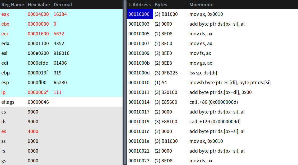
剩下的最后一块bootsect.s程序:
! After that we check which root-device to use. If the device is
! defined (!= 0), nothing is done and the given device is used.
! Otherwise, either /dev/PS0 (2,28) or /dev/at0 (2,8), depending
! on the number of sectors that the BIOS reports currently.

    seg cs
    mov ax,root_dev
    cmp ax,#0
    jne root_defined
    seg cs
    mov bx,sectors
    mov ax,#0x0208      ! /dev/ps0 - 1.2Mb
    cmp bx,#15
    je root_defined
    mov ax,#0x021c      ! /dev/PS0 - 1.44Mb
    cmp bx,#18
    je root_defined
undef_root:
    jmp undef_root
root_defined:
    seg cs
    mov root_dev,ax

! after that (everyting loaded), we jump to
! the setup-routine loaded directly after
! the bootblock:

    jmpi 0,SETUPSEG
root_dev是一个变量,它指向一个字大小的宏ROOT_DEV,它的值为0x306。
root_dev:
    .word ROOT_DEV
为什么是这个值呢?如果该值为0,根文件系统设备与引导使用同样的软驱设备;如果是0x301,则为第一个硬盘的第一个分区上,这个被称为设备号。设备号 = 主设备号 * 256 + 次设备号,举个例子:
- 0x300 - /dev/hd0 代表第一个硬盘
- 0x301 - /dev/hd1 代表第一个硬盘的第一个分区
- ……
- 0x304 - /dev/hd4 代表第一个硬盘的第四个分区
- 0x305 - /dev/hd5 代表第二个硬盘
- ……
于是该内核使用的是第二个硬盘的第一个分区,作为根文件系统设备。
接下来两个cmp可能看不懂,咱们给个解释:sectors是我们之前保存的每磁道扇区数目,如果是 15 ,那么就是 1.2 MB 的驱动器;如果是 18 ,那么就是 1.44 MB 的,也就是引导驱动器的设备号。如果正常找到,将会执行jmpi 0,SETUPSEG,该部分程序结束;否则,直接死循环。
setup
下面开始setup.s代码的讲解,这个程序十分重要,它是操作系统加载程序。先看开头:
! ok, the read went well so we get current cursor position and save it for
! posterity.

    mov ax,#INITSEG ! this is done in bootsect already, but...
    mov ds,ax
    mov ah,#0x03    ! read cursor pos
    xor bh,bh
    int 0x10        ! save it in known place, con_init fetches
    mov [0],dx      ! it from 0x90000.

! Get memory size (extended mem, kB)

    mov ah,#0x88
    int 0x15
    mov [2],ax

! Get video-card data:

    mov ah,#0x0f
    int 0x10
    mov [4],bx      ! bh = display page
    mov [6],ax      ! al = video mode, ah = window width

! check for EGA/VGA and some config parameters

    mov ah,#0x12
    mov bl,#0x10
    int 0x10
    mov [8],ax
    mov [10],bx
    mov [12],cx

! Get hd0 data

    mov ax,#0x0000
    mov ds,ax
    lds si,[4*0x41]
    mov ax,#INITSEG
    mov es,ax
    mov di,#0x0080
    mov cx,#0x10
    rep
    movsb

! Get hd1 data

    mov ax,#0x0000
    mov ds,ax
    lds si,[4*0x46]
    mov ax,#INITSEG
    mov es,ax
    mov di,#0x0090
    mov cx,#0x10
    rep
    movsb

! Check that there IS a hd1 :-)

    mov ax,#0x01500
    mov dl,#0x81
    int 0x13
    jc no_disk1
    cmp ah,#3
    je is_disk1
no_disk1:
    mov ax,#INITSEG
    mov es,ax
    mov di,#0x0090
    mov cx,#0x10
    mov ax,#0x00
    rep
    stosb
这块代码首先获取了光标位置,然后作为一个字存到了0x90000。同理,获取了扩展内存的大小、一些显示类的信息和硬盘参数列表。
硬盘参数表是什么?在PC机中BIOS设定的中断向量表中int 0x41的中断向量位置存放的并不是中断程序的地址,而是第一个硬盘的基本参数表。对于BIOS来说,这里存放着硬盘参数表阵列的首地址0xFE401。第二个硬盘的基本参数表入口地址存于int 0x46中断向量位置处。每个硬盘参数表有16个字节大小。这些是硬件的相关知识,了解明白即可。
接下来就是让你激动的时刻,开始进入保护模式。先看第一部分代码:
! now we want to move to protected mode ...

    cli             ! no interrupts allowed !

! first we move the system to it's rightful place

    mov ax,#0x0000
    cld             ! 'direction'=0, movs moves forward
do_move:
    mov es,ax       ! destination segment
    add ax,#0x1000
    cmp ax,#0x9000
    jz end_move
    mov ds,ax       ! source segment
    sub di,di
    sub si,si
    mov cx,#0x8000
    rep
    movsw
    jmp do_move
end_move:
首先使用cli指令屏蔽中断,准备开始乾坤大挪移,将system模块移动到想要的位置(内存0地址处)。
但是0地址附近正是BIOS相关数据区,我们再把上面的表格拿下来:
也就是说,原来的BIOS的中断和数据被覆盖了,也就是被舍弃掉了。由于当时system假设模块的最大长度不会超过0x80000,也就是512 KB,即末尾不会超过0x90000这个地址。
移动完后,就开始进入保护模式的准备工作了。
在Intel的保护模式下,段描述符存在于GDT和IDT表中(LDT不使用)。段寄存器需要GDT表,而调用中断需要IDT表,所以我们需要设置这两张表:
! then we load the segment descriptors

end_move:
    mov ax,#SETUPSEG     ! right, forgot this at first. didn't work :-)
    mov ds,ax
    lidt idt_48          ! load idt with 0,0
    lgdt gdt_48          ! load gdt with whatever appropriate
我们来看看这所谓的idt_48和gdt_48到底是啥:
idt_48:
    .word 0             ! idt limit=0
    .word 0,0           ! idt base=0L

gdt_48:
    .word 0x800         ! gdt limit=2048, 256 GDT entries
    .word 512+gdt,0x9   ! gdt base = 0X9xxxx
下一步开启A20地址线,开始蜕变:
! that was painless, now we enable A20

    call empty_8042
    mov al,#0xD1        ! command write
    out #0x64,al
    call empty_8042
    mov al,#0xDF        ! A20 on
    out #0x60,al
    call empty_8042
这里得注意一下:A20地址线并不是打开保护模式的关键,只是在保护模式下,不打开A20地址线,你将无法访问到所有的内存。 这个又是为了保持兼容性出的幺蛾子。empty_8042这个函数的作用是测试8042状态寄存器。这块代码涉及硬件的相关东西太多,这里就简单介绍,感兴趣可自行科普。
! well, that went ok, I hope. Now we have to reprogram the interrupts :-(
! we put them right after the intel-reserved hardware interrupts, at
! int 0x20-0x2F. There they won't mess up anything. Sadly IBM really
! messed this up with the original PC, and they haven't been able to
! rectify it afterwards. Thus the bios puts interrupts at 0x08-0x0f,
! which is used for the internal hardware interrupts as well. We just
! have to reprogram the 8259's, and it isn't fun.

    mov al,#0x11        ! initialization sequence
    out #0x20,al        ! send it to 8259A-1
    .word 0x00eb,0x00eb ! jmp $+2, jmp $+2
    out #0xA0,al        ! and to 8259A-2
    .word 0x00eb,0x00eb
    mov al,#0x20        ! start of hardware int's (0x20)
    out #0x21,al
    .word 0x00eb,0x00eb
    mov al,#0x28        ! start of hardware int's 2 (0x28)
    out #0xA1,al
    .word 0x00eb,0x00eb
    mov al,#0x04        ! 8259-1 is master
    out #0x21,al
    .word 0x00eb,0x00eb
    mov al,#0x02        ! 8259-2 is slave
    out #0xA1,al
    .word 0x00eb,0x00eb
    mov al,#0x01        ! 8086 mode for both
    out #0x21,al
    .word 0x00eb,0x00eb
    out #0xA1,al
    .word 0x00eb,0x00eb
    mov al,#0xFF        ! mask off all interrupts for now
    out #0x21,al
    .word 0x00eb,0x00eb
    out #0xA1,al
这块代码相当奇奇怪怪。这个是对中断重新编程,放到Intel保留中断之后。这个又涉及硬件层面的东西,感兴趣自行科普825A芯片的相关知识。
这些代码看起来真没劲,生涩而且难看。不过所幸的是,我们终于可以真正的踏入保护模式了:
! Well, now's the time to actually move into protected mode. To make
! things as simple as possible, we do no register set-up or anything,
! we let the gnu-compiled 32-bit programs do that. We just jump to
! absolute address 0x00000, in 32-bit protected mode.

    mov ax,#0x0001  ! protected mode (PE) bit
    lmsw ax         ! This is it!
    jmpi 0,8        ! jmp offset 0 of segment 8 (cs)
我们先看一张图:
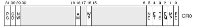
CR0的最后一位PE,控制着是否开启保护模式,如果置1,则么表示开启,此时CPU将开始进入全新的模式。但为什么用lmsw ax加载程序状态字的形式进行而不直接用mov cr0,ax呢?这又是该死的历史的包袱,仅仅是为了兼容罢了。
有关引导启动还剩最后一块,剩余的部分将会在下一篇进行。
练习与思考
本节的答案将会在下一节进行讲解,务必把本节练习做完后看下一个讲解内容。不要偷懒,实验是学习本教程的捷径。
俗话说得好,光说不练假把式,如下是本节相关的练习。如果练习没做成功,就不要看下一节教程了。
- 绘制执行进入保护模式的时候的内存布局状态。
- 用表格的形式展示
setup.s程序在内存中保存的数据。 .word 0x00eb,0x00eb的作用是啥?- 介绍到最后的
jmpi 0,8代码最终跳到了哪个地址?为什么?
下一篇


本文来自博客园,作者:寂静的羽夏 ,一个热爱计算机技术的菜鸟
转载请注明原文链接:https://www.cnblogs.com/wingsummer/p/16576792.html

 浙公网安备 33010602011771号