zynq linux开发笔记
Zynq linux开发笔记
1 petalinux
1.1 petalinux命令
1.1.1 工程创建
创建工程:
petalinux-create -t project -n vanjee --template zynq

导入/配置工程硬件信息:
petalinux-config --get-hw-description ../linux_base.sdk
1.1.2 组件配置
配置全部:
petalinux-config

配置uboot:
petalinux-config -c u-boot

配置设备树:
petalinux-config -c device-tree

配置内核:
petalinux-config -c kernel

配置rootfs:
petalinux-config -c rootfs
1.1.3 组件编译
编译全部:
petalinux-build

编译uboot:
petalinux-build -c u-boot

编译设备树:
petalinux-build -c device-tree
[注]:如果不是第一次编译设备树,即使修改了设备树执行上述命令也不会生成dtb文件,这时应先执行:
petalinux-build -c device-tree -x cleansstate
清理编译状态后再编译设备树。

编译内核:
petalinux-build -c kernel

编译根文件系统:
petalinux-build -c rootfs

编译工具链,可以独立编译应用:
petalinux-build -c meta-toolchain
或者使用:
petalinux-build --sdk,petalinux-package --sysroot
命令编译出交叉编译工具链,这样只会在 images/linux/sdk文件夹下就生成了编译工具和sysroot。

如果编译过程中出现异常 , 下一次编译的时候可以用:
petalinux-build -x mrproper
清除之后重新编译
1.1.4 生成BOOT文件
仅打包fsbl、pl的bit流、u-boot:
petalinux-package --boot --fsbl ./images/linux/zynq_fsbl.elf --fpga --u-boot --force

仅打包fsbl、pl的bit流、u-boot和kernel:
petalinux-package --boot --fsbl ./images/linux/zynq_fsbl.elf --fpga --u-boot --kernel --force

如需将根文件系统一起打包:
petalinux-package --boot --u-boot --kernel --add images/linux/rootfs.jffs2 --offset <partition offset given for jffs2>
例如:
petalinux-package --boot --fsbl ./images/linux/zynq_fsbl.elf --fpga --u-boot --kernel --add images/linux/rootfs.jffs2 --offset 0x00fa0000 --force
1.1.5 常见错误
1.1.5.1 bb.data_smart.ExpansionError: Failure expanding variable do_compile[file-checksums]
【错误截图】:
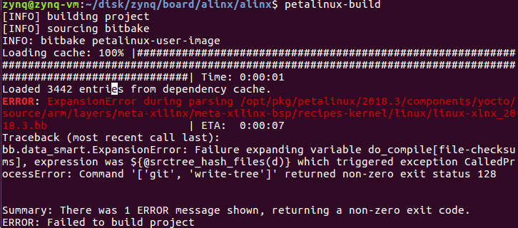
【错误原因】
petalinux 2018.3编译时由于某种原因(尚未可知),删除了<project_root-path>/build/downloads目录,导致编译时找不到git版本库,查看<project_root-path>/build/bitbake-cookerdaemon.log,可以证实:

【解决办法】
重新建立个测试工程,编译之后将其<project_root-path>/build/downloads拷贝到目标工程对应的文件夹<project_root-path>/build/下,再重新编译目标工程即可。
1.1.6 petalinux常用配置
1.1.6.1 源码保留
petalinux 2018.3 编译完成自动删除,如果想保留,可以在<project_root-path>/project-spec/meta-user/conf/petalinuxbsp.conf中添加以下内容,重新config并build工程即可:
RM_WORK_EXCLUDE += "linux-xlnx"
RM_WORK_EXCLUDE += "u-boot-xlnx"
1.1.6.2 自定义bootargs和root设备
如需在uboot启动时自定义bootargs,则需在petalinux-config时使能设备树自动生成并取消bootargs的自动生成,如下所示:
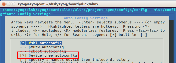
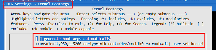
然后输入自定义的bootargs即可。
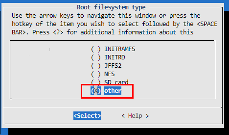
若需在uboot启动时自定义root设备,则需在则需在petalinux-config时选择Root filesystem type为other,如下图所示:
常用bootargs:
从flash启动:
setenv bootargs "console=ttyPS0,115200 earlyprintk rootfstype=jffs2 root=/dev/mtdblock3 rw rootwait"

从SD卡(单分区)启动:
setenv bootargs "console=ttyPS0,115200 earlyprintk root=/dev/mmcblk0 rw rootwait"

从initramfs(内核中含initramfs)启动:
setenv bootargs "console=ttyPS0,115200 earlyprintk"
1.2 常用文件路径
设备树:
<project_root-path>/components/plnx_workspace/device-tree/device-tree/

system-user.dtsi:
<project_root-path>/project-spec/meta-user/recipes-bsp/device-tree/files

uboot源码:
<project_root-path>/build/tmp/work/plnx_zynq7-xilinx-linux-gnueabi/u-boot-xlnx/v2018.01-xilinx-v2018.3+gitAUTOINC+d8fc4b3b70-r0/git

uboot配置文件.config:
<project_root-path>/build/tmp/work/plnx_zynq7-xilinx-linux-gnueabi/u-boot-xlnx/v2018.01-xilinx-v2018.3+gitAUTOINC+d8fc4b3b70-r0/build/.config
eg:
cp ~/disk/zynq/board/tst/tst/build/tmp/work/plnx_zynq7-xilinx-linux-gnueabi/u-boot-xlnx/v2018.01-xilinx-v2018.3+gitAUTOINC+d8fc4b3b70-r0/build/.config ~/disk/zynq/board/alinx/alinx/build/tmp/work/plnx_zynq7-xilinx-linux-gnueabi/u-boot-xlnx/v2018.01-xilinx-v2018.3+git999-r0/u-boot-xlnx-v2018.01-xilinx-v2018.3+git999/

内核源码:
<project_root-path>/build/tmp/work-shared/plnx-zynq7/kernel-source
1.3 uboot快捷命令
1.3.1 快捷指令1
setenv ipaddr 192.168.8.138
setenv serverip 192.168.8.177
setenv bootargs "console=ttyPS0,115200 earlyprintk rootfstype=jffs2 root=/dev/mtdblock3 rw rootwait"
setenv update_all "tftpboot 0x10000000 BOOT.BIN && sf probe 0 0 && sf erase 0 0x2000000 && sf write 0x10000000 0 0x2000000"
setenv update_boot "tftpboot 0x10000000 BOOT.BIN && sf probe 0 0 && sf erase 0 0x1E0000 && sf write 0x10000000 0 0x1E0000"
setenv update_rfs "tftpboot 0x10000000 rootfs.jffs2 && sf probe 0 0 && sf erase 0x700000 0x01900000 && sf write 0x10000000 0x700000 0x01900000"
setenv update_core "tftpboot 0x10000000 image.ub && sf probe 0 0 && sf erase 0x200000 0xA00000 && sf write 0x10000000 0x200000 0xA00000"
setenv pri_dtb "tftpboot 0x10000000 system.dtb && fdt addr 0x10000000 && fdt print"
setenv tst_core "tftpboot 0x10000000 image.ub && tftpboot 0x12000000 system.dtb && bootm 0x10000000 - 0x12000000"
setenv tst_corez "tftpboot 0x10000000 zImage && tftpboot 0x12000000 system.dtb && bootz 0x10000000 - 0x12000000"
saveenv
1.3.2 其它指令
1.3.2.1 uboot查看设备树指令
tftp加载设备树到内存地址0x10000000:
tftpboot 0x10000000 system.dtb

设置fdt地址为0x10000000:
fdt addr 0x10000000

查看设备树:
仅查看当前层:fdt list <path> [<prop>] - Print one level starting at <path>
查看当前层及子目录:fdt print <path> [<prop>] - Recursive print starting at <path>
例如:
fdt list /amba/spi@e000d000
fdt print /amba/spi@e000d000
2 zinux_cc
2.1 相关脚本
2.1.1 newproj.sh
功能:创建项目
代码:
#!/bin/sh

#0 参数合法性校验
#eg:./newproj.sh design_1_wrapper.hdf
if [ "$#" != 1 ];then
    echo "Invalid input params!Eg:./newproj.sh design_1_wrapper.hdf"
    exit -1
fi

echo "[HDF FILE]:$1"

#1 相关变量定义
LIB_PATH=/home/zynq/zynq_lib
MAKE_PATH=/usr/bin/make

#2 获取当前路径
cd ..
ROOT_PATH=$(pwd)
echo "[ROOT PATH]:$ROOT_PATH"

#3 检查相关组件和库是否正确安装
if [ ! -f $LIB_PATH/device-tree-xlnx-xilinx-v2018.3.tar.gz ];then
    echo "Can not find device-tree-xlnx-xilinx-v2018.3.tar.gz in $LIB_PATH"
    exit -1
fi

if [ ! -f $LIB_PATH/embeddedsw-xilinx-v2018.3.tar.gz ];then
    echo "Can not find embeddedsw-xilinx-v2018.3.tar.gz in $LIB_PATH"
    exit -1
fi

if [ ! -f $LIB_PATH/u-boot-xlnx-xilinx-v2018.3.tar.gz ];then
    echo "Can not find u-boot-xlnx-xilinx-v2018.3.tar.gz in $LIB_PATH"
    exit -1
fi

if [ ! -f $LIB_PATH/linux-xlnx-xilinx-v2018.3.tar.gz ];then
    echo "Can not find linux-xlnx-xilinx-v2018.3.tar.gz in $LIB_PATH"
    exit -1
fi

[ -f /usr/bin/gmake ] || sudo ln -s $MAKE_PATH /usr/bin/gmake
[ -d $LIB_PATH/device-tree-xlnx-xilinx-v2018.3 ] || tar xvf $LIB_PATH/device-tree-xlnx-xilinx-v2018.3.tar.gz -C $LIB_PATH
[ -d $LIB_PATH/embeddedsw-xilinx-v2018.3 ] || tar xvf $LIB_PATH/embeddedsw-xilinx-v2018.3.tar.gz -C $LIB_PATH
[ -d $ROOT_PATH/u-boot-xlnx-xilinx-v2018.3 ] || tar xvf $LIB_PATH/u-boot-xlnx-xilinx-v2018.3.tar.gz -C $ROOT_PATH
[ -d $ROOT_PATH/linux-xlnx-xilinx-v2018.3 ] || tar xvf $LIB_PATH/linux-xlnx-xilinx-v2018.3.tar.gz -C $ROOT_PATH

#4 根据hdf文件($1)生成bit流和ps端初始化的c和h文件 && 生成设备树
[ -d $ROOT_PATH/ps_init ] && rm -rf $ROOT_PATH/ps_init
mkdir $ROOT_PATH/ps_init


cd $ROOT_PATH/ps_init

cp $ROOT_PATH/proj/$1 system.hdf

xsct $ROOT_PATH/proj/initproj.tcl

#5 u-boot和kernel添加设备树
cp $ROOT_PATH/ps_init/dts/pcw.dtsi dts/pl.dtsi $ROOT_PATH/ps_init/dts/system-top.dts dts/zynq-7000.dtsi $ROOT_PATH/u-boot-xlnx-xilinx-v2018.3/arch/arm/dts
cp $ROOT_PATH/ps_init/dts/pcw.dtsi dts/pl.dtsi $ROOT_PATH/ps_init/dts/system-top.dts dts/zynq-7000.dtsi $ROOT_PATH/linux-xlnx-xilinx-v2018.3/arch/arm/boot/dts

#6 拷贝用户文件
if [ -f $ROOT_PATH/user/list ];then
    while read line
    do
        src=`echo $line | awk -F " " '{print $1}'`
        dst=`echo $line | awk -F " " '{print $2}'`
        echo "copy ROOT_PATH/user/$src to ROOT_PATH/$dst"
        cp $ROOT_PATH/user/$src $ROOT_PATH/$dst
    done <$ROOT_PATH/user/list
fi
#n 清理相关编译中间文件
cd $ROOT_PATH/ps_init/fsbl && cp executable.elf zynq_fsbl.elf && make clean
2.1.2 initproj.tcl
功能:根据hdf文件创建设备树和bit流文件以及ps初始化的c和h文件
代码:
#!/usr/bin/tclsh

#1 generate pl bit stream file & ps init c & h file
hsi::open_hw_design system.hdf

#2 generate device tree
hsi::set_repo_path /home/zynq/zynq_lib/device-tree-xlnx-xilinx-v2018.3
hsi::create_sw_design device-tree -os device_tree -proc ps7_cortexa9_0
hsi::generate_target -dir ./dts

#3 generate fsbl.elf
hsi::set_repo_path /home/zynq/zynq_lib/embeddedsw-xilinx-v2018.3
hsi::generate_app -hw design_1_wrapper -os standalone -proc ps7_cortexa9_0 -app zynq_fsbl -compile -sw fsbl -dir ./fsbl
2.1.3 pack.sh
功能:用于编译之后打包镜像
代码:
#!/bin/sh

#1 记录root目录
cd ..
ROOT_PATH=$(pwd)

#2 检查相关文件是否准备就绪
if [ ! -f $ROOT_PATH/linux-xlnx-xilinx-v2018.3/arch/arm/boot/zImage ];then
    echo "can not find zImage!"
    exit -1
fi

if [ ! -f $ROOT_PATH/linux-xlnx-xilinx-v2018.3/arch/arm/boot/dts/system-top.dtb ];then
    echo "can not find system-top.dtb!"
    exit -1
fi

if [ ! -f $ROOT_PATH/ps_init/design_1_wrapper.bit ];then
    echo "can not find design_1_wrapper.bit!"
    exit -1
fi

if [ ! -f $ROOT_PATH/ps_init/fsbl/zynq_fsbl.elf ];then
    echo "can not find zynq_fsbl.elf!"
    exit -1
fi

if [ ! -f $ROOT_PATH/u-boot-xlnx-xilinx-v2018.3/u-boot ];then
    echo "can not find u-boot!"
    exit -1
fi

#3 进入image文件夹
[ -d image ] || mkdir image
cd image
[ "$(ls -A .)" ] && rm ./*

#4 合成BOOT.BIN
cp $ROOT_PATH/u-boot-xlnx-xilinx-v2018.3/u-boot u-boot.elf
cp $ROOT_PATH/ps_init/fsbl/zynq_fsbl.elf .
bootgen -image $ROOT_PATH/proj/boot.bif -o BOOT.bin -w on
rm u-boot.elf zynq_fsbl.elf

#5 拷贝文件到image文件夹
cp $ROOT_PATH/ps_init/design_1_wrapper.bit system.bit
cp $ROOT_PATH/linux-xlnx-xilinx-v2018.3/arch/arm/boot/dts/system-top.dtb system.dtb
cp $ROOT_PATH/linux-xlnx-xilinx-v2018.3/arch/arm/boot/zImage .

echo "pack success!"
2.1.4 boot.bif
功能:用于配置bootgen生成BOOT.bin
源码:
the_ROM_image:
{
[bootloader]zynq_fsbl.elf
u-boot.elf
}
2.1.5 list
功能:位于根目录user目录下,用于在执行newproj.sh创建项目时,将用户指定的自定义文件拷贝或者替换至自动生成的源码文件
格式:
[user下对应文件夹]/[源文件名] [目的文件夹/目的文件]
文件内容:
dts/system-top.dts	u-boot-xlnx-xilinx-v2018.3/arch/arm/dts
dts/system-top.dts	linux-xlnx-xilinx-v2018.3/arch/arm/boot/dts
boot/.config		u-boot-xlnx-xilinx-v2018.3/
boot/Makefile		u-boot-xlnx-xilinx-v2018.3/arch/arm/dts
boot/zynq-common.h	u-boot-xlnx-xilinx-v2018.3/include/configs
boot/zynq_zc70x.h	u-boot-xlnx-xilinx-v2018.3/include/configs
kernel/Makefile		linux-xlnx-xilinx-v2018.3/arch/arm/boot/dts
2.2 启动指令
2.2.1 TFTP网络启动内核
setenv serverip 192.168.8.139
setenv ipaddr 192.168.8.168
setenv bitstream_load_address 0x100000
setenv kernel_load_address 0x2080000
setenv devicetree_load_address 0x2000000
setenv bitstream_image system.bit
setenv bitstream_size 0x300000
setenv kernel_image zImage
setenv devicetree_image system.dtb
setenv netboot 'tftpboot ${bitstream_load_address} ${bitstream_image} && fpga loadb 0 ${bitstream_load_address} ${bitstream_size} && tftpboot ${kernel_load_address} ${kernel_image} && tftpboot ${devicetree_load_address} ${devicetree_image} && bootz ${kernel_load_address} - ${devicetree_load_address}'
2.2.2 SD启动指令
setenv bitstream_load_address 0x100000
setenv kernel_load_address 0x2080000
setenv devicetree_load_address 0x2000000
setenv bitstream_image system.bit
setenv bitstream_size 0x300000
setenv kernel_image zImage
setenv devicetree_image system.dtb
setenv sdboot 'if mmcinfo; then run uenvboot; echo Copying Linux from SD to RAM... && load mmc 0 ${bitstream_load_address} ${bitstream_image} && fpga loadb 0 ${bitstream_load_address} ${bitstream_size} && load mmc 0 ${kernel_load_address} ${kernel_image} && load mmc 0 ${devicetree_load_address} ${devicetree_image} && bootz ${kernel_load_address} - ${devicetree_load_address}; fi'
setenv pri_dtb "load mmc 0 ${devicetree_load_address} ${devicetree_image} && fdt addr ${devicetree_load_address} && fdt print"
2.2.3 eMMC启动指令
setenv bitstream_load_address 0x100000
setenv kernel_load_address 0x2080000
setenv devicetree_load_address 0x2000000
setenv bitstream_image system.bit
setenv bitstream_size 0x300000
setenv kernel_image zImage
setenv devicetree_image system.dtb
setenv emmcboot 'if mmc dev 1 && mmcinfo; then run uenvboot; echo Copying Linux from eMMC to RAM... && load mmc 1 ${bitstream_load_address} ${bitstream_image} && fpga loadb 0 ${bitstream_load_address} ${bitstream_size} && load mmc 1 ${kernel_load_address} ${kernel_image} && load mmc 1 ${devicetree_load_address} ${devicetree_image} && bootz ${kernel_load_address} - ${devicetree_load_address}; fi'
setenv pri_dtb "load mmc 1 ${devicetree_load_address} ${devicetree_image} && fdt addr ${devicetree_load_address} && fdt print"
setenv bootcmd 'run emmcboot'
2.3 bootargs配置
2.3.1 NFS启动bootargs
启动bootargs如下设置:
setenv bootargs 'console=ttyPS0,115200 earlyprintk rootfstype=nfsroot root=/dev/nfs rw nfsroot=192.168.8.139:/home/bear/nfsroot/rootfs,proto=tcp,nfsvers=3,nolock ip=192.168.8.168:192.168.8.139:192.168.8.1:255.255.255.0::eth0:off uio_pdrv_genirq.of_id=generic-uio'
若启动时提示以下错误:
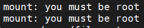
需要将rootfs目录所有者设置为root.
2.3.2 SD启动bootargs
setenv bootargs 'console=ttyPS0,115200 earlyprintk root=/dev/mmcblk0p2 rw rootwait uio_pdrv_genirq.of_id=generic-uio'
2.3.3 eMMC启动bootargs
setenv bootargs 'console=ttyPS0,115200 earlyprintk root=/dev/mmcblk1p2 rw rootwait uio_pdrv_genirq.of_id=generic-uio'
3 QSPI Flash启动
3.1 petalinux配置
3.2 内核flash错误修改
内核启动时,出现以下错误:
m25p80 spi0.0: found w25q256, expected n25q512a
m25p80 spi0.0: failed to read ear reg
m25p80 spi0.0: w25q256 (32768 Kbytes)
第一行错误是因为,petaLinux默认设备树中的flash为n25q512a,修改系统设备树system-conf.dtsi为w25q256即可,如下图所示:
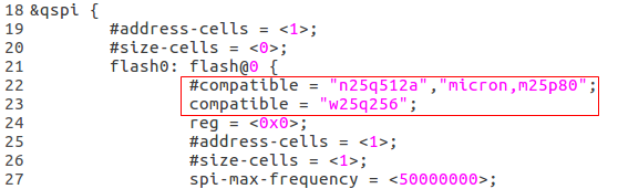
或者我们可以修改system-user.dtsi,修改后内容如下:
/include/ "system-conf.dtsi"
/ {
};

&flash0 {
	compatible = "w25q256";
};
第二行的错误是因为,Zynq QSPI flash 控制器只支持3字节的地址,因此只支持最大128Mbit的QSPI flash。 如果要支持更大的flash,需要使用QSPI flash中的bank寄存器。
而函数read_ear则正是为了读取bank/扩展地址寄存器,如下所示:
/**
 * read_ear - Get the extended/bank address register value
 * @nor:	Pointer to the flash control structure
 *
 * This routine reads the Extended/bank address register value
 *
 * Return:	Negative if error occured.
 */
static int read_ear(struct spi_nor *nor, struct flash_info *info)
{
	int ret;
	u8 val;
	u8 code;

	/* This is actually Spansion */
	if (JEDEC_MFR(info) == CFI_MFR_AMD)
		code = SPINOR_OP_BRRD;
	/* This is actually Micron */
	else if (JEDEC_MFR(info) == CFI_MFR_ST ||
		 JEDEC_MFR(info) == CFI_MFR_MACRONIX ||
		 JEDEC_MFR(info) == SNOR_MFR_ISSI)
		code = SPINOR_OP_RDEAR;
	else
		return -EINVAL;

	ret = nor->read_reg(nor, code, &val, 1);
	if (ret < 0)
		return ret;

	return val;
}
对应w25q256的数据手册如下:
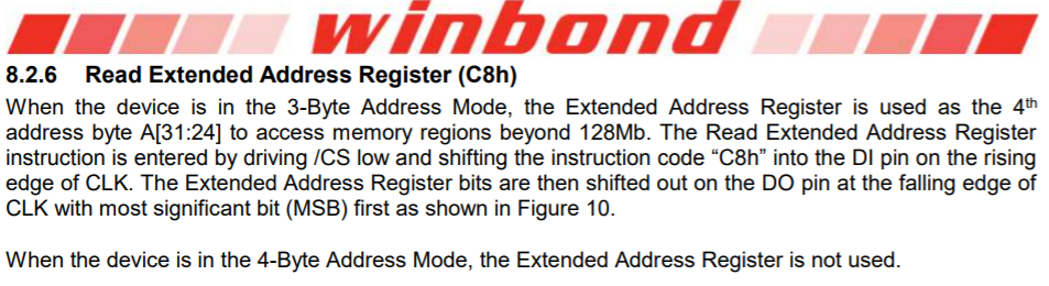
但是在read_ear函数中未对winbond进行支持,以至于其返回的值为-EINVAL,而winbond应该返回的值为SPINOR_OP_RDEAR(0xC8),故修改代码如下:
/* This is actually Spansion */
if (JEDEC_MFR(info) == CFI_MFR_AMD)
	code = SPINOR_OP_BRRD;
/* This is actually Micron */
else if (JEDEC_MFR(info) == CFI_MFR_ST ||
	 JEDEC_MFR(info) == CFI_MFR_MACRONIX ||
	 JEDEC_MFR(info) == CFI_MFR_ISSI ||
	 JEDEC_MFR(info) == SNOR_MFR_WINBOND)
	code = SPINOR_OP_RDEAR;
else
	return -EINVAL;
如此再对内核代码进行编译,则无上述错误提示。
4 UIO相关
4.1 linux的中断
4.1.1 GPIO编号
Zynq7020的GPIO包括:54个MIO和192个EMIO(64个输入和128个输出),其中MIO是PS这边的,而EMIO是PL这边的,不过EMIO内部和PS端相连,而MIO是能直接拉出到外部引脚上。
从UG585中可以看到,Zynq7020的GPIO分为了4组,其中BANK0和BANK1是MIO,共有54个,编号为0~53;BANK2和BANK3是EMIO,共有64个,编号为54 ~ 117。
进入到/sys/class/gpio目录下可以看到只有一个gpiochip906,代表它的第一个gpio是从906开始的,前面54个为MIO,如果要操作EMIO的第一个引脚,则文件描述符计算为:906+54=960。
4.1.2 Zynq7020的中断
4.1.2.1 中断总体结构
Zynq7020的GIC控制器结构如图所示:
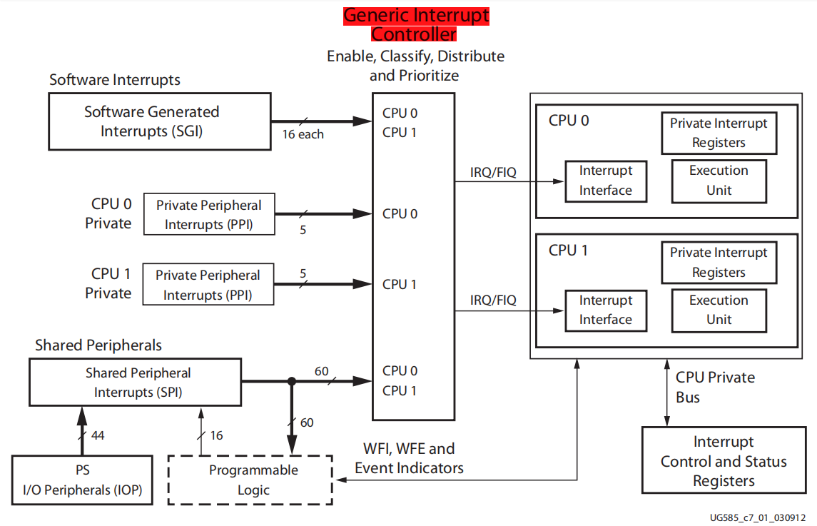
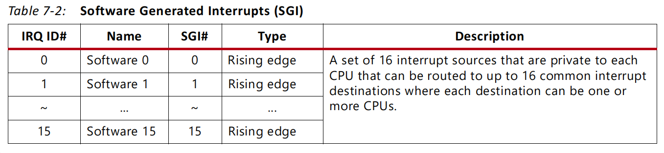
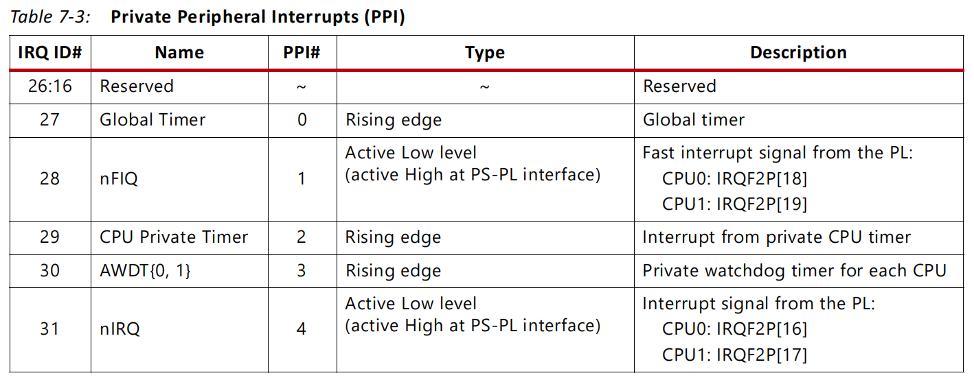
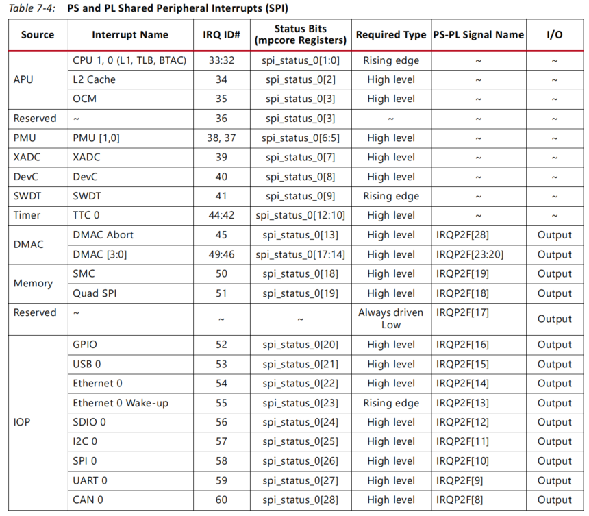
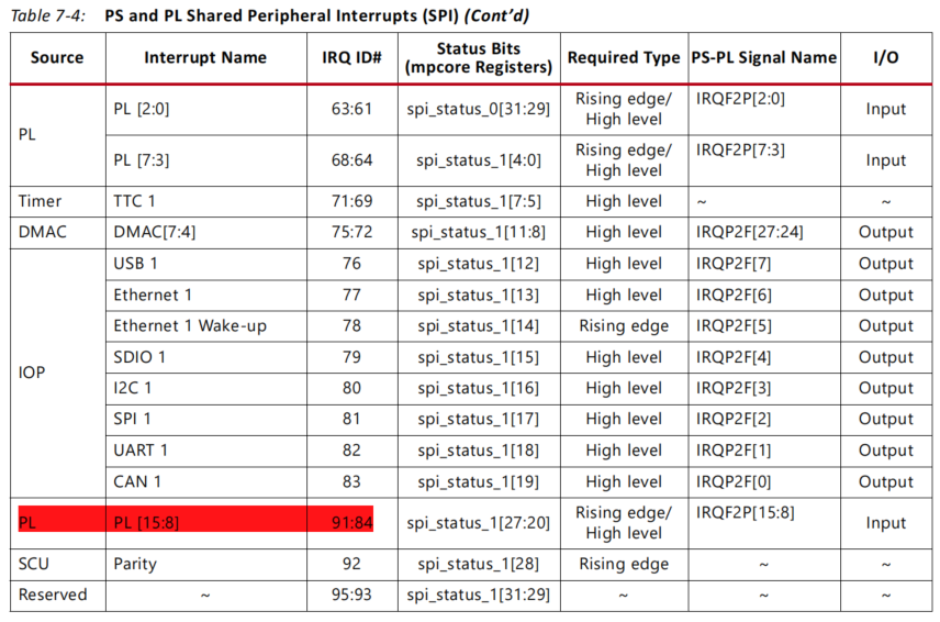
上图中间部分为GIC,也即中断控制器,用于对中断进行使能、关闭、掩码、设置优先等。Zynq中断大致可分为三个部分:SGI,软件生成的中断,共16个端口;PPI,CPU私有外设中断,有5个;SPI,共享外设中断,来自于44个PS端的IO外设以及16个PL端的中断。
具体中断 IRQ ID如下表所示:
4.1.2.2 设备树interrupts属性
在设备树⾥⾯,中断使⽤interrupts来描述。interrupts属性后⾯,会有不同的参数,一般是三个,有时是两个。
三个的时候:
第⼀个参数表⽰中断类型:0 则代表了SPI类型 ,1代表PPI类型
第⼆个参数表⽰:中断号,表示是第⼀个中断类型⾥⾯的第⼏个中断
第三个参数表⽰:中断触发方式:上升沿、下降沿、电平等
中断类型:
IPI:inter-processer interrupt 中断号0~15
PPI:per processor interrupts 中断号16~31
SPI:shared processor interrupts 中断号 32 ~32+224
SGI:software generated interrupts (SGI).
中断触发方式:
#define IRQ_TYPE_NONE 0
#define IRQ_TYPE_EDGE_RISING 1
#define IRQ_TYPE_EDGE_FALLING 2
#define IRQ_TYPE_EDGE_BOTH (IRQ_TYPE_EDGE_FALLING | IRQ_TYPE_EDGE_RISING)
#define IRQ_TYPE_LEVEL_HIGH 4
#define IRQ_TYPE_LEVEL_LOW 8
实例如下:
gpio0: gpio@e000a000 {
	compatible = "xlnx,zynq-gpio-1.0";
	#gpio-cells = <2>;
	clocks = <&clkc 42>;
	gpio-controller;
	interrupt-controller;
	#interrupt-cells = <2>;
	interrupt-parent = <&intc>;
	interrupts = <0 20 4>;
	reg = <0xe000a000 0x1000>;
};
interrupt-controller;是一个没有值的属性,用以表明这个节点描述的是一个中断控制器。
#interrupt-cells = <2>;表示:该节点的所有子节点的interrupts属性含两个参数。
interrupts = <0 20 4>;表示:中断类型为SPI;中断号为SPI里面的第20个(SPI中断号从32开始,故该中断号为32+20=52);中断触发方式为高电平触发。
两个的时候⼀般是这样出现:
touchscreen@0 {
	interrupt-parent = <&gpio0>;
	interrupts = <10 4>; /* MIO10, level high */
};
上述表示:中断控制器是gpio0;使⽤中断控制器gpio0的10号中断(这⾥的10号,对应MIO10号引脚);4是指触发的⽅式为高电平触发。
另外ZynqMP和Zynq的一个区别需要注意,ZynqMP的interrupt-parent指向的是&gic, 而Zynq指向了&intc。其实可以再看看其他的dtsi文件,可以发现,intc其实也是指向了CPU的gic,所以说实际上是一样的,并没有使用PL侧的INTC IP核中断。
UIO机制中虽然包含四种中断方式(高电平、低电平、上升沿、下降沿),但在zynq中只支持2种(高电平、上升沿)。
4.1.2.3 Zynq7020 MIO/EMIO中断号列表
| 引脚号 | 全局中断号 | 设备树中断号 | 备注 | 实例 |
|---|---|---|---|---|
| MIO0~53 | 共用gpio0中断号:52 | 0~53 | 中断控制器为gpio0 | MIO10中断配置:interrupt-parent = <&gpio0>;interrupts = <10 4>; |
| EMIO0~7 | 61~68 | 29~36 | 中断控制器为intc,ZynqMP为gic,中断类型为0:SPI,实际中断号需减去SPI中断偏移32 | EMIO3中断配置:interrupt-parent = <&intc>;interrupts = <0 32 4>; |
| EMIO8~15 | 84~91 | 52~59 | 中断控制器为intc,ZynqMP为gic,中断类型为0:SPI,实际中断号需减去SPI中断偏移32 | EMIO9中断配置:interrupt-parent = <&intc>;interrupts = <0 53 4>; |
4.2 坑人的问题
原计划PS端与PL端利用UIO进行交互,利用UIO实现内存的访问和中断的获取,设备树配置如下:
reserved-memory {
	#address-cells = <1>;
	#size-cells = <1>;
	ranges;

	reserved: buffer@0x10000000 {
	    //no-map;
	    reg = <0x10000000 0x200000>;
	};
};

shared-ddr {
	compatible = "generic-uio";
	linux,uio-name = "ps-pl-ddr";
	reg = <0x10000000 0x200000>;
};

pl2ps-irq0 {
	compatible = "generic-uio";
	status = "okay";
	interrupt-controller;
	interrupt-parent = <&gpio0>;
	interrupts = <11 3>;//MIO11
};

pl2ps-irq1 {
	compatible = "generic-uio";
	status = "okay";
	interrupt-controller;
	interrupt-parent = <&gpio0>;
	interrupts = <12 3>;//MIO12
};
上述设备树中,内存的读写已经实现。UIO中断通过MIO上的按键去模拟,但是中断始终无法触发!!!!遍访google,百度,yandex!!!花了整整10天时间,未能解决!!追踪过内核代码,各种修改设备树,均已失败告终!!按键都快按坏。
尝试通过devmem去写寄存器控制MIO,但是发现devmem无法操作MIO的寄存器,再次百度得知:“由于新内核中启用了电源管理机制,内核默认将设备处于暂停状态,从而使用devmem读写寄存器失败,关闭电源管理机制后能解决该问题”。参考链接如下:https://blog.csdn.net/zhaoxinfan/article/details/94048340
将下面图中红框的选项取消:
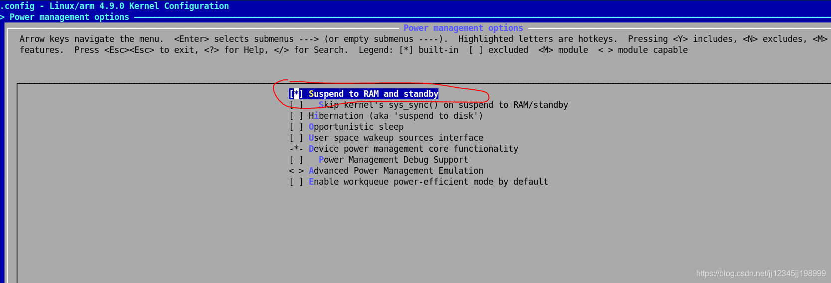
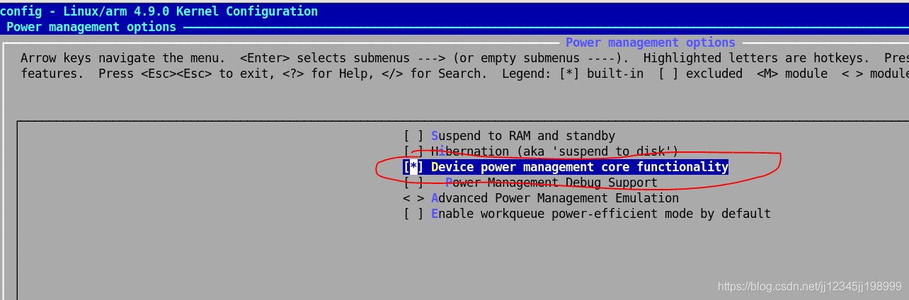
然后重新编译内核,烧写。
发现此时devmem已能够读写寄存器!同时UIO中断已经能够触发了!
5 设备挂载initramfs根文件系统
5.1 内核的配置
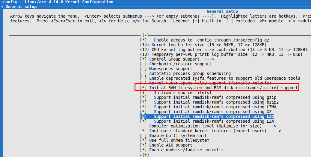
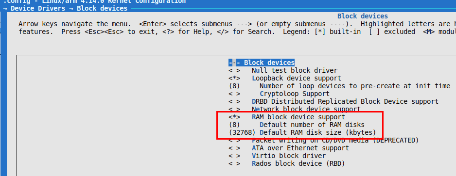
第三张截图中 Default number of RAM disks 一般设置为8,最小设置为1;Default RAM disk size设置为ramdisk镜像的大小,此处设置为32M,若要增加ramdisk镜像的空间,此处要对应修改。
5.2 ramdisk镜像的制作
#!/bin/sh

[ -f ramdisk.gz ] && rm ramdisk.gz
[ -f ramdisk.gz_test ] && rm ramdisk.gz_test
[ -f uramdisk.img.gz ] && rm uramdisk.img.gz

sudo dd if=/dev/zero of=ramdisk bs=1024 count=32768
sudo mke2fs -F -m0 ramdisk #格式化,-F强制,-m0不为管理员预留空间
sudo mount -t ext2 ramdisk ramfs
cd ramfs
sudo cp /home/bear/nfsroot/rootfs/* ./ -afR
cd -
sudo umount ramfs
gzip -v9 ramdisk   #生成ramdisk.gz

mkimage -n 'Ramdisk Image'  -A arm -O linux -T ramdisk -C gzip -d ramdisk.gz ramdisk.gz_test

cp ramdisk.gz_test  uramdisk.image.gz

mv uramdisk.image.gz /home/bear/tftpboot/
5.3 uboot启动参数配置
5.3.1 bootargs设置为initramfs启动
setenv bootargs 'console=ttyPS0,115200 earlyprintk root=/dev/ram0 rw rootwait uio_pdrv_genirq.of_id=generic-uio'
5.3.2 boot命令
5.3.2.1 网络启动内核及initramfs
setenv serverip 192.168.8.139
setenv ipaddr 192.168.8.168
setenv kernel_load_address 0x2080000
setenv devicetree_load_address 0x2000000
setenv ramdisk_load_address 0x4000000
setenv kernel_image zImage
setenv devicetree_image system.dtb
setenv ramdisk_image uramdisk.image.gz
setenv netboot_ramfs 'tftpboot ${kernel_load_address} ${kernel_image} && tftpboot ${devicetree_load_address} ${devicetree_image} && tftpboot ${ramdisk_load_address} ${ramdisk_image} && bootz ${kernel_load_address} ${ramdisk_load_address} ${devicetree_load_address}'
5.3.2.2 emmc启动
setenv emmcboot_ramfs 'if mmc dev 1 && mmcinfo; then run uenvboot; echo Copying Linux from eMMC to RAM... && load mmc 1 ${kernel_load_address} ${kernel_image} && load mmc 1 ${devicetree_load_address} ${devicetree_image} && load mmc 1 ${ramdisk_load_address} ${ramdisk_image} && bootz ${kernel_load_address} ${ramdisk_load_address} ${devicetree_load_address}; fi'
5.4 linux烧写PL bit流文件
5.4.1 bit流bin文件制作
5.4.1.1 bit_bin.bif文件
all:
{
        system.bit
}
5.4.1.2 生成system.bit.bin
bootgen -image $ROOT_PATH/proj/bit_bin.bif -arch zynq -process_bitstream bin
5.4.2 烧写脚本
mkdir -p /lib/firmware
cd /lib/firmware/
cp /run/media/mmcblk1p1/system.bit.bin .
echo system.bit.bin > /sys/class/fpga_manager/fpga0/firmware
6 内核崩溃分析
6.1 core 文件产生
6.1.1 方式1
设置系统最大产生20480(kB)的core文件,默认值为0,表示未开启
ulimit -c 20480
事实上,上述命令写在开机启动脚本中并未生效,故采用方式2。
6.1.2 方式2
修改/etc/security/limits.conf文件
#<domain>      <type>  <item>         <value>
#

*               soft    core            20480
#*               hard    rss             10000
#@student        hard    nproc           20
#@faculty        soft    nproc           20
#@faculty        hard    nproc           50
#ftp             hard    nproc           0
#@student        -       maxlogins       4
6.1.3 core文件设置路径和名称
echo "/home/root/.lidar/core-%e-%p-%t" > /proc/sys/kernel/core_pattern
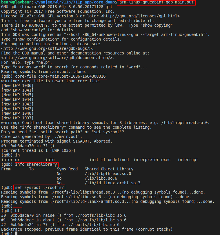
6.2 core文件分析
6.3 参考链接
https://blog.csdn.net/luronggui/article/details/118111897
https://jason--liu.github.io/2018/01/23/gdbdebug/
https://blog.csdn.net/u014213012/article/details/111593778

 浙公网安备 33010602011771号