how to generate an analog output from a in-built pwm of Atmega 32AVR microcontrloller?
how to generate an analog output
from a in-built pwm of Atmega 32AVR microcontrloller?
you need a resistor, a capacitor and an opamp.
opamp is not really necessary when you are driving a mosfet, but will make life a bit easier.
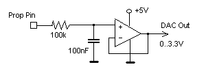
just be aware, that this dac will be quite noisy or/and slow.
The bigger cap/resistor values, quiter and slower the output.
another thing to be aware is that you better use 16bit pwm, as 8 bit pwm will give you only 256 discrete values -
that could be enough or too coarse, depends on your application, of course.
just google "PWM DAC" for more info and calculations.
one more thing - you could put several resistor/capacitor stages in series to improve on the noise side:
Create a Low-Pass RC filter that will filter out the frequency of your PWM.
The cutoff frequency should be at least 10 times lower than the frequency of your PWM.
A lower cutoff frequency will reduce the voltage ripple in the output signal.
Cutoff frequency is determined by:
f = 1/(2πRC)
Further reading:
Arduino’s AnalogWrite – Converting PWM to a Voltage
When I first started working with the Arduino platform (it was also my first experience with microcontrollers),
I was a little surprised that analogWrite didn’t actually output a voltage, but a PWM (pulse-width modulated) signal.
After all, the ATmega had a A-D (analog to digital) converter along with Arduino’sanalogRead.
The complementaryanalogWrite function was there, but no D-A (digital to analog) converter on the AVR chip itself.
Fortunately, there is an easy way to convert a PWM signal to an analog voltage.
To do so you only need to implement a simple single-pole low pass filter. Does it sound complicated?
It isn’t. There are some great online tools to help.
Once you learn how to make one, you can quickly and easily output analog voltages from not only the Arduino,
but PICs as well as any other microcontroller that has PWM output.
PWM Primer
Pulse width modulation (or PWM as it is most commonly known), is a way of encoding a voltage onto a fixed frequency carrier wave.
Commonly used for radio controlled devices, it is similar to FM (frequency modulation) or AM (amplitude modulation) in what it accomplishes.
Each type of modulation scheme has its own advantages and disadvantages.
AM modulation was the first type of modulation used for radio transmissions.
It is the most simple modulation scheme to implement, requiring only a single transistor or vacuum tube amplifier as was done in the early days of radio.
However, it suffers from excessive noise and therefore, FM modulation was invented.
In this modulation technique, the voltage signal is no longer related to the strength of the signal.
That is why FM radio has superior noise and fidelity qualities over AM radio, though it is not as simple to implement in circuitry.
With the need for digital communication, a new modulation technique was invented – PWM.
This technique shares the same noise immunity as FM, to which it is very similar.
The biggest difference is the simplicity and digital nature of the modulation.
Instead of varying the modulation frequency with voltage, an output is merely switched on and off at a fixed frequency.
The percentage of the on-time is in proportion to the signal voltage.
To see better what this means, let’s examine what a PWM signal looks like for various levels.
In the following image, the duty cycle is the output value from the PWM pin of an Arduino divided by 255:
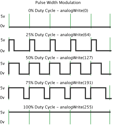
PWM outputs (curtesy arduino.cc)
For the Arduino, you write a value from 0 to 255 on a PWM pin, and the Arduino library will cause the pin
to output a PWM signal whose on time is in proportion to the value written.
When it comes time for us to actually write an output voltage, the 0-255 value lacks meaning.
What we want is many cases is a voltage. For our purposes, we will assume the Arduino is running at Vcc = 5 volts.
In that case, a value of 255 will also be 5 volts.
We can then easily convert the desired voltage to the digital value needed using simple division.
We first divide the voltage we want by the 5 volts maximum. That gives us the percentage of our PWM signal.
We then multiply this percentage by 255 to give us our pin value. Here is the formula:
Pin Value (0-255) = 255 * (AnalogVolts / 5);
Modulating a Signal
In addition to just setting the output voltage, you may need to actually modulate a signal.
To modulate a signal, we simply call analogWrite with the value corresponding to our signal voltage.
One way to do this would be to read the voltage at an analog pin, and then write it back out.
For example:
int pwmPin = 9; // output pin supporting PWM
int inPin = 3; // voltage connected to analog pin 3, e.g. a potentiometer
int val = 0; // variable to store the read value
float volt = 0; // variable to hold the voltage read
void setup()
{
pinMode(pwmPin, OUTPUT); // sets the pin as output
}
void loop()
{
val = analogRead(inPin); // read the input pin
volt =(5.0 * val) / 1023;
val = 255 * (volt / 5);
analogWrite(pwmPin, val);
}
Now in this example, we obviously won’t be need to convert our output voltage back to a voltage, but will instead transmit our modulated signal as it is. If you have an oscilloscope, you can attach it to the output, and a potentiometer to the input and watch your PWM signal change with the input value. There are many applications for PWM modulation, the most commonly being control of servos – either directly by wire or by radio-control. The Arduino has a nice library that handles creating the correct PWM signal for servos. For more information, see theArduino Servo Library.
Changing the Modulation Frequency
Most microprocessors permit you to change the modulation frequency for PWM pins. The Arduino has its own set default values. For pins 3,9,10,11 it is approximately 488 Hz. For pins 5 and 6, it is about 977 Hz. These values are for a stock Arduino running at 16MHz. You can change these frequencies easily by writing new values to the appropriate timer register. For example, to change the frequency of timer 2, which controls pins 9 and 10, to 3,906 Hz, you would set its register like so:
TCCR1B = TCCR1B & 0b11111000 | 0x02;
On the Arduino website, there is a nice tutorial on setting timer frequencies and their ramifications.
Low Pass Filtering
Now that you understand how PWM works and can even change the frequency, it is time to take a look at how to implement a simple low pass filter. This simple piece of circuitry will convert your PWM output into a voltage corresponding to the percentage of the PWM waveform. You will then have a complete D-A converter for your Arduino or other microcontroller.

If we examine the circuit on the left, when a voltage is applied to the input of R, the capacitor C will begin to charge. When it is charged, it will cease to conduct current and the voltage at the output of this circuit will match the input (assuming a high impedance load). If you remember that capacitors block DC currents, but pass AC currents, you can see that any DC voltage input will also be output, but high frequency AC voltages will be shorted to ground. For anything in between, i.e. lower frequency AC voltages, they will be filtered according to the R/C time constant formed by the resistor-capacitor network.
While this circuit is very simple, choosing the appropriate values for R & C encompass some design decisions – namely, how much ripple can we tolerate and how fast does the filter need to respond? These two parameters are mutually exclusive. In most filters, we would like to have the perfect filter – one that passes all frequencies below the cutoff frequency, with no voltage ripple. While no such ideal filter exists, we can achieve close to it by using a multiple pole filter. Such a filter would incorporate many components in a ladder configuration. While such a filter has wonderful performance characteristics, its complexity and cost is unnecessary for simple D-A conversion.
In such cases, we only need a simple single pole filter as shown above. We can achieve a reasonable voltage ripple for a single price – a low cutoff frequency. A low cutoff frequency has two ramifications. First, it limits the speed by which we can vary our output voltage. Second, there is a response delay when changing the voltage until the steady-state voltage is reached. For many of the more common applications, this trade-off is perfectly acceptable. Let’s now look at an example.
First, let’s choose our maximum ripple voltage. When we filter this high frequency PWM signal, a small component of it will always make it through the filter. That happens because our capacitor is too small to filter it out entirely. We could choose a very large capacitor /resistor combination that would get a very high proportion of it, but then it would take a long time to reach the proper output voltage as the capacitor charges. That would greatly limit how fast our signal can change and be seen at the output. Therefore, we need to choose a reasonable value for the ripple voltage. A popular application would be to change the voltage of a MOSFET. Since MOSFETs are voltage controlled devices, we can easily drive them with our microcontroller with PWM and a low-pass filter. Any ripple voltage present at the input would also be present at the output. For this example, assume the MOSFET will be driving a non-critical load such as a high power LED. In this instance, we merely need to stay within reasonable limits so the peak current in the LED will not be exceeded. In this case a 0.1 volt ripple would be more than adequate.
Next we choose a capacitor value. While it would seem the next step would be choosing a cutoff frequency (and it normally would be), there are additional considerations such as output load and capacitor cost. If we were only driving the gate of a MOSFET, there would be no output load to speak of. In such case, we could choose a cheap ceramic cap such as 0.1uF and then choose the resistor we need to achieve the cutoff frequency desired. If, on the other hand, we need some current from our output, then we will need a smaller resistor and a correspondingly larger capacitor. For a recent circuit, I found I needed a 2.2uF capacitor to prevent my modest load from altering the output voltage too significantly. Designing this circuit for non-trivial loads is beyond the scope of this article. If you find yourself in such a need, the best approach would be to start with at least a 1uF capacitor and then test how your output voltage changes with load. Increase your capacitor until the load has a low enough effect to be acceptable. Another way to look at this circuit would be to think of it as a poorly regulated power supply. It only meant to convert digital signals to an output voltage; not to drive a load as well. Buffer the output with an op-amp or a FET first. Then drive your load.
For our example, let’s choose a capacitor value of 1.0uF. For driving a MOSFET, you can use something even smaller, but this size will let us have a small load. Next, we need to choose a cutoff frequency or response time. These two parameters are related but not the same. For simple things like driving LEDs, we are more concerned with a response time. Our response time can be pretty generous. Let’s choose a settling time (to reach 90% of the final value) of 0.1 seconds, which would require a resistor of 15K ohms.
You may be wondering how to calculate these values, or others of your own. Rather than delve into a lot of equations, I have found something better.
This excellent online calculator does all the hard math for you, calculating cutoff frequency, response times, voltage ripple and other values.
It even draws a transient analysis graph for you – displaying your ripple and how the voltage ramps up over time. Here is the output graph for this example:

Conclusion
You are now armed with the knowledge you need for creating and using your own digital to analog circuit. Such circuits are incredibly useful. My favorite is driving MOSFETs and op-amps. By sampling a current or voltage somewhere, you can then determine what voltage you need to output to create the level of current or voltage you need. By means of such a simple system, you can make your own voltage regulators, current regulators, LED drivers, etc. The possibilities are endless.
If you have any questions about this article, please drop me a note in the comments. If you have any improvements, corrections or additions, please let me hear about them as well.

 浙公网安备 33010602011771号