One-wire Demo on the STM32F4 Discovery Board
One-wire Demo on the STM32F4 Discovery Board
The 1-wire protocol
The Dallas (now Maxim) 1-wire protocol uses a ground wire and a single wire that is both Vdd and data. This data line is treated by the master and slave devices as an open-collector line. By convention, master and slave let the line float high, but pull the line low to alert the other device or to drive data on the line. The data line must include a 4.7 kohm resistor to +5 VDC, so the data line idles at a logic high. Note that there are conditions where you might want to switch in a stronger pullup temporarily; if your device requires such a stronger pullup, it will be called out in the datasheet.
The protocol requires that both master and slave follow a prescribed sequence of operations and adhere to timing constraints. Full details on protocol and timing can be found in any of the Maxim/Dallas data sheets for the 1-wire devices.
The master must drive the data line in open-drain mode; the master CANNOT have internal pullups or pulldowns activated!
Interactions between master and slave (device) always begin with the master pulling the data line low for at least 480 usecs; this is called a reset or initialization pulse. The master releases the data line so the pullup resistor can pull the line high. The device must then respond by pulling the data line low for 60 to 240 usecs; this is called a presence pulse. After sending the presence pulse, the device releases the data line so it can return high.
After the master sees the presence pulse, the master is free to send a command byte to the device. Details at this point vary based on the number and type of devices connected. I don't want to get bogged down in the details of multi-drop 1-wire networks, so I'll refer you to the Maxim literature. For this demo, I'm going to focus on a single 1-wire device hooked to the master.
The demo setup
I had a DS1820 temperature sensor in my junk box, so that is the device I used. The DS1820 datasheet on the Maxim website contains all the timing and handshaking info you need to get the device talking to your micro.
For the "micro", I chose to use an STMicros STM32F4 Discovery board. Yes, it is overkill, but it's cheap, kind of hobbyist friendly, and I had one laying around.
I chose to use port pin PC1 for my 1-wire data line. I tied a 3.9 kohm resistor between +5 VDC on the Disco board and PC1. I then connected up a DS1820 by wiring its GND pin to GND on the Disco board, its Vdd pin to +5 VDC on the Disco board, and its DQ (data) line to PC1.
Finally, I brought out PD8 and PD9 from the Disco board to an RS-232 level shifter, so I could use TeraTerm to check the results of my program.
The code
The code for making all of this work with the DS1820 is pretty straightforward. I've added support for features such as reading the device's ROM, which contains the family code and serial number, as well as the scratchpad. The scratchpad is a nine-byte block of RAM that contains the latest conversion information as well as some alarm information.
Sending 1s and 0s from the master in the 1-wire protocol is simple. The master marks the start of a bit by pulling the data line low. If the bit to send is a 1, the master pulls the data line high between 1 and 15 usecs later. If the bit to send is a 0, the master keeps the data line low. Between 60 and 120 usecs after the start of the bit, the master must ensure the data line is again pulled high. This marks the end of the bit time. Obviously, if the master just sent a 1, the line is already high at the end of this bit time.
This operation is performed a total of eight times to send a single byte. Note that bytes are sent LSB first.
Reading 1s and 0s from the slave is very similar. Again, the master marks the start of a bit by pulling the data line low. The master waits about 15 usecs, then releases the line and changes the data line to an input. About 15 usecs later, the master reads the state of the data line; a high means the slave sent a 1, and a low means the slave sent a 0. The master waits an additional 35 usecs or so before repeating the process for the next bit, if needed.
Again, this operation is performed a total of eight times to read a single byte. As before, bytes are sent LSB first.
Commands from the master to the slave follow a set sequence:
- Send the initialization pulse
- Send a command that selects a particular device or all devices on the network
- Send a command plus data OR receive data from the device
- (Optionally) Read data from the device
- Send the initialization pulse
- Send a SKIP_ROM command
- Send a CONVERT_TEMP command
To read the data from this conversion, I need to read the scratchpad, then pull the data from bytes 0 and 1. This uses the following steps:
- Send the initialization pulse
- Send a SKIP_ROM command
- Send a READ_SCRATCHPAD command
- Read nine bytes of data from the device
Once I have the scratchpad with the temperature data, I simply use the values in bytes 0 and 1 to compute the temperature.
Here is the code for setting up the GPIO pin I've selected:
/*
* Specify the port and pin used for 1-wire comms
*/
#define ONEWIRE_PIN_NUM 1
#define ONEWIRE_PIN_MASK (1<<ONEWIRE_PIN_NUM)
#define ONEWIRE_PORT GPIOC
#define ONEWIRE_CLK RCC_AHB1Periph_GPIOC
/*
* OneWire_Init hardware-specific configuration of 1-wire I/O
*/
static void OneWire_Init(void)
{
GPIO_InitTypeDef GPIO_InitStructure;
RCC_AHB1PeriphClockCmd(ONEWIRE_CLK, ENABLE); // route the clocks
GPIO_InitStructure.GPIO_Pin = ONEWIRE_PIN_MASK; // select the pin to modify
GPIO_InitStructure.GPIO_Mode = GPIO_Mode_OUT; // set the mode to output
GPIO_InitStructure.GPIO_Speed = GPIO_Speed_100MHz; // set the I/O speed to 100 MHz
GPIO_InitStructure.GPIO_OType = GPIO_OType_OD; // set the output type to open-drain
GPIO_InitStructure.GPIO_PuPd = GPIO_PuPd_NOPULL; // set the pull-up to none
GPIO_Init(ONEWIRE_PORT, &GPIO_InitStructure); // do the init
}
This design lets me define a port and pin by changing the macros at the top, without having to touch the code itself; less risk of changing all but one hard-coded operations that way.
Next, I need a set of macros for manipulating the registers associated with my 1-wire data pin. Here they are:
/*
* The following macros collapse direct accesses of the GPIO registers into
* single commands. Refer to stm32f4xx_gpio.c and the STM32F4xx Reference
* Manual (GPIO chapter) for details.
*/
#define ONEWIRE_INPUT_READ ONEWIRE_PORT->IDR&ONEWIRE_PIN_MASK
#define ONEWIRE_OUTPUT_HIGH ONEWIRE_PORT->BSRRL=ONEWIRE_PIN_MASK
#define ONEWIRE_OUTPUT_LOW ONEWIRE_PORT->BSRRH=ONEWIRE_PIN_MASK
#define ONEWIRE_CONFIG_OUTPUT ONEWIRE_PORT->MODER|=(GPIO_Mode_OUT<<(ONEWIRE_PIN_NUM*2))
#define ONEWIRE_CONFIG_INPUT ONEWIRE_PORT->MODER&=~(GPIO_MODER_MODER0<<(ONEWIRE_PIN_NUM*2))
These macros let me read from the pin when it's an input, set the pin high or low when it's an output, and configure the pin for either output or input operation.
Now let's look at what is involved in sending an initialization pulse:
static void SendInitialization(void)
{
ONEWIRE_OUTPUT_HIGH;
ONEWIRE_CONFIG_OUTPUT;
delay_usecs(500);
ONEWIRE_OUTPUT_LOW;
delay_usecs(500);
ONEWIRE_OUTPUT_HIGH;
ONEWIRE_CONFIG_INPUT;
delay_usecs(50);
}
The only interesting bit here is that whenever I switch the line from output to input, I need to make sure I first drive the output high. This is because the open-collector driver on the pin will clamp the line low otherwise, preventing the pin from being pulled up by the external resistor.
The function delay_usecs() does just what it says, delay a given number of microseconds. In my code, I used a spin-loop routine for the delay, but you can just as easily set up a timer for generating delays in hardware.
Next up is code for sending a byte. That is just a mix of sending 1s and 0s, based on the argument. Here is my routine:
static void SendByte(uint8_t val)
{
uint8_t n;
for (n=0; n<8; n++)
{
ONEWIRE_OUTPUT_LOW;
ONEWIRE_CONFIG_OUTPUT;
delay_usecs(5);
if (val & 1) ONEWIRE_OUTPUT_HIGH;
delay_usecs(95);
ONEWIRE_OUTPUT_HIGH;
delay_usecs(5);
val = val >> 1;
}
}
No rocket science here. Bring the line low to start a bit slot, wait 5 usecs, and check the bit to send. If sending a 1, drive the line high, else leave the line low. Wait the remaining 95 microseconds, then ensure the line is high. Rotate the byte to send, repeat until all bits are sent, done.
All that's left at the low level is reading a byte:
static uint8_t ReadByte(void)
{
uint8_t n;
uint8_t val;
val = 0;
for (n=0; n<8; n++)
{
val = val >> 1;
ONEWIRE_OUTPUT_LOW;
ONEWIRE_CONFIG_OUTPUT;
delay_usecs(15);
ONEWIRE_OUTPUT_HIGH;
ONEWIRE_CONFIG_INPUT;
delay_usecs(10);
if (ONEWIRE_INPUT_READ) val = val | 0x80;
delay_usecs(35);
}
return val;
}
In this case, the master needs to pull the line low to provide a bit slot, then wait a moment before releaseing the line. After another short delay, the master samples the data line. If the line is still low, the device is sending a 0. If the line is high, the device is sending a 1. Repeat for eight bits, you have a byte, and you're done.
With the low-level stuff out of the way, I just built up some simple functions for accessing the DS1820. Here is how to read the termperature after a termperature conversion command has completed:
static void ReportTemperature(void)
{
uint32_t val;
uint32_t t;
uint32_t frac;
uint8_t n;
SendInitialization();
delay_usecs(100);
SendByte(SKIP_ROM);
SendByte(READ_SCRATCHPAD);
for (n=0; n<9; n++)
{
pad[n] = ReadByte();
}
val = (pad[1] * 256 + pad[0]); // temp in 0.5 degs C
t = val;
val = val >> 1; // temp in degs C
frac = 0;
if ((val << 1) != t) frac = 5; // if the roll lost a bit, allow for 0.5 deg C
xprintf("\n\rTemperature is: %d.%d degrees C", val, frac);
}
This code builds the termperature from bytes 0 and 1 of the scratchpad. This value will be the termperature in 0.5 degC increments. My code rolls this value right one bit, then creates a fake floating-point value so the output looks correct. Note that you can use other values in the scratchpad to get finer resolution on the temperature value, if you like; consult the Maxim docs for details.
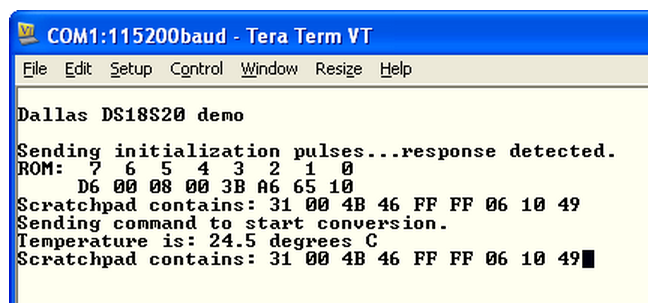
Here is a screenshot of my demo program as it appears in TeraTerm:
Here is a picture of my test setup:

As you can see, the 1-wire devices are easy to use and pretty forgiving.
I have built up networks of these devices spanning dozens of meters, run them down buried bore holes, and never had problems reading data. Communications can be a bit slow, since it takes many milliseconds to perform some of the operations, but if you don't need speed and want simple wiring, the 1-wire family rates a look.
Here is a zip of the source file for this code. Note that you will not be able to rebuild this code as-is, since it uses my custom STM32F4 libraries for UART comms and suchlike. However, I've included the binary image, if you want to add a DS1820 to your Disco board and try out my program.

 浙公网安备 33010602011771号