Software UART, Timer, PWM, External Interrupt
How can you add extra hardware UARTs to a 32bit
TMS470 ARM7-based microcontroller at zero cost?
Solution:
Designers can use the high-end timer (HET) peripheral found on all Texas Instruments ARM7-based,
32-bit TMS470 microcontrollers to implement additional, full-duplex high-speed UART interfaces
with interrupt capability and zero ARM7 CPU overhead.
The TMS470 HET peripheral is a complex, high-performance RISC coprocessor that operates independent of the main ARM7.
The HET can be used to implement complex, timed I/O operations, such as multiple UART interfaces.
Using a small piece of software, designers can implement hardware UART module-like functionality
with independent background transmission and reception.
Furthermore, interrupts are provided, allowing for an event-oriented application program flow.
A conceptual overview of the interaction of the different components is shown in Figure 1.
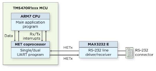
The HET operational principle lies in loop-oriented program execution.
The time for a loop to execute is referred to as a loop resolution (LR) clock cycle.
When the HET rolls over to the first instruction, it waits for the LR clock to restart program execution, ensuring synchronized timing.
The HET UART program processes the incoming and outgoing data streams bit by bit
using multiple LR cycles to achieve perfect hardware-generated timing.
For the transmission process, the ARM7 passes the data it wishes to transmit to the HET program.
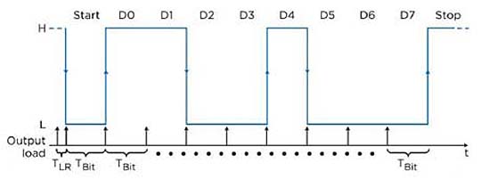
Figure 2 shows an example UART transmission.
Changes to the output signal line are required only at the end of each bit period.
These transitions are preloaded into the HET pin logic in advance of the next LR cycle
that matches the UART bit timing and become active at the beginning of the following LR cycle.
For the given example, a total of 10 transitions are needed and preloaded.
The entire UART data stream is output to an HET device's HET I/O pin in the background.
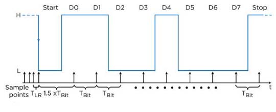
For the reception process, the incoming UART data stream delivered to an HET device I/O pin is decoded.
The operational principle is that the HET UART is polling the receive signal line
with a frequency higher than the baud rate until a zero logic level (start bit) is detected.
This is necessary because the incoming data is asynchronous to the HET timing.
The value of the first data bit is then determined 1.5 bit periods after the start bit was detected,
which is in the middle of its bit period. Then, all other bits are read one bit period spaced apart from each other.
For this process to work, a fine time resolution is needed to minimize the offset error introduced due to the start bit detection principle.
Figure 3 shows the time diagram of an example UART reception.
In this case, a total of nine samples are taken after the start bit high-to-low transition was detected.
Upon the reception of a full character, the ARM7 program is notified, which then can directly fetch the received data from the HET.
With the provided solution, it is possible, for example, to implement two additional full-duplex 115,200-baud UARTs
on a TMS470R1A256 device-yielding a total of four available UART modules.
About the author
Andreas Dannenberg is MSP430/TMS470 microcontroller applications engineer at Texas Instruments Inc.
Comments may be sent to dannenberg@ ti.com.
Soft UART on LPC13xx
For the ROV project I need two UART connections (one for RS485 to the onboard controller and one for receiving input from the VNC2 USB host controller).
And since the LPC1347 only has one UART I needed a soft UART for one of the connections.
Fortunately for me, NXP provides an implementation in AN10955.
AN10955: Full-duplex software UART for LPC111x and LPC13xx (v.1.0)
This application note illustrates how software running on an LPC111X or LPC13XX processor
can implement the behavior of a standard Universal Asynchronous Receiver/Transmitter (UART).
There was only one problem with it:
it doesn't work. Or rather, it works for a while and then stops receiving anything
(scoping the UART line confirmed that the VNC2 chip continued to send data so the problem had to be in the soft UART code).
Yea, intermittent errors – what's not to like… (Read on for the problem and the solution.)
How the soft UART works
In order to find out the problem I first had to figure out how the soft UART actually works.
Here's a brief recap – of the RX part only:
- One of the 32 bit timers is used to keep track of everything. I use
CT32B0. - The timer is configured to count from 0 to 0x3FFFFFFF after which it resets to 0 and continues.
No interrupt is generated when reset occurs and no prescaler is used. - Two values are pre-calculated: a "bit length" which is the number of cycles between each bit
(in my case: 72.000.000 clock cycles/sec and 9600 bits/secs yields 7500 timer ticks per bit
which is defined in theBIT_LENGTHmacro in the header file –
and the length for all nine bits (8 data bits and one stop bit) which is simply 9 * bit length
– defined in theSTOP_BIT_SAMPLEmacro. - The timer uses a capture pin to capture the value of the timer counter
when the RX signal switches from high to low or vice versa and
generate an interrupt when a transition occurs. I use CT32B0_CAP0 on pin PIO1.27. - Whenever a timer interrupt occurs the method
swu_isr_rx()
(and the TX counterpartswu_isr_tx()but we'll ignore that for now) is called.
This is where all the processing occurs. - Basically, the method measure PCLKs between signal transitions and use that to construct the received byte.
Also, when the first high-to-low event occurs, the timer'sMR1register is loaded with the timer value for
when the stop bit is expected (nine bit lengths from receiving the start bit).
The problem
The problem is in the code that calculates when the stop bit is expected. This is what it looks like:
edge_last = (signed long int) RX_ISR_TIMER->CR0; //initialize the last edge
  edge_sample = edge_last + (BIT_LENGTH >> 1); //initialize the sample edge
  if (edge_sample < edge_last) //adjust the sample edge...
    edge_sample |= ADJUST; //... if needed
  swu_bit = 0; //rx bit is 0 (a start bit)
  RX_ISR_TIMER->IR = 0x02; //clear MAT1 int flag
  edge_stop = edge_sample + STOP_BIT_SAMPLE; //estimate the end of the byte
  if (edge_stop < edge_last) //adjust the end of byte...
    edge_stop |= ADJUST; //... if needed
edge_last is the timer value when the start bit is received. edge_sample is half a bit length later. That is, in the middle of the bit instead of right at the start where the transition happens.edge_stop is calculated as STOP_BIT_SAMPLE PCLKs later (which is (9*BIT_LENGTH)).
Then it is checked if edge_stop has gotten so high that it has overflowed and is now less then the time of the start bit.
If that happens, ADJUST is added. Which is 0x40000000. Remember, the timer only counts up to 0x3FFFFFFF.
However! That last if-statement will never be true. And that is the bug!
If the timer counted the entire 32 bits it would work, but it doesn't – it only counts up to 0x3FFFFFFF.
And therefore the edge_stop will never wrap around and be less than edge_last.
But it can, however, become greater than 0x3FFFFFFF
(if, for example, the start bit is received when the timer is at 0x3FFFFDFF, in which case edge_stop would be set to 0x400105AB).
And the timer will never reach that value because it resets to zero when it reaches 0x3FFFFFFF.
So the "stop bit time reached – grab the byte and put it into the buffer" code will never run.
The solution
The solution is simple. What we really wanted to do in the last two lines of the code above was,
"If the calculated stop bit time is greater than the timer's maximum, wrap it around".
And that looks like this:
if( edge_stop >= ADJUST )   // Adjust the stop bit time if necessary
    edge_stop -= ADJUST;
And hey presto – everything works!
I also removed a couple of other if statements that would never come true (same reason as above).
/***********************************************************************
 * $Id:: i2c_example.c 1332 2008-11-19 21:20:07Z tangdz                $
 *
 * Project: LPC11XX/LPC13XX Software UART
 *
 * Description:
 *    This file contains the interface definition for the software
 *    UART example.
 *
 ***********************************************************************
 * Software that is described herein is for illustrative purposes only
 * which provides customers with programming information regarding the
 * products. This software is supplied "AS IS" without any warranties.
 * NXP Semiconductors assumes no responsibility or liability for the
 * use of the software, conveys no license or title under any patent,
 * copyright, or mask work right to the product. NXP Semiconductors
 * reserves the right to make changes in the software without
 * notification. NXP Semiconductors also make no representation or
 * warranty that such application will be suitable for the specified
 * use without further testing or modification.
 **********************************************************************/

#ifndef __SOFT_UART_H
#define __SOFT_UART_H

#include "LPC13xx.h"
#include "system_LPC13xx.h"
/*********************************************************
 ** Pin Definitions                                      **
 *********************************************************/
#define PORT_TX_PRO (3)   //P3.0
#define PORT_INT    (3)   //P3.1
#define PORT_INT_TX (3)   //P3.2
#define PORT_INT_RX (3)   //P3.3
#define PORT_CALL   (1)   //P1.11
#define PORT_SW_RX  (1)   //P1.5

#define PIN_TX_PRO  (0)
#define PIN_INT     (1)
#define PIN_INT_TX  (2)
#define PIN_INT_RX  (3)
#define PIN_CALL    (11)
#define PIN_SW_RX   (5)

/*********************************************************
 ** Software UART configurable parameters                **
 *********************************************************/
#define TEST_TIMER_NUM  0   /* 0 or 1 for 32-bit timers only */
#define TXBUFF_LEN      16
#define RXBUFF_LEN      16

//12000000/9600 = 1250 PCLKs
//PCLK=12MHz:
//#define BIT_LENGTH  1250

//24000000/9600 = 2500 PCLKs
//PCLK=12MHz:
//#define BIT_LENGTH  2500

//72000000/9600 = 7500 PCLKs
//PCLK=12MHz:
#define BIT_LENGTH  7500

#define STOP_BIT_SAMPLE (9*BIT_LENGTH)
/*********************************************************
 ** Exported Functions                                   **
 *********************************************************/
void swu_init( LPC_TMR_TypeDef* const UART_TIMER ); //Initialization and startup
void swu_tx_str( unsigned char const* );              //Transmit a string
void swu_tx_chr( const unsigned char );            //Transmit a single character
unsigned char swu_rx_chr( void );              //Read last character received

void swu_isr_tx( LPC_TMR_TypeDef* const TX_ISR_TIMER ); //Transmit interrupt routine
void swu_isr_rx( LPC_TMR_TypeDef* const RX_ISR_TIMER ); //Receive interrupt routine
extern void swu_rx_callback( void );   //Call back from true RX ISR (swu_isr_rx)

#endif//__SOFT_UART_H

/***********************************************************************
 * $Id::                                                               $
 *
 * Project: LPC11XX/LPC13XX Software UART
 *
 * Description:
 *   This software acts as a standard UART with 1 start, 8 data and 1
 *   stop bit (no parity) setup. TIMER32_0 MAT0.3 on P0.11 (pin 32
 *   on LQFP48 package) generates UART output while TIMER32_0
 *   CAP0.0 on P1.5 (pin 45 on LQFP48 package) receives serial data.
 *
 *   While P3.0 is low, a routine that calculates future transmission
 *   parameters is active. P3.1 is low while TIMER32_0 interrupt service
 *   routine (ISR) is running. P3.2 is low while software UART
 *   transmission portion of the TIMER32_0 ISR is executed. P3.3 indicates
 *   when the software UART receiving related TIMER32_0 ISR is active.
 *   P1.11 activity matches write access to the tx FIFO.
 *
 *   For this demo to run successfully pin P0.11(Soft TX) must be connected to
 *   P1.7(True TX) and pin P1.5(Soft RX) must be connected to P1.6(True RX).
 *   A PC or similar equipment capable of handling ASCII data at 9600 bit/s must be
 *   connected to the UART0 of the microcontroller. P1.7 and P1.6 are configured
 *   as GPIO pins and inactive mode (no pull-down/pull-up resistor enabled)
 *   in order not to influence the communication of soft uart.
 *
 *   UART0 of the LPC111x is not used in this demo. Regular U0Tx and U0Rx
 *   functionality is replaced by the software uart pins. UART0 pins are
 *   selected because most of the development boards already have needed
 *   hardware for voltage translation between the microcontroller and an
 *   external device.
 *   fosc = 12 MHz; PLL is used; System clock = AHB clock =48Mhz
 *
 ***********************************************************************
 * Software that is described herein is for illustrative purposes only
 * which provides customers with programming information regarding the
 * products. This software is supplied "AS IS" without any warranties.
 * NXP Semiconductors assumes no responsibility or liability for the
 * use of the software, conveys no license or title under any patent,
 * copyright, or mask work right to the product. NXP Semiconductors
 * reserves the right to make changes in the software without
 * notification. NXP Semiconductors also make no representation or
 * warranty that such application will be suitable for the specified
 * use without further testing or modification.
 **********************************************************************/

/*
 * Pin list:
 * P1.7:           [GPIO]  - needed because of a standard interface hw
 * P1.6:           [GPIO]  - needed because of a standard interface hw
 * P3.0:   TX_PRO  [GPO]   - next tx parameter processing (active low)
 * P3.1:   INT     [GPO]   - TIMER0 interrupt indicator (active low)
 * P3.2:   INT_TX  [GPO]   - swu tx interrupt indicator (active low)
 * P3.3:   INT_RX  [GPO]   - swu rx interrupt indicator (active low)
 * P1.11:  CALL    [GPO]   - tx UART routine call ind. (active low)
 * P0.11:  SWU_Tx  [MAT0.3]- software UART Tx pin
 * P1.5:   SWU_RX  [CAP0.0]- software UART Rx pin
 *
 *********************************************************/
#include "LPC13xx.h"  /* LPC13xx definitions */
#include "GPIO.h"
#include "LPC_SWU.h"

/*********************************************************
 ** Macro Definitions                                  **
 *********************************************************/
#define RX_OVERFLOW 4
#define RX_ACTIVE   2
#define TX_ACTIVE   1
#define ADJUST      (1<<30)
#define ALL1        0x000000FF

/*********************************************************
 ** Global Variables                                     **
 *********************************************************/
static volatile unsigned char cnt_edges; //no of char edges
static volatile unsigned char edge_index; //edge index for output
static volatile unsigned char swu_tx_st; //sw UART status
static volatile unsigned long int edge[ 11 ]; //array of edges
static volatile unsigned char last_edge_index, char_end_index; //last two events index
//software UART Tx related definitions
static volatile unsigned long int tx_fifo_wr_ind, tx_fifo_rd_ind;
static volatile signed long int swu_tx_cnt, swu_tx_trigger;
static volatile unsigned short int swu_tx_fifo[ TXBUFF_LEN ];
//software UART Rx related definitions
static volatile unsigned long int rx_fifo_wr_ind, rx_fifo_rd_ind;
static volatile signed long int swu_rx_cnt, swu_rx_trigger;
static volatile unsigned char swu_bit, cnt, cnt_bits, swu_rx_chr_fe;
static volatile unsigned long int swu_rbr, swu_rbr_mask;
static volatile signed long int edge_last, edge_sample, edge_current, edge_stop;
static volatile unsigned short int swu_rx_fifo[ RXBUFF_LEN ];
//definitions common for transmitting and receiving data
static volatile unsigned long int swu_status;

/*********************************************************
 ** Local Functions                                      **
 *********************************************************/
static void swu_setup_tx( void ); //tx param processing
__weak void swu_rx_callback( void );

/******************************************************************************
 ** Function name:   swu_setup_tx
 **
 ** Descriptions:
 **
 ** This routine prepares an array of toggle points that will be used to generate
 ** a waveform for the currently selected character in the software UART transmission
 ** FIFO; at the end this routine starts the transmission itself.
 **
 ** parameters:      None
 ** Returned value:  None
 **
 ******************************************************************************/
static void swu_setup_tx( void )
{
  unsigned char bit, i;
  unsigned long int ext_data, delta_edges, mask, reference;

  GPIOSetValue( PORT_TX_PRO, PIN_TX_PRO, 0 ); //indicate routine begin
  if ( tx_fifo_wr_ind != tx_fifo_rd_ind ) //data to send, proceed
  {
    swu_status |= TX_ACTIVE; //sw uart tx is active
    tx_fifo_rd_ind++; //update the tx fifo ...
    if ( tx_fifo_rd_ind == TXBUFF_LEN ) //read index...
      tx_fifo_rd_ind = 0; //...
    ext_data = (unsigned long int) swu_tx_fifo[ tx_fifo_rd_ind ]; //read the data
    ext_data = 0xFFFFFE00 | ( ext_data << 1 ); //prepare the pattern
    edge[ 0 ] = BIT_LENGTH; //at least 1 falling edge...
    cnt_edges = 1; //... because of the START bit
    bit = 1; //set the bit counter
    reference = 0x00000000; //init ref is 0 (start bit)
    mask = 1 << 1; //prepare the mask
    delta_edges = BIT_LENGTH; //next edge at least 1 bit away
    while ( bit != 10 )
    { //until all bits are examined
      if ( ( ext_data & mask ) == ( reference & mask ) )
      { //bit equal to the reference?
        delta_edges += BIT_LENGTH; //bits identical=>update length
      } //...
      else
      { //bits are not the same:
        edge[ cnt_edges ] = //store new...
          edge[ cnt_edges - 1 ] + delta_edges; //... edge data
        reference = ~reference; //update the reference
        delta_edges = BIT_LENGTH; //reset delta_ to 1 bit only
        cnt_edges++; //update the edges counter
      }
      mask = mask << 1; //update the mask
      bit++; //move on to the next bit
    }
    edge[ cnt_edges ] = //add the stop bit end...
      edge[ cnt_edges - 1 ] + delta_edges; //... to the list
    cnt_edges++; //update the number of edges
    last_edge_index = cnt_edges - 2; //calculate the last edge index
    char_end_index = cnt_edges - 1; //calc. the character end index

    edge_index = 0; //reset the edge index
    reference = LPC_TMR32B0->TC + BIT_LENGTH; //get the reference from TIMER0
    for ( i = 0; i != cnt_edges; i++ ) //recalculate toggle points...
      edge[ i ] = ( edge[ i ] + reference ) //... an adjust for the...
      & 0x3FFFFFFF; //... timer range
    LPC_TMR32B0->MR3 = edge[ 0 ]; //load MR3
    LPC_TMR32B0->MCR = LPC_TMR32B0->MCR | ( 1 << 9 ); //enable interrupt on MR3 match
    LPC_TMR32B0->EMR = LPC_TMR32B0->EMR | ( 3 << 10 ); //enable toggle on MR3 match
  }
  GPIOSetValue( PORT_TX_PRO, PIN_TX_PRO, 1 ); //indicate routine exit
  return; //return from the routine
}

/******************************************************************************
 ** Function name:   swu_tx_str
 **
 ** Descriptions:
 **
 ** This routine transfers a string of characters one by one into the
 ** software UART tx FIFO.
 **
 ** parameters:    string pointer
 ** Returned value:    None
 **
 ******************************************************************************/
void swu_tx_str( unsigned char const* ptr_out )
{
  while ( *ptr_out != 0x00 ) //read all chars...
  {
    swu_tx_chr( *ptr_out ); //...put the char in tx FIFO...
    ptr_out++; //...move to the next char...
  } //...
  return; //return from the routine
}

/******************************************************************************
 ** Function name:   swu_tx_chr
 **
 ** Descriptions:
 **
 ** This routine puts a single character into the software UART tx FIFO.
 **
 ** parameters:    char
 ** Returned value:    None
 **
 ******************************************************************************/
void swu_tx_chr( const unsigned char out_char )
{
  GPIOSetValue( PORT_CALL, PIN_CALL, 0 ); //IOCLR0  = pin_call;
  //write access to tx FIFO begin

  while ( swu_tx_cnt == TXBUFF_LEN )
    ; //wait if the tx FIFO is full
  tx_fifo_wr_ind++; //update the write pointer...
  if ( tx_fifo_wr_ind == TXBUFF_LEN ) //...
    tx_fifo_wr_ind = 0; //...
  swu_tx_fifo[ tx_fifo_wr_ind ] = out_char; //put the char into the FIFO
  swu_tx_cnt++; //update no.of chrs in the FIFO
  if ( ( swu_status & TX_ACTIVE ) == 0 )
    swu_setup_tx( ); //start tx if tx is not active

  GPIOSetValue( PORT_CALL, PIN_CALL, 1 ); //IOSET0  = pin_call;
  //write access to tx FIFO end
  return;//return from the routine
}

/******************************************************************************
 ** Function name:   swu_rx_chr
 **
 ** Descriptions:
 **
 ** This routine reads a single character from the software UART rx FIFO.
 ** If no new data is available, it returns the last one read;
 ** The framing error indicator is updated, too.
 **
 ** parameters:    None
 ** Returned value:    char
 **
 ******************************************************************************/
unsigned char swu_rx_chr( void )
{
  if ( swu_rx_cnt != 0 )
  { //update the rx indicator...
    rx_fifo_rd_ind++; //... if data are present...
    if ( rx_fifo_rd_ind == RXBUFF_LEN )
      rx_fifo_rd_ind = 0; //...
    swu_rx_cnt--; //...
  }
  if ( ( swu_rx_fifo[ rx_fifo_rd_ind ] & 0x0100 ) == 0 ) //update...
    swu_rx_chr_fe = 0; //... the framing error...
  else
    //... indicator...
    swu_rx_chr_fe = 1; //...
  swu_status &= ~RX_OVERFLOW; //clear the overfloe flag
  return ( (unsigned char) ( swu_rx_fifo[ rx_fifo_rd_ind ] & 0x00FF ) ); //return data
}

/******************************************************************************
 ** Function name: swu_isr_tx
 **
 ** Descriptions:
 **
 ** Handle timer output toggle events. If there are additional edge events
 ** in the edge[] array, continue to load the match register with them. If
 ** the last edge has been toggled, check for additional characters to load
 ** from FIFO, otherwise terminate transmission of characters.
 **
 ** parameters:  TX_ISR_TIMER pointer to timer resource to enable
 **              increased portability.
 ** Returned value:  None
 **
 ******************************************************************************/
void swu_isr_tx( LPC_TMR_TypeDef* const TX_ISR_TIMER )
{
  if ( 0 != ( TX_ISR_TIMER->IR & 0x08 ) )
  { //tx routine interrupt begin
    GPIOSetValue( PORT_INT_TX, PIN_INT_TX, 0 ); //tx interrupt activity begin

    TX_ISR_TIMER->IR = 0x08; //clear the MAT3 flag
    if ( edge_index == char_end_index ) //the end of the char:
    {
      TX_ISR_TIMER->MCR &= ~( 7 << 9 ); //MR3 impacts T0 ints no more
      swu_tx_cnt--; //update no.of chars in tx FIFO
      if ( tx_fifo_wr_ind != tx_fifo_rd_ind ) //if more data pending...
        swu_setup_tx( ); //... spin another transmission
      else
        swu_status &= ~TX_ACTIVE; //no data left=>turn off the tx
    }
    else
    {
      if ( edge_index == last_edge_index ) //is this the last toggle?
        TX_ISR_TIMER->EMR = 0x000003FF; //no more toggle on MAT3
      edge_index++; //update the edge index
      TX_ISR_TIMER->MR3 = edge[ edge_index ]; //prepare the next toggle event
    }

    GPIOSetValue( PORT_INT_TX, PIN_INT_TX, 1 ); //tx interrupt activity end
  }
}

/******************************************************************************
 ** Function name: swu_isr_rx
 **
 ** Descriptions:
 **
 ** Look for start bit falling edge. If found begin comparing edge events to
 ** decode the received character, followed by stop bit detection routine.
 **
 ** parameters:  TX_ISR_TIMER pointer to timer resource to enable
 **              increased portability.
 ** Returned value:  None
 **
 ******************************************************************************/
void swu_isr_rx( LPC_TMR_TypeDef* const RX_ISR_TIMER )
{
  signed long int edge_temp;
  //sw uart receive isr code begin
  if ( 0 != ( RX_ISR_TIMER->IR & 0x10 ) ) //capture interrupt occured:
  {
    GPIOSetDir( PORT_INT_RX, PIN_INT_RX, 0 ); //rx interrupt activity begin

    RX_ISR_TIMER->IR = 0x10; //edge dtcted=>clear CAP0 flag
    //change the targeted edge
    RX_ISR_TIMER->CCR = 0x0004 | ( 0x0003 - ( RX_ISR_TIMER->CCR & 0x0003 ) );
    if ( ( swu_status & RX_ACTIVE ) == 0 )
    { //sw UART not active (start):
      edge_last = (signed long int) RX_ISR_TIMER->CR0; //initialize the last edge
      edge_sample = edge_last + ( BIT_LENGTH >> 1 ); //initialize the sample edge
      if ( edge_sample < edge_last ) //adjust the sample edge...
        edge_sample |= ADJUST; //... if needed
      swu_bit = 0; //rx bit is 0 (a start bit)
      RX_ISR_TIMER->IR = 0x02; //clear MAT1 int flag
      edge_stop = edge_sample + STOP_BIT_SAMPLE; //estimate the end of the byte
      if ( edge_stop < edge_last ) //adjust the end of byte...
        edge_stop |= ADJUST; //... if needed
      RX_ISR_TIMER->MR1 = edge_stop; //set MR1 (stop bit center)
      RX_ISR_TIMER->MCR = RX_ISR_TIMER->MCR | ( 1 << 3 ); //int on MR1
      cnt = 9; //initialize the bit counter
      swu_status |= RX_ACTIVE; //update the swu status
      swu_rbr = 0x0000; //reset the sw rbr
      swu_rbr_mask = 0x0001; //initialize the mask
    }
    else
    {
      //reception in progress:
      edge_current = (signed long int) RX_ISR_TIMER->CR0; //initialize the current edge
      if ( edge_current < edge_last ) //adjust the current edge...
        edge_current |= ADJUST; //... if needed
      while ( edge_current > edge_sample )
      { //while sampling edge is within
        if ( cnt_bits != 0 )
        {
          if ( swu_bit != 0 ) //update data...
            swu_rbr |= swu_rbr_mask; //...
          swu_rbr_mask = swu_rbr_mask << 1; //update mask
        }
        cnt_bits++; //update the bit count
        edge_temp = edge_last + BIT_LENGTH; //estimate the last edge
        if ( edge_temp < edge_last ) //adjust...
          edge_last = edge_temp | ADJUST; //... the last edge...
        else
          //... if...
          edge_last = edge_temp; //... needed
        edge_temp = edge_sample + BIT_LENGTH; //estimate the sample edge
        if ( edge_temp < edge_sample ) //adjust...
          edge_sample = edge_temp | ADJUST; //... the sample edge...
        else
          //... if...
          edge_sample = edge_temp; //... needed
        cnt--; //update the no of rcved bits
      }
      swu_bit = 1 - swu_bit; //change the received bit
    }

    GPIOSetDir( PORT_INT_RX, PIN_INT_RX, 1 ); //rx interrupt activity end
  }

  if ( 0 != ( RX_ISR_TIMER->IR & 0x02 ) ) //stop bit timing matched:
  {
    GPIOSetDir( PORT_INT_RX, PIN_INT_RX, 0 ); //rx interrupt activity begin

    RX_ISR_TIMER->IR = 0x02; //clear MR1 flag
    if ( cnt != 0 )
    { //not all data bits received...
      swu_rbr = swu_rbr << cnt; //... make space for the rest...
      if ( swu_bit != 0 )
        swu_rbr += ALL1 << ( 8 - cnt ); //... add needed 1(s)...
    } //...
    swu_rbr &= 0x00FF; //extract data bits only
    if ( swu_bit == 0 ) //if the stop bit was 0 =>
      swu_rbr |= 0x00000100; //... framing error!
    swu_status &= ~RX_ACTIVE; //sw UART not active any more
    cnt_bits = 0; //reset the rx bit count
    if ( swu_rx_cnt != RXBUFF_LEN ) //store the rcved character...
    {
      swu_rx_cnt++; //... into the sw UART...
      rx_fifo_wr_ind++; //... rx FIFO
      if ( rx_fifo_wr_ind == RXBUFF_LEN )
        rx_fifo_wr_ind = 0; //...
      swu_rx_fifo[ rx_fifo_wr_ind ] = swu_rbr; //...
      if ( swu_rx_cnt >= swu_rx_trigger )
        swu_rx_callback( ); //rx 'isr' trig excded
    }
    else
    {
      swu_status |= RX_OVERFLOW; //rx FIFO full => overflow
    }
    RX_ISR_TIMER->MCR &= ~( 7 << 3 ); //MR0 impacts TIMER0 no more
    GPIOSetDir( PORT_INT_RX, PIN_INT_RX, 1 ); //IOSET0 = pin_intrx;     //rx interrupt activity end
  }
  //sw uart receive isr code end
}

/******************************************************************************
 ** Function name:   swu_init
 **
 ** Description:   Initialize variables used by software UART.
 **          Configure specific IO pins.
 **          Setup and start timer running.
 **
 ** parameters:    UART_TIMER  - pointer to timer resource to enable configuration.
 ** Returned value:  None
 **
 ******************************************************************************/
void swu_init( LPC_TMR_TypeDef* const UART_TIMER )
{
  //setup the software uart
  swu_tx_cnt = 0; //no data in the swu tx FIFO
  tx_fifo_wr_ind = 0; //last char written was on 0
  tx_fifo_rd_ind = 0; //last char updated was on 0
  swu_rx_trigger = 1; //>=1 char gnrts a rx interrupt
  swu_status = 0; //neither tx nor rx active

  /* Some of the I/O pins need to be clearfully planned if
   you use below module because JTAG and TIMER CAP/MAT pins are muxed. */
  LPC_SYSCON->SYSAHBCLKCTRL |= ( 1 << 9 );

  LPC_IOCON->PIO1_5 &= ~0x07; /*  Timer0_32 I/O config */
  LPC_IOCON->PIO1_5 |= 0x02; /* Timer0_32 CAP0 */
  LPC_IOCON->JTAG_TDI_PIO0_11 &= ~0x07;
  LPC_IOCON->JTAG_TDI_PIO0_11 |= 0x03; /* Timer0_32 MAT3 */

  //Timer0_32 setup
  UART_TIMER->TCR = 0x00; //stop TIMER0_32
  UART_TIMER->TCR = 0x02; //reset counter
  UART_TIMER->TCR = 0x00; //release the reset

  UART_TIMER->IR = 0x01F; //clear all TIMER0 flags
  UART_TIMER->PR = 0x00000000; //no prescaler
  UART_TIMER->MR0 = 0x3FFFFFFF; //TIMER0_32 counts 0 - 0x3FFFFFFF
  UART_TIMER->MCR = 2; //reset TIMER0_32 on MR0
  UART_TIMER->EMR = 0x0008; //drive MAT0.3 high
  UART_TIMER->TCR = 0x01; //let TIMER0_32 run
  NVIC_EnableIRQ( TIMER_32_0_IRQn ); //Enable the TIMER0_32 Interrupt

  while ( 0 == ( LPC_GPIO1->DATA & ( 1 << PIN_SW_RX ) ) )
    ; //wait for 1 on sw UART rx line
  UART_TIMER->IR = 0x10; //clear CAP0.0 flag
  UART_TIMER->CCR = 0x0006; //int on CAP0.0 falling edge

  cnt_bits = 0; //reset the rx bit count
}

/******************************************************************************
 ** Function name:   swu_rx_callback
 **
 ** Descriptions:  Default call-back function for handling RX character events.
 **          Runs in interrupt's context. If user doesn't overload, do
 **          nothing.
 **
 ** Parameters:    None
 ** Returned value:  None
 **
 ******************************************************************************/
#ifdef __ICCARM__
__weak void swu_rx_callback(void)
{
#elif __CODE_RED
  __attribute__ ((weak)) void swu_rx_callback(void)
  {
#endif
;
//do nothing if user doesn't overload
}
Timer-based AVR Software-UARTS
https://github.com/blalor/avr-softuart
Some AVRs do not have a hardware-UART others have one or two.
In case a UART is needed on "non-UART" AVRs or the available hardware-UARTS
are not enough to fullfill the project-needs a software-UART can be used.
The software-UART available here is based on the "gerneric software uart"
by Colin Gittins which can be downloaded from the iar.com website in the application-notes section.
I have ported/adapted this code to AVRs using avr-gcc/avr-libc and fixed some smaller mistakes.
This code does not need an external interrupt-pin for the RX-line - any input-pin will do.
But the RX pin gets sampled three times the baudrate so more process-time is needed compared
to an "external-int" approach as presented in various Atmel Application-Notes.
#if !defined(F_CPU)
#warning "F_CPU not defined in makefile - now defined in softuart.h"
#define F_CPU 3686400UL
#endif

#define SOFTUART_BAUD_RATE      2400

#if defined (__AVR_ATtiny25__) || defined (__AVR_ATtiny45__) || defined (__AVR_ATtiny85__)
#define SOFTUART_RXPIN   PINB
#define SOFTUART_RXDDR   DDRB
#define SOFTUART_RXBIT   PB0

#define SOFTUART_TXPORT  PORTB
#define SOFTUART_TXDDR   DDRB
#define SOFTUART_TXBIT   PB1

#define SOFTUART_T_COMP_LABEL      TIM0_COMPA_vect
#define SOFTUART_T_COMP_REG        OCR0A
#define SOFTUART_T_CONTR_REGA      TCCR0A
#define SOFTUART_T_CONTR_REGB      TCCR0B
#define SOFTUART_T_CNT_REG         TCNT0
#define SOFTUART_T_INTCTL_REG      TIMSK

#define SOFTUART_CMPINT_EN_MASK    (1 << OCIE0A)

#define SOFTUART_CTC_MASKA         (1 << WGM01)
#define SOFTUART_CTC_MASKB         (0)

/* "A timer interrupt must be set to interrupt at three times
 the required baud rate." */
#define SOFTUART_PRESCALE (8)
// #define SOFTUART_PRESCALE (1)

#if (SOFTUART_PRESCALE == 8)
#define SOFTUART_PRESC_MASKA         (0)
#define SOFTUART_PRESC_MASKB         (1 << CS01)
#elif (SOFTUART_PRESCALE==1)
#define SOFTUART_PRESC_MASKA         (0)
#define SOFTUART_PRESC_MASKB         (1 << CS00)
#else
#error "prescale unsupported"
#endif
#elif defined (__AVR_ATmega324P__) || defined (__AVR_ATmega324A__)  \
   || defined (__AVR_ATmega644P__) || defined (__AVR_ATmega644PA__) \
   || defined (__AVR_ATmega328P__) || defined (__AVR_ATmega328PA__) \
   || defined (__AVR_ATmega164P__) || defined (__AVR_ATmega164A__)

#define SOFTUART_RXPIN   PIND
#define SOFTUART_RXDDR   DDRD
#define SOFTUART_RXBIT   PD0

#define SOFTUART_TXPORT  PORTD
#define SOFTUART_TXDDR   DDRD
#define SOFTUART_TXBIT   PD1

#define SOFTUART_T_COMP_LABEL      TIMER0_COMPA_vect
#define SOFTUART_T_COMP_REG        OCR0A
#define SOFTUART_T_CONTR_REGA      TCCR0A
#define SOFTUART_T_CONTR_REGB      TCCR0B
#define SOFTUART_T_CNT_REG         TCNT0
#define SOFTUART_T_INTCTL_REG      TIMSK0
#define SOFTUART_CMPINT_EN_MASK    (1 << OCIE0A)
#define SOFTUART_CTC_MASKA         (1 << WGM01)
#define SOFTUART_CTC_MASKB         (0)

/* "A timer interrupt must be set to interrupt at three times
 the required baud rate." */
#define SOFTUART_PRESCALE (8)
// #define SOFTUART_PRESCALE (1)

#if (SOFTUART_PRESCALE == 8)
#define SOFTUART_PRESC_MASKA         (0)
#define SOFTUART_PRESC_MASKB         (1 << CS01)
#elif (SOFTUART_PRESCALE==1)
#define SOFTUART_PRESC_MASKA         (0)
#define SOFTUART_PRESC_MASKB         (1 << CS00)
#else
#error "prescale unsupported"
#endif
#else
#error "no defintions available for this AVR"
#endif

#define SOFTUART_TIMERTOP ( F_CPU/SOFTUART_PRESCALE/SOFTUART_BAUD_RATE/3 - 1)

#if (SOFTUART_TIMERTOP > 0xff)
#warning "Check SOFTUART_TIMERTOP: increase prescaler, lower F_CPU or use a 16 bit timer"
#endif

#define SOFTUART_IN_BUF_SIZE     32

// Init the Software Uart
void softuart_init( void );

// Clears the contents of the input buffer.
void softuart_flush_input_buffer( void );

// Tests whether an input character has been received.
unsigned char softuart_kbhit( void );

// Reads a character from the input buffer, waiting if necessary.
char softuart_getchar( void );

// To check if transmitter is busy
unsigned char softuart_transmit_busy( void );

// Writes a character to the serial port.
void softuart_putchar( const char );

// Turns on the receive function.
void softuart_turn_rx_on( void );

// Turns off the receive function.
void softuart_turn_rx_off( void );

// Write a NULL-terminated string from RAM to the serial port
void softuart_puts( const char *s );

// Write a NULL-terminated string from program-space (flash)
// to the serial port. example: softuart_puts_p(PSTR("test"))
void softuart_puts_p( const char *prg_s );

// Helper-Macro - "automatically" inserts PSTR
// when used: include avr/pgmspace.h before this include-file
#define softuart_puts_P(s___) softuart_puts_p(PSTR(s___))

// softuart.c
// AVR-port of the generic software uart written in C
//
// Generic code from
// Colin Gittins, Software Engineer, Halliburton Energy Services
// (has been available from iar.com web-site -> application notes)
//
// Adapted to AVR using avr-gcc and avr-libc
// by Martin Thomas, Kaiserslautern, Germany
// <eversmith@heizung-thomas.de>
// http://www.siwawi.arubi.uni-kl.de/avr_projects
//
// AVR-port Version 0.4  10/2010
//
// ---------------------------------------------------------------------
//
// Remarks from Colin Gittins:
//
// Generic software uart written in C, requiring a timer set to 3 times
// the baud rate, and two software read/write pins for the receive and
// transmit functions.
//
// * Received characters are buffered
// * putchar(), getchar(), kbhit() and flush_input_buffer() are available
// * There is a facility for background processing while waiting for input
// The baud rate can be configured by changing the BAUD_RATE macro as
// follows:
//
// #define BAUD_RATE  19200.0
//
// The function init_uart() must be called before any comms can take place
//
// Interface routines required:
// 1. get_rx_pin_status()
//    Returns 0 or 1 dependent on whether the receive pin is high or low.
// 2. set_tx_pin_high()
//    Sets the transmit pin to the high state.
// 3. set_tx_pin_low()
//    Sets the transmit pin to the low state.
// 4. idle()
//    Background functions to execute while waiting for input.
// 5. timer_set( BAUD_RATE )
//    Sets the timer to 3 times the baud rate.
// 6. set_timer_interrupt( timer_isr )
//    Enables the timer interrupt.
//
// Functions provided:
// 1. void flush_input_buffer( void )
//    Clears the contents of the input buffer.
// 2. char kbhit( void )
//    Tests whether an input character has been received.
// 3. char getchar( void )
//    Reads a character from the input buffer, waiting if necessary.
// 4. void turn_rx_on( void )
//    Turns on the receive function.
// 5. void turn_rx_off( void )
//    Turns off the receive function.
// 6. void putchar( char )
//    Writes a character to the serial port.
//
// ---------------------------------------------------------------------

/*
 Remarks by Martin Thomas (avr-gcc/avr-libc):
 V0.1 (2/2005)
 - stdio.h not used
 - AVR-Timer in CTC-Mode ("manual" reload may not be accurate enough)
 - Global Interrupt Flag has to be enabled (see demo-application)
 - Interface timer_set and set_timer_interrupt not used here
 - internal_tx_buffer was defined as unsigned char - thas could not
 work since more than 8 bits are needed, changed to unsigned short
 - some variables moved from "global scope" into ISR function-scope
 - GPIO initialisation included
 - Added functions for string-output inspired by P. Fleury's AVR UART-lib.
 V0.2 (3/2007)
 - adjusted number of RX-bits
 - adapted to avr-libc ISR-macro (replaces SIGNAL)
 - disable interrupts during timer-init
 - used unsigned char (uint8_t) where apropriate
 - removed "magic" char checking (0xc2)
 - added softuart_can_transmit()
 - Makefile based on template from WinAVR 1/2007
 - reformated
 - extended demo-application to show various methods to
 send a string from flash and RAM
 - demonstrate usage of avr-libc's stdio in demo-applcation
 - tested with ATmega644 @ 3,6864MHz system-clock using
 avr-gcc 4.1.1/avr-libc 1.4.5 (WinAVR 1/2007)
 V0.3 (4/2007)
 - better configuration options in softuart.h.
 ->should be easier to adapt to different AVRs
 - tested with ATtiny85 @ 1MHz (internal RC) with 2400bps
 - AVR-Studio Project-File
 V0.4 (10/2010)
 - added options for ATmega164P, ATmega32P, ATmega64P
 - changed some variable-types from char to unsigned char
 - changed some comparisons from <= to ==
 - small optimization in ISR for RX with temporary variable
 - minor modifications in comments and formating
 - added compiler options -fno-inline-small-functions, -Wl,--relax
 - renamed flag_tx_ready to flag_tx_busy
 - replaced softuart_can_transmit() by softuart_transmit_busy()
 - tested with ATmega324PV @ 1MHz internal RC and 2400bps
 (options for ATtiny25/45/85 still available)
 - added 3BSD license
 - removed redundant zero-init in declaration of qin and qout
 */

/* Copyright (c) 2003, Colin Gittins
 Copyright (c) 2005, 2007, 2010, Martin Thomas
 All rights reserved.

 Redistribution and use in source and binary forms, with or without
 modification, are permitted provided that the following conditions are met:

 * Redistributions of source code must retain the above copyright
 notice, this list of conditions and the following disclaimer.

 * Redistributions in binary form must reproduce the above copyright
 notice, this list of conditions and the following disclaimer in
 the documentation and/or other materials provided with the
 distribution.

 * Neither the name of the copyright holders nor the names of
 contributors may be used to endorse or promote products derived
 from this software without specific prior written permission.

 THIS SOFTWARE IS PROVIDED BY THE COPYRIGHT HOLDERS AND CONTRIBUTORS "AS IS"
 AND ANY EXPRESS OR IMPLIED WARRANTIES, INCLUDING, BUT NOT LIMITED TO, THE
 IMPLIED WARRANTIES OF MERCHANTABILITY AND FITNESS FOR A PARTICULAR PURPOSE
 ARE DISCLAIMED. IN NO EVENT SHALL THE COPYRIGHT OWNER OR CONTRIBUTORS BE
 LIABLE FOR ANY DIRECT, INDIRECT, INCIDENTAL, SPECIAL, EXEMPLARY, OR
 CONSEQUENTIAL DAMAGES (INCLUDING, BUT NOT LIMITED TO, PROCUREMENT OF
 SUBSTITUTE GOODS OR SERVICES; LOSS OF USE, DATA, OR PROFITS; OR BUSINESS
 INTERRUPTION) HOWEVER CAUSED AND ON ANY THEORY OF LIABILITY, WHETHER IN
 CONTRACT, STRICT LIABILITY, OR TORT (INCLUDING NEGLIGENCE OR OTHERWISE)
 ARISING IN ANY WAY OUT OF THE USE OF THIS SOFTWARE, EVEN IF ADVISED OF THE
 POSSIBILITY OF SUCH DAMAGE. */

#include <avr/io.h>
#include <avr/interrupt.h>
#include <avr/pgmspace.h>

#include "softuart.h"

#define SU_TRUE    1
#define SU_FALSE   0

// startbit and stopbit parsed internally (see ISR)
#define RX_NUM_OF_BITS (8)
volatile static char inbuf[ SOFTUART_IN_BUF_SIZE ];
volatile static unsigned char qin;
static unsigned char qout;
volatile static unsigned char flag_rx_off;
volatile static unsigned char flag_rx_ready;

// 1 Startbit, 8 Databits, 1 Stopbit = 10 Bits/Frame
#define TX_NUM_OF_BITS (10)
volatile static unsigned char flag_tx_busy;
volatile static unsigned char timer_tx_ctr;
volatile static unsigned char bits_left_in_tx;
volatile static unsigned short internal_tx_buffer; /* ! mt: was type uchar - this was wrong */

#define set_tx_pin_high()      ( SOFTUART_TXPORT |=  ( 1 << SOFTUART_TXBIT ) )
#define set_tx_pin_low()       ( SOFTUART_TXPORT &= ~( 1 << SOFTUART_TXBIT ) )
#define get_rx_pin_status()    ( SOFTUART_RXPIN  &   ( 1 << SOFTUART_RXBIT ) )

ISR( SOFTUART_T_COMP_LABEL )
{
  static unsigned char flag_rx_waiting_for_stop_bit = SU_FALSE;
  static unsigned char rx_mask;

  static unsigned char timer_rx_ctr;
  static unsigned char bits_left_in_rx;
  static unsigned char internal_rx_buffer;

  unsigned char start_bit, flag_in;
  unsigned char tmp;

  // Transmitter Section
  if ( flag_tx_busy == SU_TRUE )
  {
    tmp = timer_tx_ctr;
    if ( --tmp == 0 )
    { // if ( --timer_tx_ctr <= 0 )
      if ( internal_tx_buffer & 0x01 )
      {
        set_tx_pin_high();
      }
      else
      {
        set_tx_pin_low();
      }
      internal_tx_buffer >>= 1;
      tmp = 3; // timer_tx_ctr = 3;
      if ( --bits_left_in_tx == 0 )
      {
        flag_tx_busy = SU_FALSE;
      }
    }
    timer_tx_ctr = tmp;
  }

  // Receiver Section
  if ( flag_rx_off == SU_FALSE )
  {
    if ( flag_rx_waiting_for_stop_bit )
    {
      if ( --timer_rx_ctr == 0 )
      {
        flag_rx_waiting_for_stop_bit = SU_FALSE;
        flag_rx_ready = SU_FALSE;
        inbuf[ qin ] = internal_rx_buffer;
        if ( ++qin >= SOFTUART_IN_BUF_SIZE )
        {
          // overflow - reset inbuf-index
          qin = 0;
        }
      }
    }
    else
    {  // rx_test_busy
      if ( flag_rx_ready == SU_FALSE )
      {
        start_bit = get_rx_pin_status();
        // test for start bit
        if ( start_bit == 0 )
        {
          flag_rx_ready = SU_TRUE;
          internal_rx_buffer = 0;
          timer_rx_ctr = 4;
          bits_left_in_rx = RX_NUM_OF_BITS;
          rx_mask = 1;
        }
      }
      else
      {  // rx_busy
        tmp = timer_rx_ctr;
        if ( --tmp == 0 )
        { // if ( --timer_rx_ctr == 0 ) {
          // rcv
          tmp = 3;
          flag_in = get_rx_pin_status();
          if ( flag_in )
          {
            internal_rx_buffer |= rx_mask;
          }
          rx_mask <<= 1;
          if ( --bits_left_in_rx == 0 )
          {
            flag_rx_waiting_for_stop_bit = SU_TRUE;
          }
        }
        timer_rx_ctr = tmp;
      }
    }
  }
}

static void io_init( void )
{
  // TX-Pin as output
  SOFTUART_TXDDR |= ( 1 << SOFTUART_TXBIT );
  // RX-Pin as input
  SOFTUART_RXDDR &= ~( 1 << SOFTUART_RXBIT );
}

static void timer_init( void )
{
  unsigned char sreg_tmp;

  sreg_tmp = SREG;
  cli( );

  SOFTUART_T_COMP_REG = SOFTUART_TIMERTOP; /* set top */

  SOFTUART_T_CONTR_REGA = SOFTUART_CTC_MASKA | SOFTUART_PRESC_MASKA;
  SOFTUART_T_CONTR_REGB = SOFTUART_CTC_MASKB | SOFTUART_PRESC_MASKB;

  SOFTUART_T_INTCTL_REG |= SOFTUART_CMPINT_EN_MASK;

  SOFTUART_T_CNT_REG = 0; /* reset counter */

  SREG = sreg_tmp;
}

void softuart_init( void )
{
  flag_tx_busy = SU_FALSE;
  flag_rx_ready = SU_FALSE;
  flag_rx_off = SU_FALSE;

  set_tx_pin_high(); /* mt: set to high to avoid garbage on init */

  io_init( );
  timer_init( );
}

static void idle( void )
{
  // timeout handling goes here
  // - but there is a "softuart_kbhit" in this code...
  // add watchdog-reset here if needed
}

void softuart_turn_rx_on( void )
{
  flag_rx_off = SU_FALSE;
}

void softuart_turn_rx_off( void )
{
  flag_rx_off = SU_TRUE;
}

char softuart_getchar( void )
{
  char ch;

  while ( qout == qin )
  {
    idle( );
  }
  ch = inbuf[ qout ];
  if ( ++qout >= SOFTUART_IN_BUF_SIZE )
  {
    qout = 0;
  }

  return ( ch );
}

unsigned char softuart_kbhit( void )
{
  return ( qin != qout );
}

void softuart_flush_input_buffer( void )
{
  qin = 0;
  qout = 0;
}

unsigned char softuart_transmit_busy( void )
{
  return ( flag_tx_busy == SU_TRUE ) ? 1 : 0;
}

void softuart_putchar( const char ch )
{
  while ( flag_tx_busy == SU_TRUE )
  {
    ; // wait for transmitter ready
      // add watchdog-reset here if needed;
  }

  // invoke_UART_transmit
  timer_tx_ctr = 3;
  bits_left_in_tx = TX_NUM_OF_BITS;
  internal_tx_buffer = ( ch << 1 ) | 0x200;
  flag_tx_busy = SU_TRUE;
}

void softuart_puts( const char *s )
{
  while ( *s )
  {
    softuart_putchar( *s++ );
  }
}

void softuart_puts_p( const char *prg_s )
{
  char c;

  while ( ( c = pgm_read_byte( prg_s++ ) ) )
  {
    softuart_putchar( c );
  }
}
/*
 AVR Software-Uart Demo-Application
 Version 0.4, 10/2010

 by Martin Thomas, Kaiserslautern, Germany
 <eversmith@heizung-thomas.de>
 http://www.siwawi.arubi.uni-kl.de/avr_projects
 */

/*
 Test environment/settings:
 - avr-gcc 4.3.3/avr-libc 1.6.7 (WinAVR 3/2010)
 - Atmel ATmega324P @ 8MHz internal RC, ATtiny85 @ 1MHz internal RC
 - 2400bps
 */

/*
 AVR Memory Usage (-Os, no-inline small-functions, relax)
 ----------------
 Device: atmega324p

 Program:     926 bytes (2.8% Full)
 (.text + .data + .bootloader)

 Data:         52 bytes (2.5% Full)
 (.data + .bss + .noinit)


 AVR Memory Usage (-Os)
 ----------------
 Device: attiny85

 Program:     828 bytes (10.1% Full)
 (.text + .data + .bootloader)

 Data:         52 bytes (10.2% Full)
 (.data + .bss + .noinit)

 */

#define WITH_STDIO_DEMO   0 /* 1: enable, 0: disable */

#include <avr/interrupt.h>
#include <avr/pgmspace.h>
#include "softuart.h"

#if WITH_STDIO_DEMO
#include <stdio.h>

// interface between avr-libc stdio and software-UART
static int my_stdio_putchar( char c, FILE *stream )
{
  if ( c == '\n' )
  {
    softuart_putchar( '\r' );
  }
  softuart_putchar( c );

  return 0;
}

FILE suart_stream = FDEV_SETUP_STREAM( my_stdio_putchar, NULL, _FDEV_SETUP_WRITE );

static void stdio_demo_func( void )
{
  stdout = &suart_stream;
  printf( "This output done with printf\n" );
  printf_P( PSTR("This output done with printf_P\n") );
}
#endif /* WITH_STDIO_DEMO */

int main( void )
{
  char c;
  static const char pstring[ ]
  PROGMEM = "adapted for Atmel AVR and this demo by Martin Thomas\r\n";
  unsigned short cnt = 0;
#if (F_CPU > 4000000UL)
#define CNTHALLO (unsigned int)(0xFFFF)
#else
#define CNTHALLO (unsigned int)(0xFFFF/3)
#endif

  softuart_init( );
  softuart_turn_rx_on( ); /* redundant - on by default */

  sei( );

  softuart_puts_P( "\r\nSoftuart Demo-Application\r\n" );    // "implicit" PSTR
  softuart_puts_p(
    PSTR( "generic softuart driver code by Colin Gittins\r\n" ) ); // explicit PSTR
  softuart_puts_p( pstring ); // pstring defined with PROGMEM
  softuart_puts( "--\r\n" );  // string "from RAM"

#if WITH_STDIO_DEMO
  stdio_demo_func();
#endif

  for ( ;; )
  {
    if ( softuart_kbhit( ) )
    {
      c = softuart_getchar( );
      softuart_putchar( '[' );
      softuart_putchar( c );
      softuart_putchar( ']' );
    }

    cnt++;
    if ( cnt == CNTHALLO )
    {
      cnt = 0;
      softuart_puts_P( " Hello " );
    }
  }

  return 0; /* never reached */
}
Interrupt-Driven Software UART
Description
Interrupt-Driven Software UART based on Atmel Software Framework , tested on SAM3 Cortex M3 at 57600bps
Start bit detection is managed by programmed GPIO falling edge interrupt handler,
For bit timing is used timer counter, compare interrupt handler.
Timer handler raises every 0.5 bit time periode and data sampling is managed by state machine in timer handler subroutine.
Software can be used for any pin which supports external interrupt.
/*
 * rs232.h
 *
 * SW UART based on interrupt handling (start bit - edge handler + bit timing - compare timer counter handler)
 * theory: http://www.atmel.com/images/doc0941.pdf
 *
 *
 *  Created on: 11.6.2014
 *
 *
 * Copyright (C) 2014  Radoslav Jízdný
 *
 *   This program is free software: you can redistribute it and/or modify
 *   it under the terms of the GNU General Public License as published by
 *   the Free Software Foundation, either version 3 of the License, or
 *   (at your option) any later version.
 *
 *   This program is distributed in the hope that it will be useful,
 *   but WITHOUT ANY WARRANTY; without even the implied warranty of
 *   MERCHANTABILITY or FITNESS FOR A PARTICULAR PURPOSE.  See the
 *   GNU General Public License for more details.
 *
 *   You should have received a copy of the GNU General Public License
 *   along with this program.  If not, see <http://www.gnu.org/licenses/>.
 */

#ifndef RS232_H_
#define RS232_H_

#include "sysclk.h"
#include "ioport.h"
#include "tc.h"

#define TC         TC0
#define CHANNEL      0
#define ID_TC      ID_TC0
#define TC_Handler  TC0_Handler
#define TC_IRQn     TC0_IRQn

typedef enum
{
  eRS232_2400 = 2400,
  eRS232_4800 = 4800,
  eRS232_9600 = 9600,
  eRS232_19200 = 19200,
  eRS232_38400 = 38400,
  eRS232_57600 = 57600,
  eRS232_115200 = 115200,

} RS232Baud_t;

typedef struct structSWIRs232
{
  RS232Baud_t rs232Baud;
  void (*receiveByte)( char );
  Pio* pio;
  uint32_t pinNum;
  uint32_t PIO_ID;
  IRQn_Type PIO_IRQn;

} RS232SWI_t;

bool getCharUSART( ioport_pin_t pin, uint32_t baudRate, char *recByte );

void rs232_int_receiver_init( RS232SWI_t* rs232 );
void rs232_int_receiver_enable( RS232SWI_t* rs232 );
void rs232_int_receiver_disable( RS232SWI_t* rs232 );

#endif /* RS232_H_ */

/*
 * rs232.c
 *
 * SW UART based on interrupt handling (start bit - edge handler + bit timing - compare timer counter handler)
 * theory: http://www.atmel.com/images/doc0941.pdf
 *
 *
 *  Created on: 11.6.2014
 *
 *
 * Copyright (C) 2014  Radoslav Jízdný
 *
 *   This program is free software: you can redistribute it and/or modify
 *   it under the terms of the GNU General Public License as published by
 *   the Free Software Foundation, either version 3 of the License, or
 *   (at your option) any later version.
 *
 *   This program is distributed in the hope that it will be useful,
 *   but WITHOUT ANY WARRANTY; without even the implied warranty of
 *   MERCHANTABILITY or FITNESS FOR A PARTICULAR PURPOSE.  See the
 *   GNU General Public License for more details.
 *
 *   You should have received a copy of the GNU General Public License
 *   along with this program.  If not, see <http://www.gnu.org/licenses/>.
 */

#include "rs232.h"
#include "delay.h"
#include "ioport.h"
#include "pio.h"
#include "pio_handler.h"
#include "tc.h"

volatile uint8_t halfBitDelayCount = 0, usartState = 0, bitCount = 8, recByte =
  0;

RS232SWI_t* rs232base;
static void tc_config( uint32_t freq_desired );
void pin_falling_edge_handler( uint32_t a, uint32_t b );

void rs232_int_receiver_init( RS232SWI_t* rs232 )
{
  rs232base = rs232;
  tc_config( rs232->rs232Baud * 2 );
  uint32_t mask = ( 1u << rs232->pinNum );
  pio_set_input( rs232->pio, mask, PIO_PULLUP );
  pio_handler_set( rs232->pio, rs232->PIO_ID, mask, PIO_IT_FALL_EDGE,
    pin_falling_edge_handler );

}
void rs232_int_receiver_enable( RS232SWI_t* rs232 )
{
  usartState = 0;
  NVIC_DisableIRQ( TC_IRQn );
  NVIC_ClearPendingIRQ( TC_IRQn );
  NVIC_SetPriority( TC_IRQn, 0 );
  NVIC_EnableIRQ( TC_IRQn );

  NVIC_DisableIRQ( rs232->PIO_IRQn );
  NVIC_ClearPendingIRQ( rs232->PIO_IRQn );
  NVIC_EnableIRQ( rs232->PIO_IRQn );

  pmc_enable_periph_clk( rs232->PIO_ID );
  tc_enable_interrupt( TC, CHANNEL, TC_IER_CPCS );
  pio_enable_interrupt( rs232->pio, ( 1u << rs232->pinNum ) );
}
void rs232_int_receiver_disable( RS232SWI_t* rs232 )
{
  tc_disable_interrupt( TC, CHANNEL, TC_IER_CPCS );
  pio_disable_interrupt( rs232->pio, ( 1u << rs232->pinNum ) );

  NVIC_DisableIRQ( TC_IRQn );
  NVIC_DisableIRQ( rs232->PIO_IRQn );
  pmc_disable_periph_clk( rs232->PIO_ID );
}

void pin_falling_edge_handler( uint32_t a, uint32_t b )
{
  pio_disable_interrupt( rs232base->pio, ( 1u << rs232base->pinNum ) );
  halfBitDelayCount = 3; //wait 1.5 bit
  bitCount = 8;
  usartState = 1;
  tc_start( TC, CHANNEL ); //reset counter

}

void TC_Handler( void )
{

  uint32_t ul_status = tc_get_status( TC, CHANNEL );

  UNUSED( ul_status );

  if ( !( --halfBitDelayCount ) )
    switch ( usartState )
    {
      case 1:
        recByte >>= 1; //ROR
        if ( pio_get( rs232base->pio, rs232base->PIO_ID,
          ( 1u << rs232base->pinNum ) ) )
          recByte |= 0x80; //CARRY bit

        if ( !( --bitCount ) )
          usartState = 2; //wait stop bit

        halfBitDelayCount = 2; //wait 1 bit

        break;
      case 2:
        //stop bit level is high
        usartState = 0;
        tc_stop( TC, CHANNEL );
        rs232base->receiveByte( recByte ); // send to buffer management
        pio_enable_interrupt( rs232base->pio, ( 1u << rs232base->pinNum ) ); //wait for falling edge

        break;
    }
}

// Configuration function for the Timer.
static void tc_config( uint32_t freq_desired )
{
  // INPUTS:
  //   freq_desired   The desired rate at which to call the ISR, Hz.

  uint32_t ul_div;
  uint32_t ul_tcclks;
  uint32_t ul_sysclk = sysclk_get_cpu_hz( );
  uint32_t counts;

  // Configure PMC
  pmc_enable_periph_clk( ID_TC );

  // Configure TC for a 4Hz frequency and trigger on RC compare.
  tc_find_mck_divisor( (uint32_t) freq_desired, // The desired frequency as a uint32.
    ul_sysclk,            // Master clock freq in Hz.
    &ul_div,            // Pointer to register where divisor will be stored.
    &ul_tcclks,        // Pointer to reg where clock selection number is stored.
    ul_sysclk );            // Board clock freq in Hz.
  tc_init( TC0, CHANNEL, ul_tcclks | TC_CMR_CPCTRG );

  // Find the best estimate of counts, then write it to TC register C.
  counts = ( ul_sysclk / ul_div ) / freq_desired;
  tc_write_rc( TC0, 0, counts );

  // Enable interrupts for this TC, and start the TC.

}
IAR Application Note G - 001 Generic Software Uart written in C
SUMMARY
This application note details a generic software UART written in C which can be implemented on any microprocessor with a C compiler.
It requires a timer interrupt to be set to 3 times the baud rate, and two software controlled pins for the receive and transmit functions.
KEYWORDS
UART, C code
The Problem to be solved
Software UARTs are generally coded in assembly for speed purposes, but with the increasing speed of processors,
a software UART written in C is now easily implemented and highly portable.
The Difficulties Involved
The implementation has three fundamental requirements:
1. A compiler must exist for the microprocessor.
2. A timer interrupt must be set to interrupt at three times the required baud rate.
Most microprocessors have a timer interrupt that can be used for this,
or an external clock interrupt could be used to achieve the same goal.
3. There must be a transmit pin which can be set from the software,
and a receive pin which can be read by the software.
The Solution
The C source file must be linked into the user’s application with the necessary interface routines listed as follows:
1. void get_rx_pin_status( void )
Returns 0 or 1 dependent on whether the receive pin is high or low.
2. void set_tx_pin_high( void )
Sets the transmit pin to the high state.
3. void set_tx_pin_low( void )
Sets the transmit pin to the low state.
4. void idle( void )
Background functions to execute while waiting for input.
5. void timer_set( int BAUD_RATE )
Sets the timer to 3 times the baud rate.
6. void set_timer_interrupt( timer_isr )
Enables the timer interrupt.
The baud rate is selectable by changing the BAUD_RATE macro at the top of the source file,
and can be set to as high a value as the timer can support.
#define BAUD_RATE 19200.0
The user’s initialization routine must initially call the init_uart() function before any other UART function.
The following standard functions are provided:
a. void flush_input_buffer( void )
Clears the contents of the input buffer.
b. char kbhit( void )
Tests whether an input character has been received.
c. char getchar( void )
Reads a character from the input buffer, waiting if necessary.
d. void putchar( char )
Writes a character to the serial port.
e. void turn_rx_on( void )
Turns on the receive function.
f. void turn_rx_off( void )
Turns off the receive function.
Note that received characters are buffered so that there is no loss of data for a continuous sequence of characters.
The idle() function provides the user with the capability to perform background processing
while the getchar() function is called waiting on keystroke input.
User Benefits
Clearly, the low-level adaptations that require many lines of assembly code can be done in C
using the IAR C language extensions, thus increasing readability and portability.
Conclusions
The solution can also be modified to similar serial protocols to RS232, such as the 1553 bus.
References
See the attached listing of the C source code UART.C.
// UART.C
//
// Generic software uart written in C, requiring a timer set to 3 times
// the baud rate, and two software read/write pins for the receive and
// transmit functions.
//
// * Received characters are buffered
// * putchar(), getchar(), kbhit() and flush_input_buffer() are available
// * There is a facility for background processing while waiting for input
//
// Colin Gittins, Software Engineer, Halliburton Energy Services
//
// The baud rate can be configured by changing the BAUD_RATE macro as
// follows:
//
// #define BAUD_RATE      19200.0
//
// The function init_uart() must be called before any comms can take place
//
// Interface routines required:
// 1. get_rx_pin_status()
//    Returns 0 or 1 dependent on whether the receive pin is high or low.
// 2. set_tx_pin_high()
//    Sets the transmit pin to the high state.
// 3. set_tx_pin_low()
//    Sets the transmit pin to the low state.
// 4. idle()
//    Background functions to execute while waiting for input.
// 5. timer_set( BAUD_RATE )
//    Sets the timer to 3 times the baud rate.
// 6. set_timer_interrupt( timer_isr )
//    Enables the timer interrupt.
//
// Functions provided:
// 1. void flush_input_buffer( void )
//    Clears the contents of the input buffer.
// 2. char kbhit( void )
//    Tests whether an input character has been received.
// 3. char getchar( void )
//    Reads a character from the input buffer, waiting if necessary.
// 4. void turn_rx_on( void )
//    Turns on the receive function.
// 5. void turn_rx_off( void )
//    Turns off the receive function.
// 6. void putchar( char )
//    Writes a character to the serial port.

#include <stdio.h>

#define BAUD_RATE   19200.0
#define IN_BUF_SIZE   256
#define TRUE 1
#define FALSE 0
static unsigned char inbuf[ IN_BUF_SIZE ];
static unsigned char qin = 0;
static unsigned char qout = 0;

static char flag_rx_waiting_for_stop_bit;
static char flag_rx_off;
static char rx_mask;
static char flag_rx_ready;
static char flag_tx_ready;
static char timer_rx_ctr;
static char timer_tx_ctr;
static char bits_left_in_rx;
static char bits_left_in_tx;
static char rx_num_of_bits;
static char tx_num_of_bits;
static char internal_rx_buffer;
static char internal_tx_buffer;
static char user_tx_buffer;

void timer_isr( void )
{
  char mask, start_bit, flag_in;

  // Transmitter Section
  if ( flag_tx_ready )
  {
    if ( --timer_tx_ctr <= 0 )
    {
      mask = internal_tx_buffer & 1;
      internal_tx_buffer >>= 1;
      if ( mask )
      {
        set_tx_pin_high( );
      }
      else
      {
        set_tx_pin_low( );
      }
      timer_tx_ctr = 3;
      if ( --bits_left_in_tx <= 0 )
      {
        flag_tx_ready = FALSE;
      }
    }
  }

  // Receiver Section
  if ( flag_rx_off == FALSE )
  {
    if ( flag_rx_waiting_for_stop_bit )
    {
      if ( --timer_rx_ctr <= 0 )
      {
        flag_rx_waiting_for_stop_bit = FALSE;
        flag_rx_ready = FALSE;
        internal_rx_buffer &= 0xFF;
        if ( internal_rx_buffer != 0xC2 )
        {
          inbuf[ qin ] = internal_rx_buffer;
          if ( ++qin >= IN_BUF_SIZE )
          {
            qin = 0;
          }
        }
      }
    }
    else    // rx_test_busy
    {
      if ( flag_rx_ready == FALSE )
      {
        start_bit = get_rx_pin_status( );
        // Test for Start Bit
        if ( start_bit == 0 )
        {
          flag_rx_ready = TRUE;
          internal_rx_buffer = 0;
          timer_rx_ctr = 4;
          bits_left_in_rx = rx_num_of_bits;
          rx_mask = 1;
        }
      }
      else  // rx_busy
      {
        if ( --timer_rx_ctr <= 0 )
        {       // rcv
          timer_rx_ctr = 3;
          flag_in = get_rx_pin_status( );
          if ( flag_in )
          {
            internal_rx_buffer |= rx_mask;
          }
          rx_mask <<= 1;
          if ( --bits_left_in_rx <= 0 )
          {
            flag_rx_waiting_for_stop_bit = TRUE;
          }
        }
      }
    }
  }
}

void init_uart( void )
{
  flag_tx_ready = FALSE;
  flag_rx_ready = FALSE;
  flag_rx_waiting_for_stop_bit = FALSE;
  flag_rx_off = FALSE;
  rx_num_of_bits = 10;
  tx_num_of_bits = 10;

  set_tx_pin_low( );

  timer_set( BAUD_RATE );
  set_timer_interrupt( timer_isr );   // Enable timer interrupt
}

char _getchar( void )
{
  char ch;

  do
  {
    while ( qout == qin )
    {
      idle( );
    }
    ch = inbuf[ qout ] & 0xFF;
    if ( ++qout >= IN_BUF_SIZE )
    {
      qout = 0;
    }
  }while ( ch == 0x0A || ch == 0xC2 );
  return ( ch );
}

void _putchar( char ch )
{
  while ( flag_tx_ready )
    ;
  user_tx_buffer = ch;

  // invoke_UART_transmit
  timer_tx_ctr = 3;
  bits_left_in_tx = tx_num_of_bits;
  internal_tx_buffer = ( user_tx_buffer << 1 ) | 0x200;
  flag_tx_ready = TRUE;
}

void flush_input_buffer( void )
{
  qin = 0;
  qout = 0;
}

char kbhit( void )
{
  return ( qin != qout );
}

void turn_rx_on( void )
{
  flag_rx_off = FALSE;
}

void turn_rx_off( void )
{
  flag_rx_off = TRUE;
}
PIC18 Software UART Timing Requirements
Introduction
Design conditions often limit the hardware peripherals available for an embedded system.
Perhaps the available hardware UARTs are already allocated,
or the system requires alternate functionality (creating a conflict when the UART shares a common pin).
Implementing the UART in software is one common solution.
The Microchip MPLAB C18 C Compiler Libraries include software UART functions.
Implementing this UART requires the user to calculate and meet the specific timing requirements for the desired baud rate.
This application note provides information on the time delays required in the serial data sampling routines
and the relationship between the sampling rate and the serial data.
Background
The MPLAB C18 compiler features both hardware and software libraries for each communications peripheral found
in Microchip’s PIC18 family of microcontroller products.
The hardware libraries take full advantage of port registers and assigned port pins,
while the software libraries allow the user to specify and configure GPIO pins as a communications port.
Familiarity with the MPLAB IDE environment, the MPLAB C18 C Compiler, and RS232 is assumed.
The default library functions expect a host serial port configured for
8 data bits, 1 stop bit, no parity, and no flow control.
Microchip provides all of the assembly files for the library, so the developer can modify the configuration and/or port pins.
Application
The C18 library provides functions for initializing ports and transmitting/receiving serial data.
However, the embedded developer must provide the delay routines used by the library functions,
namely DelayTXBitUART, DelayRXHalfBitUART, and DelayRXBitUART.
These routines set delays that correspond to the bit periods during communication.
This provides a means to synchronize data transfer and sample received data.
Incoming data is identified by continuously polling the receive pin.
A high-to-low transition indicates the start bit of the serial data frame.
A half-bit delay sets the sample point at the start bit’s midpoint.
After the initial half-bit delay, full-bit delays are used to sample the remaining data.
This is repeated for each frame of received data. Figure 1 illustrates this technique for one frame.
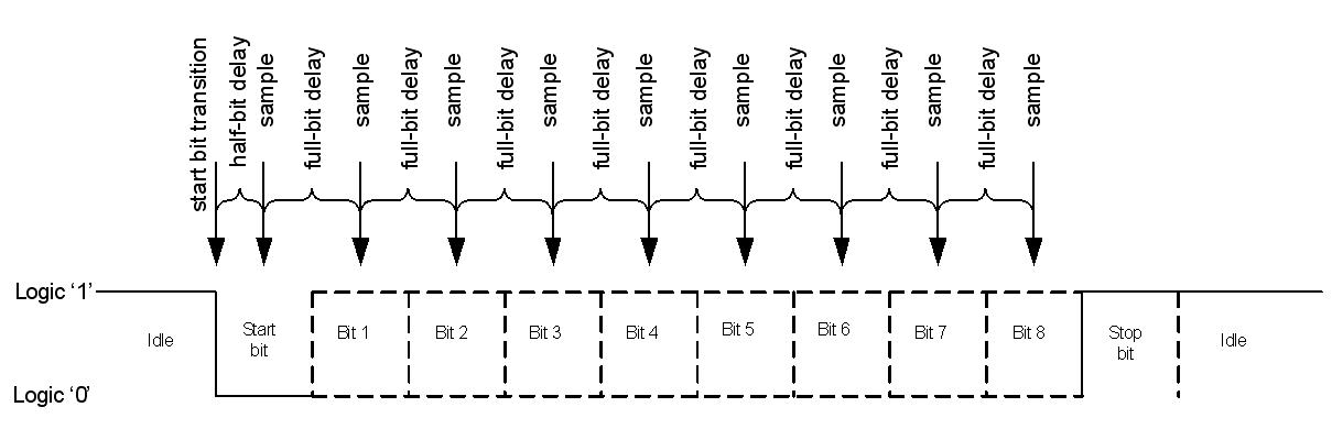
Figure 1. RS-232 Logic Level Signal Sample and Delay
Contributing factors to sampling error include the initial response delay to the start bit,
the half-bit and full-bit delay inaccuracies, and the transmitter and receiver clock tolerances.
Each factor contributes a small Δt from the ideal sample point of each bit.
These deviations accumulate over the entire data frame and can shift the sample point
before or after a data bit position, resulting in data recovery errors.
Some analysis is required to assure reliable communication.
Initial Response Delay
The initial response delay tird is the maximum time between the start bit’s transition and its detection.
It is determined by how often the receive pin is polled.
Therefore, the number of instructions executed by the microcontroller between
polling samples influences the size of the initial response delay.
tird contributes a one-time sample offset to each data frame.
Figure 2 illustrates the timing errors.
Use equation (1) to calculate the time delay provided by the polling routine.
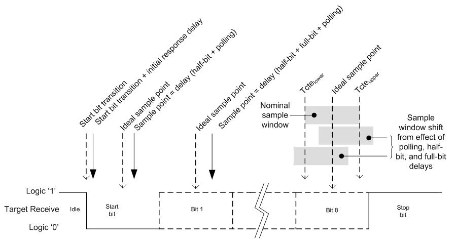
Figure 2. Sample Point Change
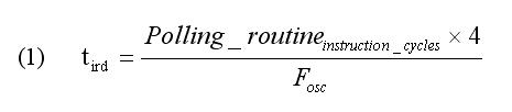
For example, a nominal clock frequency Fosc of 4MHz and 3 instruction cycles in the polling routine results in a tird of 3us.
Receive Half-Bit and Full-Bit Delays
The receive half-bit and full-bit delays determine the number of instruction cycles required for any oscillator and bit rate combination
(see also the C18 library documentation, Chapter 3.6). Equations (2) and (3) define these relationships, respectively.
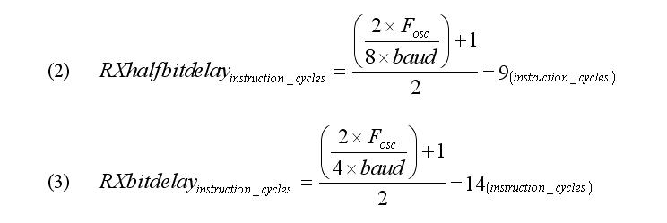
For example, a nominal clock frequency Fosc of 4MHz and a baud rate of 9600bps
require a half-bit delay of 44 instruction cycles and a full-bit delay of 91 instruction cycles.
Use equations (4) and (5) to calculate the time delay provided by the half-bit and full-bit instruction cycle delays, respectively.
For the example above, the half-bit time delay is 53us, and the full-bit time delay is 105us.
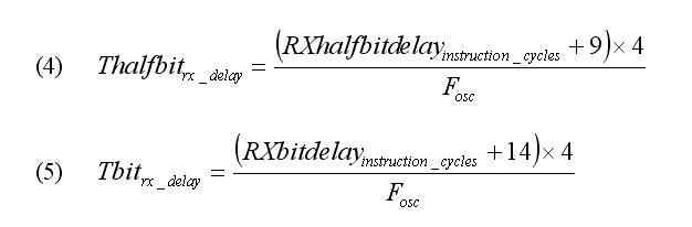
For received data at 9600bps, the total time period (1 start bit, 8 data bits) is 937.5us,
with the last data bit’s center point at 885.4us.
Sampling the incoming data requires 1 Thalfbit and 8 Tbit delays, totaling 893us.
The sample point of the last data bit is offset by approximately 7.6us from the center of the bit period.
Clock Tolerance Error
The clock variation between the transmitter and receiver also contribute to the sampling error.
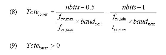
Clock error Tcte is the time between the sample point and the nth data bit of the transmitted data frame.
The sample window bounded by Tcteupper and Tctelower varies,
since microcontroller internal oscillators can vary by ±2% at ambient and ±10%
over the operational temperature range.
fmax and fmin are the worst case clock frequencies in the application’s environment.
Equations (6) and (7) determine if the final sample occurs before the end of the nth bit of the data frame.
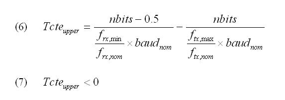
nbits is the number of bits in the packet (including start and data bits).
Equations (8) and (9) ensure that the sample takes place after the nth bit begins.
Assume a host transmit bit rate of 9600bps, 9 bits to recover (1 start bit, 8 data bits),
and a 4MHz clock with an accuracy of ±2%.
The receiving microcontroller’s clock of 4MHz also has an accuracy of ±2%.
Using equation (6) and (8) results in Tcteupper = -15.6us and Tctelower = 17.7us,
meeting the timing boundary conditions in equation (7) and (9).
With the transmit clock accuracy decreased to ±4 %, Tcteupper = 2.0us and Tctelower = 0us,
failing the boundary requirements, resulting in communication errors at the worst case clock frequencies.
Total Receive Error
Total receiver error Ttre is the sum of the initial response delay,
the half-bit and full-bit delays, and the clock tolerance error.
In effect, the sample window, bounded by the clock variation,
is shifted in time due to the accumulation of timing errors.
This shift can cause the sample window to fall outside the data bit boundaries,
resulting in communication errors.
Equations (10) and (11) determine if the final sample occurs before the end of the nth bit of the data frame.
Equations (12) and (13) ensure that the sample takes place after the nth bit begins.
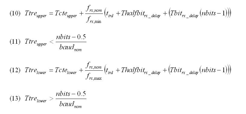
Expanding on the prior example, assume a host transmit bit rate of 9600bps,
9 bits to recover (1 start bit, 8 data bits), and a 4MHz clock with an accuracy of ±2%.
The receiving microcontroller’s 4MHz clock has an accuracy of ±2%.
Applying the results from equations (1), (4), (5), (6) and (8),
in equations (10) and (12) results in Ttreupper = -15.6us and Ttrelower = 17.7us,
meeting the timing boundary conditions in equation (11) and (13).
Accumulated timing effects can move the sample point to the edge of the bit period.
Noise on the line or capacitive effects altering the signal edge rate
can further reduce the sample margin until data is not reliably recovered.
Transmission Full-Bit Delay Error
Data transmission from the target also introduces timing errors from the full-bit delay inaccuracy and clock tolerance.
The transmit full-bit delay, equation (14), determines the number of instruction cycles required
for any oscillator and bit rate combination.
Equation (15) calculates the time delay provided by the full-bit instruction cycle delay.

For a microcontroller clock frequency Fosc of 4MHz and a baud rate of 9600bps,
a full-bit delay of 93 instruction cycles is required. The full-bit time delay is 105us.
Transmission timing errors accumulate as the start bit, 8 data bits,
and stop bit are transmitted and may impact the ability of the host receiver to recover the data.
Conclusion
A conservative timing margin must be maintained to ensure reliable data transfer.
If high bit rates are required, a tight clock tolerance enhances the timing margin.
Increasing the clock frequency reduces the software half-bit and full-bit delay inaccuracies.
Reducing the serial data rate provides longer bit periods, increasing the timing margin.
Using software UART is not without pitfalls.
But, once the contributing error factors are understood and ameliorated,
a reliable serial communication port can be implemented using any pair of GPIO pins.

 浙公网安备 33010602011771号