A brief CRC tutorial
https://www.kernel.org/doc/Documentation/crc32.txt

A brief CRC tutorial.

A CRC is a long-division remainder.
You add the CRC to the message, and the whole thing ( message+CRC ) is a multiple of the given CRC polynomial.
To check the CRC, you can either check that the CRC matches the recomputed value,
*or* you can check that the remainder computed on the ( message+CRC ) is 0.
This latter approach is used by a lot of hardware implementations, and is why so many protocols put the end-of-frame flag after the CRC.


It's actually the same long division you learned in school, except that
- We're working in binary, so the digits are only 0 and 1, and
- When dividing polynomials, there are no carries.  Rather than add and subtract, we just xor.
  Thus, we tend to get a bit sloppy about the difference between adding and subtracting.

Like all division, the remainder is always smaller than the divisor.
To produce a 32-bit CRC, the divisor is actually a 33-bit CRC polynomial.

Since it's 33 bits long, bit 32 is always going to be set, so usually the CRC is written in hex with the most significant bit omitted.
(If you're familiar with the IEEE 754 floating-point format, it's the same idea.)

Note that a CRC is computed over a string of *bits*, so you have to decide on the endianness of the bits within each byte.
To get the best error-detecting properties, this should correspond to the order they're actually sent.
For example, standard RS-232 serial is little-endian; the most significant bit (sometimes used for parity) is sent last.
And when appending a CRC word to a message, you should do it in the right order, matching the endianness.

Just like with ordinary division, you proceed one digit (bit) at a time.
Each step of the division you take one more digit (bit) of the dividend and append it to the current remainder.
Then you figure out the appropriate multiple of the divisor to subtract to being the remainder back into range.
In binary, this is easy - it has to be either 0 or 1, and to make the XOR cancel, it's just a copy of bit 32 of the remainder.

When computing a CRC, we don't care about the quotient, so we can throw the quotient bit away,
but subtract the appropriate multiple of the polynomial from the remainder and we're back to where we started,
ready to process the next bit.

A big-endian CRC written this way would be coded like:

  for ( i = 0; i < input_bits; i++ )
  {
    multiple = remainder & 0x80000000 ? CRCPOLY : 0;
    remainder = ( remainder << 1 | next_input_bit( ) ) ^ multiple;
  }
Notice how, to get at bit 32 of the shifted remainder, we look at bit 31 of the remainder *before* shifting it.

But also notice how the next_input_bit() bits we're shifting into the remainder don't actually affect any decision-making
until 32 bits later.

Thus, the first 32 cycles of this are pretty boring.
Also, to add the CRC to a message, we need a 32-bit-long hole for it at the end,
so we have to add 32 extra cycles shifting in zeros at the end of every message,

These details lead to a standard trick:
rearrange merging in the next_input_bit() until the moment it's needed.
Then the first 32 cycles can be precomputed, and merging in the final 32 zero bits to make room for the CRC can be skipped entirely.
This changes the code to:
  for ( i = 0; i < input_bits; i++ )
  {
    remainder ^= next_input_bit( ) << 31;
    multiple = ( remainder & 0x80000000 ) ? CRCPOLY : 0;
    remainder = ( remainder << 1 ) ^ multiple;
  }
With this optimization, the little-endian code is particularly simple:
  for ( i = 0; i < input_bits; i++ )
  {
    remainder ^= next_input_bit( );
    multiple = ( remainder & 1 ) ? CRCPOLY : 0;
    remainder = ( remainder >> 1 ) ^ multiple;
  }
The most significant coefficient of the remainder polynomial is stored in the least significant bit of the binary "remainder" variable.
The other details of endianness have been hidden in CRCPOLY (which must be bit-reversed) and next_input_bit().

As long as next_input_bit is returning the bits in a sensible order, we don't *have* to wait
until the last possible moment to merge in additional bits.

We can do it 8 bits at a time rather than 1 bit at a time:
  for ( i = 0; i < input_bytes; i++ )
  {
    remainder ^= next_input_byte( ) << 24;
    for ( j = 0; j < 8; j++ )
    {
      multiple = ( remainder & 0x80000000 ) ? CRCPOLY : 0;
      remainder = ( remainder << 1 ) ^ multiple;
    }
  }
Or in little-endian:
  for ( i = 0; i < input_bytes; i++ )
  {
    remainder ^= next_input_byte( );
    for ( j = 0; j < 8; j++ )
    {
      multiple = ( remainder & 1 ) ? CRCPOLY : 0;
      remainder = ( remainder >> 1 ) ^ multiple;
    }
  }
If the input is a multiple of 32 bits, you can even XOR in a 32-bit word at a time and increase the inner loop count to 32.

You can also mix and match the two loop styles, for example doing the bulk of a message byte-at-a-time
and adding bit-at-a-time processing for any fractional bytes at the end.

To reduce the number of conditional branches, software commonly uses the byte-at-a-time table method,
popularized by Dilip V. Sarwate, "Computation of Cyclic Redundancy Checks via Table Look-Up", Comm. ACM v.31 no.8 (August 1998) p. 1008-1013.

Here, rather than just shifting one bit of the remainder to decide in the correct multiple to subtract, we can shift a byte at a time.
This produces a 40-bit (rather than a 33-bit) intermediate remainder, and the correct multiple of the polynomial
to subtract is found using a 256-entry lookup table indexed by the high 8 bits.

(The table entries are simply the CRC-32 of the given one-byte messages.)

When space is more constrained, smaller tables can be used, e.g. two 4-bit shifts followed by a lookup in a 16-entry table.

It is not practical to process much more than 8 bits at a time using this technique,
because tables larger than 256 entries use too much memory and, more importantly, too much of the L1 cache.

To get higher software performance, a "slicing" technique can be used.
See "High Octane CRC Generation with the Intel Slicing-by-8 Algorithm",
ftp://download.intel.com/technology/comms/perfnet/download/slicing-by-8.pdf

This does not change the number of table lookups, but does increase the parallelism.
With the classic Sarwate algorithm, each table lookup must be completed before the index of the next can be computed.

A "slicing by 2" technique would shift the remainder 16 bits at a time, producing a 48-bit intermediate remainder.
Rather than doing a single lookup in a 65536-entry table, the two high bytes are looked up in two different 256-entry tables.
Each contains the remainder required to cancel out the corresponding byte.
The tables are different because the polynomials to cancel are different.
One has non-zero coefficients from x^32 to x^39, while the other goes from x^40 to x^47.

Since modern processors can handle many parallel memory operations,
this takes barely longer than a single table look-up and thus performs almost twice as fast as the basic Sarwate algorithm.

This can be extended to "slicing by 4" using 4 256-entry tables.
Each step, 32 bits of data is fetched, XORed with the CRC, and the result broken into bytes and looked up in the tables.
Because the 32-bit shift leaves the low-order bits of the intermediate remainder zero,
the final CRC is simply the XOR of the 4 table look-ups.

But this still enforces sequential execution: a second group of table look-ups cannot begin
until the previous groups 4 table look-ups have all been completed.
Thus, the processor's load/store unit is sometimes idle.

To make maximum use of the processor, "slicing by 8" performs 8 look-ups in parallel.
Each step, the 32-bit CRC is shifted 64 bits and XORed with 64 bits of input data.
What is important to note is that 4 of those 8 bytes are simply copies of the input data;
they do not depend on the previous CRC at all.
Thus, those 4 table look-ups may commence immediately, without waiting for the previous loop iteration.

By always having 4 loads in flight, a modern superscalar processor can be kept busy and make full use of its L1 cache.

Two more details about CRC implementation in the real world:

Normally, appending zero bits to a message which is already a multiple of a polynomial produces a larger multiple of that polynomial.
Thus, a basic CRC will not detect appended zero bits (or bytes).
To enable a CRC to detect this condition, it's common to invert the CRC before appending it.
This makes the remainder of the message+crc come out not as zero, but some fixed non-zero value.
(The CRC of the inversion pattern, 0xffffffff.)

The same problem applies to zero bits prepended to the message, and a similar solution is used.
Instead of starting the CRC computation with a remainder of 0, an initial remainder of all ones is used.
As long as you start the same way on decoding, it doesn't make a difference.
/* bit by bit
 * The width of the CRC calculation and result.
 * Modify the typedef for a 16 or 32-bit CRC standard.
 */
typedef uint8_t crc;

#define WIDTH (8 * sizeof(crc))
#define TOPBIT (1 << (WIDTH - 1))
#define POLYNOMIAL  0x81

crc crcSlow( uint8_t const message[ ], int nBytes )
{
  crc remainder = 0;

  /*
   * Perform modulo-2 division, a byte at a time.
   */
  for ( int byte = 0; byte < nBytes; ++byte )
  {
    /*
     * Bring the next byte into the remainder.
     */
    remainder ^= ( message[ byte ] << ( WIDTH - 8 ) );

    /*
     * Perform modulo-2 division, a bit at a time.
     */
    for ( uint8_t bit = 8; bit > 0; --bit )
    {
      /*
       * Try to divide the current data bit.
       */
      if ( remainder & TOPBIT )
      {
        remainder = ( remainder << 1 ) ^ POLYNOMIAL;
      }
      else
      {
        remainder = ( remainder << 1 );
      }
    }
  }

  /*
   * The final remainder is the CRC result.
   */
  return ( remainder );
} /* crcSlow() */
Cycling Redundancy Checks (CRCs) are a common form of checking for the integrity of data on transmission or storage.
The XMOS XS1 instruction set has dedicated instructions for computing and checking CRCs. In this section we discuss how to use the CRC instructions.
CRC mathematics
A CRC is defined as the remainder of a division of two polynomials in GF-2.
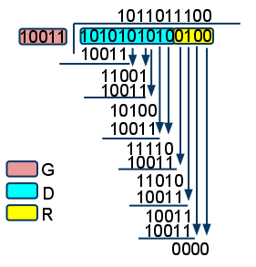
The simplest way to visualise a CRC is to use a long division
Put the input string down at the top (first bit on the left, last bit on the right), then start dividing.
A division step is to perform an an XOR with the polynomial if the left-most bit is 1, making the left-most bit 0.
Then remove the left-most bit, and repeat.
The following example divides 110100110 by 1100 using XOR arithmetic (GF-2), resulting in a remainder of 1110:
110100110 <--- Input
1100 .  . <--- XOR with divisor (4 Bits)
 0010.  .
 0000.  .
  0100  .
  0000  .
   1001 .
   1100 .
    1011.
    1100.
     1110<- remainder
When all bits of input have been shifted in, the result is guaranteed four bits; these four bits are the CRC.
CRC using digital electronics
Instead of using the mathematical description, many protocols specify the CRC as a linear-feedback-shift-register,
which is the common implementation in digital electronics.
In this implementation, the remainder is commonly shifted from left to right,
and the right most bit (the first bit of data that came in) is XORed in in the bit locations marked by the CRC.
The above example uses a polynomial of 1100, which means that the bit 3 has to be XORed over bits 3 and 2.
The computation of the remainder would progress as follows: 110100110-1011
Initial remainder r[0..3]           1011
XOR r[3] onto r[2] and r[3]:        1000

Shift right, shifting next data in: 0100
XOR r[3] onto r[2] and r[3]:        0100

Shift right, shifting next data in: 0010
XOR r[3] onto r[2] and r[3]:        0010

Shift right, shifting next data in: 1001
XOR r[3] onto r[2] and r[3]:        1010

Shift right, shifting next data in: 1101
XOR r[3] onto r[2] and r[3]:        1110

Shift right, shifting next data in: 0111
ote that the answer is the same, and that the bits are written down in a reverse order.
The polynomial
The CRC above uses the polynomial x^0 + x^1 + x^4;
terms 0, 1, and 4 are used, which can be represented as 11001 (with the left most bit denoting the presence of x^0),
or 10011 (with the rightmost bit denoting the presence of x^0).
For a polynomial of order N, the term x^N must always be present, and hence when specifying a polynomial, this bit is not specified.
Hence, the polynomial x^0 + x^1 + x^4 is known as either 1100 or 0011,
where the former is the reverse representation, and the latter is the normal representation.
For example, the polynomial used for Ethernet is
x^32 + x^26 + x^23 + x^22 + x^16 + x^12 + x^11 + x^10 + x^8 + x^7 + x^5 + x^4 + x^2 + x^1 + x^0,
or (1) 0000 0100 1100 0001 0001 1101 1011 0111,
which is 0x04C11DB7 in normal representation, or 0xEDB88320 in reverse notation.
When using the XMOS XS1 instructions, you should always specify your polynomial in reverse order (eg, 0xEDB88320 for Ethernet).
The length of the polynomial is implicit in the polynomial. (the term x^0 is always part of the polynomial)
Bit ordering
In order to efficiently compute a CRC, the XMOS XS1 processor will fold 8 or 32 bits into the CRC at a time.
The CRC8 instruction will fold in 8 bits (specified with the ‘first’ bit in bit 0, and the last bit in bit 7), and folds them in.
The CRC32 instruction will fold in 32 bits starting with bit 0, all the way to bit 31.
If the bit ordering of data stored in memory or data coming from your input stream is different,
then the BITREV and BYTEREV instructions can be used to alter the order.
BITREV will swap all bits form left to right.
BYTEREV swaps the byte in a word.
A combination of the two can swap all bits in a byte.
The initial value
In the examples above, we have started the computation of the remainder with the first few data bits already in place.
Normally, a CRC computation would start with an initial value, such as ‘0’, and then the CRC computation takes place. on the data.
The two most common starting patterns are all zeroes, or all ones.
When starting with four zeroes on our previous example, the first four operations will not do anything, until the first four data bits are shifted in:
1111110100110 <--- Input
1100   . <--- XOR with divisor (4 Bits)
 0111  .
 0000  .
  1111 .
  1100 .
   0110.
   0000.
    1101
    1100
    etc.
Note that the pattern of applying XOR or not is input data independent in the first four steps.
In the case of the polynomial shown here (1100), the XOR happens in the first and third step. Hence, the data is XORed with all zeroes:
1111ABCD
1100
 0000
  1100
   0000
--------- XOR
0000ABCD
Hence, the first step can be skipped.
For all polynomials the first step will comprise an XOR with some constant value.
In the case of the Ethernet polynomial, the first step happens to be an XOR with all ones, which is simply inverting the first dataword.
For any start value, the first steps are data independent, and a constant XOR value can be computed.
The CRC that is transmitted
The final CRC of a polynomial of order N is N bits, and these are either transmitted plain, or they may have to be inverted.
Computing a CRC over an odd number of bits
Many CRCs are computed over a bit-stream which is a whole number of bytes long.
In this case, the CRC32 instruction can be used on all words of data until there are 0, 1, 2, or 3 bytes left,
whereupon a CRC8 instruction is applied 0, 1, 2, or 3 times.
There are cases where the number of bits is not a multiple of 8;
for example in the case of a CAN packet.
In that case the most efficient solution is to prepend an N-bit packet with 32-(N mod 32) zero bits.
This will align the end of the packet onto a 32-bit boundary, meaning that CRC32 instructions can be used all the way.
The only problem is to realign each word. This can be done with a MACCU as is shown in an earlier chapter of this document.
Note that if the alignment of the final bit is not known in advance, then up to eight final bits will have to be folded in one at a time.
XS1 CRC instructions
The XMOS XS1 instructions has two instructions to compute a CRC.
- The CRC instruction computes a new remainder, given a polynomial and a a current remainder, and 32 input bits.
- The CRC8 instruction computes a new remainder, given a polynomial and a a current remainder, and 8 input bits. In addition, it shifts 8 bits outs of the data word, enabling multiple CRC8 instructions to be chained to fold 16 or 24 bits into the CRC.

 浙公网安备 33010602011771号