STM32 CRC-32 Calculator Unit

AN4187 - Using the CRC peripheral in the STM32 family
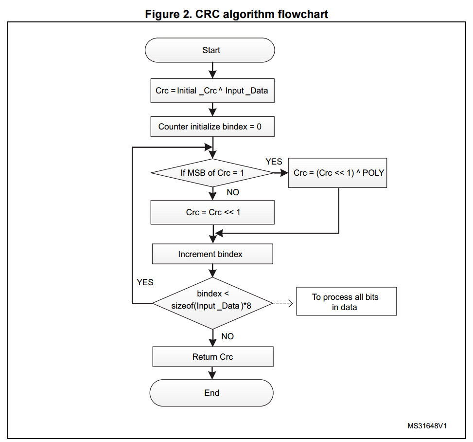
At start up, the algorithm sets CRC to the Initial_Crc XOR with the Input_Data.
Once CRC MSB is equal to one, the algorithm shifts CRC one bit to the left and XORs it with the POLY.
Otherwise, it only shifts CRC one bit to the left.
Figure 3 shows the step-by-step algorithm execution for the following conditions:
– Input_Data = 0xC1
– POLY = 0xCB
– Initial_Crc = 0xFF

All STM32 devices implement a CRC peripheral as described in Section 1.1.
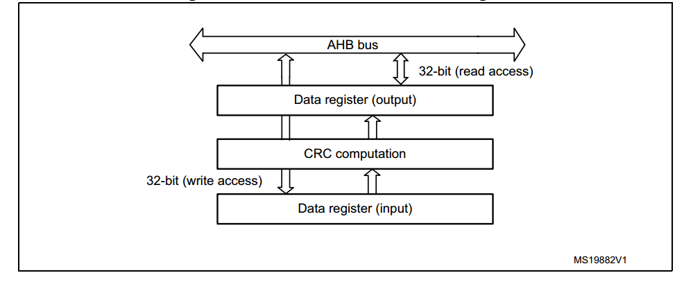
The CRC calculation unit has a single 32-bit read/write data register (CRC_DR).
It is used to input new data (write access) and hold the result of the previous CRC calculation (read access).
Each write operation to the data register creates a combination of the previous CRC value (stored in CRC_DR) and the new one.
Figure 4. CRC calculation unit block diagram
To compute a CRC of any supported data, you must follow these steps:
1. Enable the CRC peripheral clock via the RCC peripheral.
2. Set the CRC Data Register to the initial CRC value by configuring the Initial CRC value register (CRC_INIT).(a)
3. Set the I/O reverse bit order through the REV_IN[1:0] and REV_OUT bits respectively in CRC Control register (CRC_CR).(a)
4. Set the polynomial size and coefficients through the POLYSIZE[1:0] bits in CRC Control register (CRC_CR)
and CRC Polynomial register (CRC_POL) respectively.(b)
5. Reset the CRC peripheral through the Reset bit in CRC Control register (CRC_CR).
6. Set the data to the CRC Data register.
7. Read the content of the CRC Data register.
8. Disable the CRC peripheral clock.
In firmware package, the CRC_usage example runs the CRC checksum code computing an array data (DataBuffer) of 256 supported data type.
For a full description, please refer to the file Readme.txt in the CRC_usage folder.
a. Applicable only for STM32F0xx and STM32F3xx devices
b. Applicable only for STM32F3xx devices

 浙公网安备 33010602011771号