STM32F105 PA9/OTG_FS_VBUS Issues
ISSUE 1: PA9/OTG_FS_VBUS +5V Tolerance
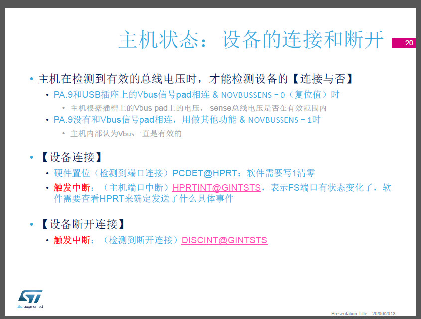
When the STM32F105 is configured as a USB device, the PA9/OTG_FS_VBUS is used to detect the presense of a USB host.
ST Micro evaluation designs show the PA9/OTG_FS_VBUS pin connected to +5 VBUS through a zero ohm resistor.
ST Micro evaluation designs show the PA9/OTG_FS_VBUS pin connected to +5 VBUS through a zero ohm resistor.
There are two potential problems with this approach.
The first potential problem is that the PA9/OTG_FS_VBUS input, although it is 5V tolerant,
may be damaged (as per ST support) if connected to +5V when the STM32F105 VDD is 0V.
This may occur in both self powered and host powered applications.
This will occur in a self-powered application when power is switched off/unplugged
while the USB connection to the Host is still active.
This will occur in a host powered application during the time it takes the VDD regulator
to come up to it's regulated output voltage.
to come up to it's regulated output voltage.
Some designers have recommended a series resistor between the PA9/OTG_FS_VBUS pin and +5V VBUS.
See ISSUE 2. To avoid the potential to damage the PA9/OTG_FS_VBUS pin, ST support has recommeded
connecting the pin to VDD instead.
connecting the pin to VDD instead.
I have verified that this will work with USB application code as well as DFU bootloader mode.
One of the problems with this approach is that you lose the ability to detect the presense of the USB host
if you are a self-powered device.
One of the problems with this approach is that you lose the ability to detect the presense of the USB host
if you are a self-powered device.
In that case, I think the only solution is to drive PA9/OTG_FS_VBUS input from the output of a +3V3 LDO
(such as digikey AP7313-33SAG-7DICT-ND) which is powered from +5V VBUS.
(such as digikey AP7313-33SAG-7DICT-ND) which is powered from +5V VBUS.
ISSUE 2: PA9/OTG_FS_VBUS Current Sink
Take the evaluation design or your own design with the STM32F105
and put a milliamp-meter in-between PA9/OTG_FS_VBUS and +5V VBUS.
Plug and unplug your USB connection to the host up to 50 times.
Every once in a while, you'll see that the PA9/OTG_FS_VBUS input is sinking 45 mA.
Connect the PA9/OTG_FS_VBUS pin to +3V3 VDD and you'll also measure 45 mA.
This pin becomes a true 45 mA current sink.
If you happen to be in DFU mode and running the DFUse demo application
you'll see that you are in fact connected and the USB interface is still working properly.
Disconnect one lead from your meter and reconnect and you'll see that the pin is still sinking 45 mA.
The only way to stop this condition is to power down the STM32F105 and power up again
or you may have to power cycle a few times.
If you happen to have a 1K resistor in series with PA9/OTG_FS_VBUS and +5V VBUS
when this current sink condition is active,
the USB interface will not be active - no DFU boot loader,
no USB device application code will work.
Here's an experiment I tried while PA9/OTG_FS_VBUS pin is exhibiting this 45 mA current sink behaviour
and I am in DFU mode while connected to host running the DFUse application.
I have a 0-100 ohm potentiometer in series with PA9/ORG_FS_VBUS and +3V3.
If I set the series pot to 0 ohm, I measure 45 mA and USB is ACTIVE.
If while I measure the V at PA9 while increasing the R,
the USB will go inactive at PA9 V = 1.2V with 39 mA and 98 ohm R.
While monitoring V at PA9, the USB will remain inactive until I decrease R such
that PA9 V = 1.6V with a current into PA9 of 45 mA.
I'm waiting to hear back from ST support on this.
Will the STM32F105 be damaged if our device is powered up in a server application
and PA9/OTG_FS_VBUS pin is sinking 45 mA for 6 months straight?
Should we switch to the STM32F103 and lose the USB DFU cabibility? Questions and more questions.

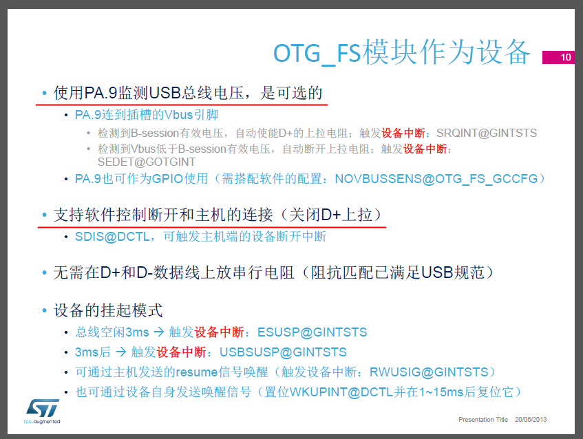
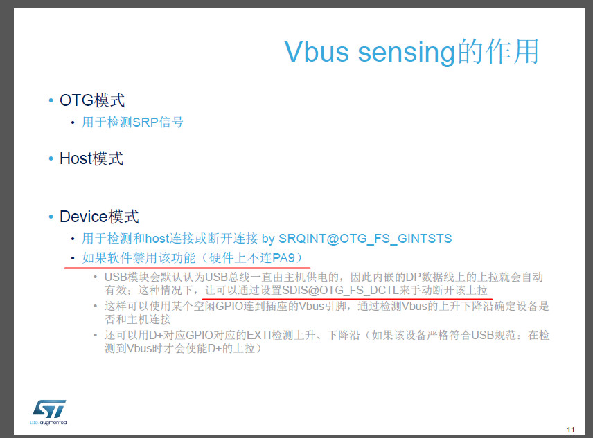
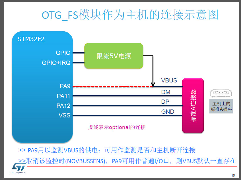
The VBUS pin can be freed by disabling the VBUS sensing option.
This is done by setting the NOVBUSSENS bit in the OTG_FS_GCCFG register.
In this case the VBUS is considered internally to be always at VBUS valid level (5 V).

 浙公网安备 33010602011771号