USB PIC Programmer (Brenner8)
http://uzzors2k.4hv.org/index.php?page=usbpicprog

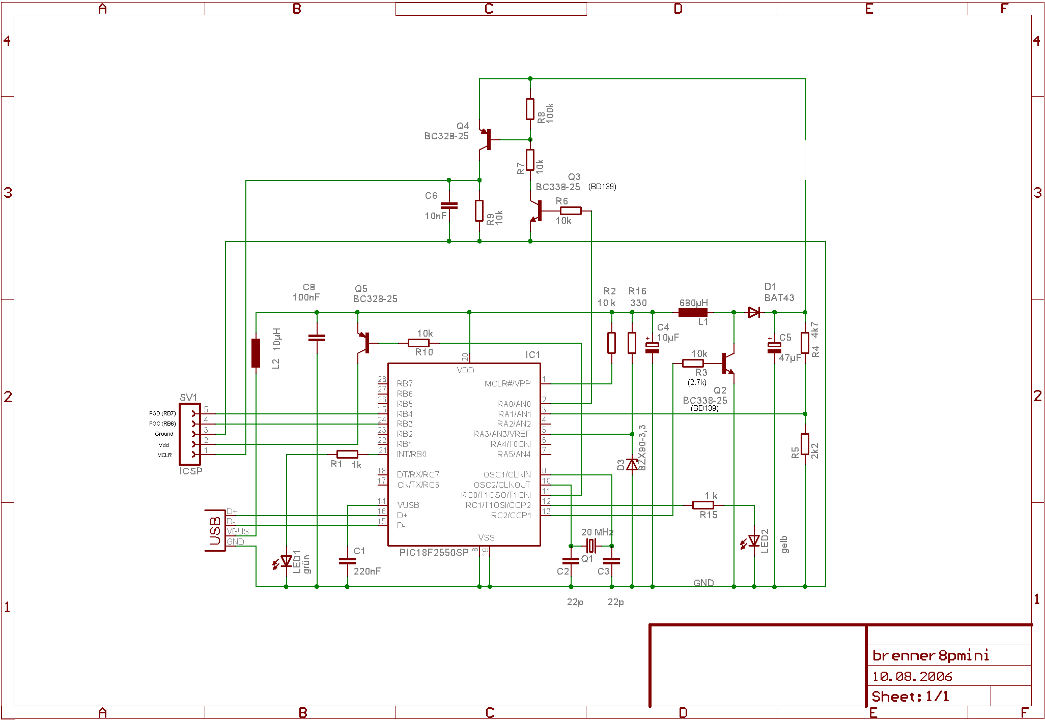
My Tait Serial programmer works alright, but not every computer has a parallel port, and these days they're almost extinct. Most laptop don't even have a serial port! Thinking ahead a USB programmer seems like a smart investment. Fortunately someone has made a diy version, the Brenner8. It consists of a PIC18F2550 and some transistors, nothing more. The PIC18F2550 even runs a boost-converter supplying the MCLR voltage, so all power is supplied through USB! Very elegant. There are several variations to the main design, but I chose the mini ICSP version. Since I only program 18 pin PICs the whole 40 pin ZIF socket would be overkill, and additional sockets can be added to the ICSP connector easily.
The programmer is pretty easy to put together, the catch is the PIC18F2550 which needs to be programmed with a bootloader. Any parallel or serial port programmer can do this, I usedmy previous PIC programmer and this programming software. Remember to invert VDD and VPP, and that the PIC18F2550 MCLR voltage is 12.5V maximum compared 13.6V used in the Tait programmer. I had to use a 15k pull down on PGM (pin 26) and a 100 ohm resistor in series with PGD (pin 28) + 100pF cap to ground on PGD line. PGC is pin 27, MCLR pin 1, Vdd is pin 20 and ground is pins 8 and 19. The bootloader hex is bootloader_0_20mhz.hex if using a 20 MHz clock which we are. All the software and firmware required can be found in USBurn 1.5. Download and install it. Updated firmware and bootloader software can be found at thecreator's website.
Once the PIC18F2550 is programmed, build the circuit as shown above. I had problems with transistors Q2 and Q3, but using BD139's instead solved it. Q2's base resistor had to be changed to 2.7k. Component values are fairly non-critical, except for R4, R5, Q1 and D3. However R4, R5, and D3 can be compensated for in the USBurn software. Once built, put the programmed PIC18F2550 into the programmer and plug it in. The computer should recognize the device, and prompt you to install drivers. Click through until you can select a location to install the the drivers from, then browse to the drivers folder in the USBurn folder. Select it and windows should install the drivers. Once installed, go to control panel -> system -> hardware -> device manager -> other devices -> PICbrenner8 (sprut). Go to properties, power management and do not allow windows to turn off device to save power. Your programmer is now installed.

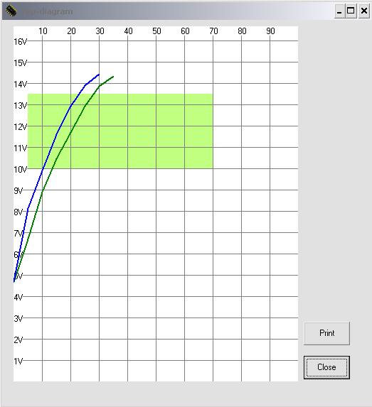
he next step is to calibrate the programmer. Open USBurn and go to options -> Calibration/Test. First turn the on various voltages and test for 5V on all but Vpp. For SDATA ensure that the programmer reads the correct data in. Once the main signal points check out, it's time for MCLR voltage calibration. Turn on Vpp, and measure the zener diode voltage drop at pin 5 with a multimeter. Enter this voltage into the zener diode section (Z-voltage). If you used a 4.7k and 2.2k resistor the U-divider can be left untouched, otherwise adjust it to reflect the resistor divider' input to output voltage ratio. Once this is done turn on both Vdd and Vpp, then hit "3: auto-adjust offset and gain". Now push the 13V button, and finally ">" button which measures Vpp. If calibrated correctly the voltage should be around 13V, and the voltage measured by USBurn should be almost equal to the multimeter voltage. Push the "graph" button to see that the boost converter is working properly. The correct graph will look something like the one to the right. As long as the lines pass through the green area the boost converter section is working correctly.
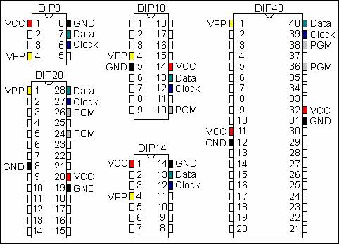
Your Brenner8 should now be ready for use! See PIC programming specifications for details on programming PICs in various packages.


 浙公网安备 33010602011771号