ICD2 VPP limiter for new PIC microcontrollers.
http://www.circuitsathome.com/mcu/pic_vpp_limiter
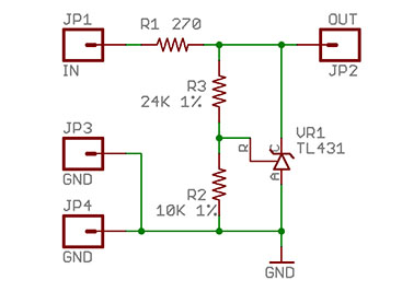
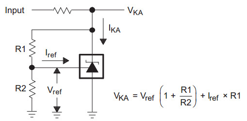
VOUT = 2.5V * ( 1 + 24/10 ) = 2.5 * 3.4 = 8.5V
Newer PIC18s, such as my current favorite – PIC18F26K20, don’t like to be programmed with 12V. The datasheet maximum is 9V. Older Microchip programmers/debuggers, such as PicKit and ICD 2, do not support variable programming voltage. When you start a MPLAB project consisting of K-series PIC18 and ICD 2 debugger, you will get a warning and suggested VPP limiting circuit schematic. In this article I’m describing this very circuit, so you can build it beforehand.
The circuit is as easy as it gets. It is TL431 programmable voltage reference configured for 8.5V cutoff. If you are not comfortable having VPP so close to specified maximum, change voltage divider R2R3. Bear in mind that minimum VPP for new PIC18s is VDD+4.5V; if you are powering your PIC from 3.3V (max.VDD), minimum VPP is 7.8V.
To build this circuit, you can use a PCB, or use a small piece of prototyping board. I solder right-angle headers into ground pads; this way, the limiter can be inserted vertically, saving precious breadboard space.
I suggest checking circuit operation after you build it. You will need bench power supply (or any known voltage source of 9V or more) and a voltmeter. The procedure for bench power supply is as follows:
- Set your power supply to minimum voltage and current.
- Set voltmeter range to 20V DC.
- Connect circuit IN to the power supply, circuit OUT to the voltmeter, all 3 grounds (power supply, voltmeter, and circuit ) together.
- Add some voltage on power supply. If it starts showing overcurrent, add little current (but just a little; the current when to become suspicious and start looking for shorts is 30mA).
- The voltmeter should follow power supply as you add voltage until you reach 8.5V. At 8.5V voltmeter should stop. Continue adding voltage on power supply until you reach 12.5-13V. If voltmeter still shows 8.5V, your circuit is working.
Now, when your know circuit is operational, it’s time to use it. Connect IN to MCLR/VPP signal coming from the programmer, connect OUT to MCLR/VPP of your PIC, connect GND to ground. The last connection is as essential as other two – if ground is not connected, the circuit will bypass input voltage to output without change.

 浙公网安备 33010602011771号