

USB device layout, descriptors, interface alternate setting
http://msdn.microsoft.com/en-us/library/windows/hardware/hh920375(v=vs.85).aspx
A Universal Serial Bus (USB) device defines its capabilities and features through configurations, interfaces, alternate settings, and endpoints. This topic provides a high-level overview of those concepts. For details, see the USB specifications atUniversal Serial Bus Documents.
A USB configuration defines the capabilities and features of a device, mainly its power capabilities and interfaces. The device can have multiple configurations, but only one is active at a time. The active configuration isn't chosen by the USB driver stack, but by a client of the driver stack, such as the device driver. A configuration can have one or more USB interfaces that define the functionality of the device. Typically, there is a one-to-one correlation between a function and an interface. However, certain devices expose multiple interfaces related to one function. In that case, the device can have an interface association descriptor (IAD). An IAD groups together interfaces that belong to a particular function.
Each interface contains one or more endpoints, which are used to transfer data to and from the device. In addition, the interface contains alternate settings that define the bandwidth requirements of the function associated with the interface. To sum up, a group of endpoints form an interface, and a set of interfaces constitutes a configuration in the device.
During device configuration, the USB client driver for the device must select a configuration, one or more or interfaces within that configuration, and an alternate setting for each interface. Most USB devices don't provide multiple interfaces or multiple alternate settings. For example, the OSR USB FX2 Learning Kit device has one interface with one alternate setting and three endpoints. For more information about the learning kit, see OSR Online.
Single interface device
This diagram shows the configuration of a device with a single interface:
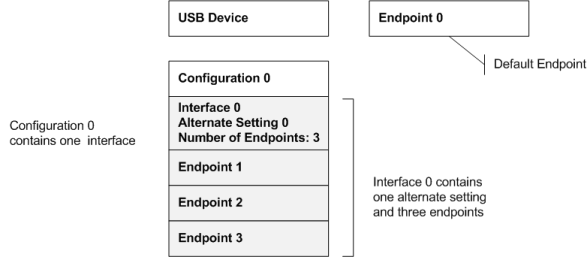
In this example, the diagram shows Endpoint 0, called the default endpoint. All USB devices must have a default endpoint that is used for control transfers (see USB Control Transfer). Configuration 0 has one interface: Interface 0 with one alternate setting. Alternate Setting 0 uses all three endpoints in the interface.
Multiple-interfaces device
For multifunction devices, the device has multiple interfaces. To use a particular function or an interface, the client driver selects the interface and an associated alternate setting. Consider a multi-function USB device such as a webcam. The device has two functions, video-capture (camera) and audio input (microphone). The device defines an endpoint in a video interface that streams video. The device has another endpoint in a separate interface that takes audio input through the microphone. The configuration of the device includes both of these interfaces.
This diagram shows the configuration of the webcam device:
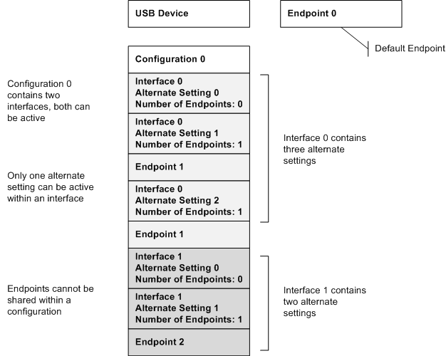
In this example, the diagram shows the default endpoint. Configuration 0 has two interfaces: Interface 0 and Interface 1.
Interface 0 has three alternate settings. Only one of the alternate settings is active at any given time.
Notice that Alternate Setting 0 doesn't use an endpoint, whereas Alternate Settings 1 and 2 use Endpoint 1.
Typically, a video camera uses an isochronous endpoint for streaming. For that type of endpoint, when the endpoint is in use, bandwidth is reserved on the bus. When the camera is not streaming video, the client driver can select Alternate Setting 0 to conserve bandwidth. When the webcam is streaming video, the client driver can switch to either Alternate Setting 1 or Alternate Setting 2, which provides increasing levels of quality and consumes increasing bus bandwidth. Interface 1 has two alternate settings.
Similar to Interface 0, Alternate Setting 0 doesn't use an endpoint. Alternate Setting 1 is defined to use Endpoint 2.
Endpoints can't be shared between two interfaces within a configuration. The device uses the endpoint address to determine the target endpoint for a data transfer or endpoint operation, such as pipe reset. All those operations are initiated by the host.
Information about device configuration, interface, and endpoints are described in data structures called descriptors. For more information, see USB Descriptors.
Before you start using the device, get information about the device layout. Usbview.exe is an application that enables you to browse all USB controllers and the USB devices that are connected to them. For each connected device, you can view the device, configuration, interface, and endpoint descriptors to get an idea about the capability of the device.
You can install USBView from the Install Debugging Tools for Windows package in the Windows Software Development Kit (SDK). Typically, USBView is installed in theDebuggers folder in the Windows Driver Kit (WDK).
http://msdn.microsoft.com/en-us/library/windows/hardware/ff539267(v=vs.85).aspx
A USB device provides information about itself in data structures called USB descriptors. This section provides information about various descriptors that a client driver can obtain from a USB device.
The host obtains descriptors from an attached device by sending various standard control requests (GET_DESCRIPTOR requests) to the default endpoint. Those requests specify the type of descriptor to retrieve. In response to such requests, the device sends descriptors that include information about the device, its configurations, interfaces and the related endpoints. Device descriptors contain information about the whole device. Configuration descriptors contain information about each device configuration. String descriptors contain Unicode text strings.
Every USB device exposes a device descriptor that indicates the device’s class information, vendor and product identifiers, and number of configurations. Each configuration exposes it's configuration descriptor that indicates number of interfaces and power characteristics. Each interface exposes an interface descriptor for each of its alternate settings that contains information about the class and the number of endpoints. Each endpoint within each interface exposes endpoint descriptors that indicate the endpoint type and the maximum packet size.
For example, consider the OSR FX2 board device layout described in USB Device Layout. At device level, the device exposes a device descriptor and an endpoint descriptor for the default endpoint. At configuration level, the device exposes a configuration descriptor for Configuration 0. At interface level, it exposes one interface descriptor for Alternate Setting 0. At the endpoint level, it exposes three endpoint descriptors.
In this section
| Topic | Description |
|---|---|
|
The device descriptor contains information about a USB device as a whole. This topic describes the USB_DEVICE_DESCRIPTOR structure and includes information about how a client driver can send a get-descriptor request to obtain the device descriptor. |
|
|
A USB device exposes its capabilities in the form of a series of interfaces called a USB configuration. Each interface consists of one or more alternate settings, and each alternate setting is made up of a set of endpoints. This topic describes the various descriptors associated with a USB configuration. |
|
|
Device, configuration, and interface descriptors may contain references to string descriptors. This topic describes how to get a particular string descriptor from the device. |
|
|
USB interface association descriptor (IAD) allows the device to group interfaces that belong to a function. This topic describes how a client driver can determine whether the device contains an IAD for a function. |
|
|
Microsoft provides a set of proprietary device classes and USB descriptors, which are called Microsoft OS Descriptors (MODs). This topic provides an overview of MODs. |
http://msdn.microsoft.com/en-us/library/windows/hardware/hh968309(v=vs.85).aspx
This topic describes the steps for issuing a select-interface request to activate an alternate setting in a USB interface. The client driver must issue this request after selecting a USB configuration. Selecting a configuration, by default, also activates the first alternate setting in each interface in that configuration.
Each USB configuration must support one or more multiple USB interfaces. Each interface exposes one or more endpoints that are used to transfer data to and from the device. USB interfaces must have a device-defined, interface index that is used to identify the interface. The interface must also have one or more alternate settings that group the endpoints of the interface. As part of device configuration, the client driver must select one of the alternate settings in the interface. Because endpoints can be shared among alternate settings, only one setting can be active at a given time. After the alternate setting is active, its endpoints become available for data transfers.
For a multiple interface device, two interfaces can be active at a given time. The client driver must activate an alternate setting in each interface. Endpoints are not shared among interfaces and therefore, each simultaneous data transfers can be performed on each interface.
Alternate settings are device-defined and identified with a number called the setting index. The alternate setting at index 0 is called the default alternate setting in this documentation set. An alternate setting is described in a USB_INTERFACE_DESCRIPTOR structure. The structure contains the interface index with which the setting is associated and the number of endpoints defined by the setting. It also contains information about the class specification to which the functionality of the interface conforms. The way, in which endpoints are grouped, depends on the functionality of the device.
For example, an interface exposes two isochronous and two bulk endpoints through three alternate settings (index 0, 1, 2).
The Alternate Setting 0 does not define any endpoint;
Alternate Setting 1 defines the bulk endpoints;
Alternate Setting 2 defines the isochronous endpoints.
Because Alternate Setting 0 has no endpoint, the client driver can select this setting to disable data transfer in order to conserve bandwidth. When either of the other settings is active, the device is ready for data transfers.
Alternate Setting 1 can be used to transfer bulk data.
Alternate Setting 2 can be selected when the device is in streaming mode.
Therefore, alternate settings give the client driver the flexibility of changing the device configuration as and when required.
In this example, the client driver can switch the device functionality from a bulk transfer to streaming, just by selecting an alternate setting.
Alternate settings can also be used to set bandwidth requirements. For an example, see the USB Device Layout.
Windows Driver Foundation (WDF) provides methods in Kernel-Mode Driver Framework andUser-Mode Driver Framework that the client driver can call to select a different alternate setting. KMDF client driver can select a setting by specifying the setting index, interface descriptor of the setting, or by submitting an URB that contains the request. UMDF client driver can only select an alternate setting by specifying its setting index.
After a select-configuration request completes successfully, the previously active alternate setting is deactivated.

 浙公网安备 33010602011771号