7 Scatter-loading Features
7.1 About scatter-loading
The scatter-loading mechanism enables you to specify the memory map of an image to the linker using a description in a text file.
-
Grouping information that describes how input sections are grouped into output sections and regions.
-
Placement information that describes the addresses where regions are to be located in the memory maps.
7.2 When to use scatter-loading
Scatter-loading is usually required for implementing embedded systems because these use ROM, RAM, and memory-mapped peripherals.
- Complex memory maps
-
Code and data that must be placed into many distinct areas of memory require detailed instructions on where to place the sections in the memory space.
- Different types of memory
-
Many systems contain a variety of physical memory devices such as flash, ROM, SDRAM, and fast SRAM. A scatter-loading description can match the code and data with the most appropriate type of memory. For example, interrupt code might be placed into fast SRAM to improve interrupt response time but infrequently-used configuration information might be placed into slower flash memory.
- Memory-mapped peripherals
-
The scatter-loading description can place a data section at a precise address in the memory map so that memory mapped peripherals can be accessed.
- Functions at a constant location
-
A function can be placed at the same location in memory even though the surrounding application has been modified and recompiled. This is useful for jump table implementation.
- Using symbols to identify the heap and stack
-
Symbols can be defined for the heap and stack location when the application is linked.
7.4 Scatter-loading images with a simple memory map
For images with a simple memory map, you can specify the memory map using only linker command-line options, or with a scatter file.
-
Use a scatter file.
-
Specify the memory map using only linker command-line options.
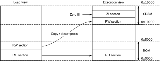
LOAD_ROM 0x0000 0x8000       ; Name of load region (LOAD_ROM),
                             ; Start address for load region (0x0000),
                             ; Maximum size of load region (0x8000)
{
     0x0000 0x8000   ; Name of first exec region (EXEC_ROM),
                             ; Start address for exec region (0x0000),
                             ; Maximum size of first exec region (0x8000)
    {
        * (+RO)              ; Place all code and RO data into
                             ; this exec region
    }
    SRAM 0x10000 0x6000      ; Name of second exec region (SRAM),
                             ; Start address of second exec region (0x10000),
                             ; Maximum size of second exec region (0x6000)
    {
        * (+RW, +ZI)         ; Place all RW and ZI data into
                             ; this exec region
    }
}
armlink --ro_base 0x0 --rw_base 0x100007.5 Scatter-loading images with a complex memory map
For images with a complex memory map, you cannot specify the memory map using only linker command-line options. Such images require the use of a scatter file.
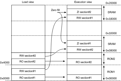
LOAD_ROM_1 0x0000              ; Start address for first load region (0x0000)
{
    EXEC_ROM_1 0x0000          ; Start address for first exec region (0x0000)
    {
        program1.o (+RO)       ; Place all code and RO data from
                               ; program1.o into this exec region
    }
    DRAM 0x18000 0x8000        ; Start address for this exec region (0x18000),
                               ; Maximum size of this exec region (0x8000)
    {
        program1.o (+RW, +ZI)  ; Place all RW and ZI data from
                               ; program1.o into this exec region
    }
}
LOAD_ROM_2 0x4000              ; Start address for second load region (0x4000)
{
    EXEC_ROM_2 0x4000
    {
        program2.o (+RO)       ; Place all code and RO data from
                               ; program2.o into this exec region
    }
    SRAM 0x8000 0x8000
    {
        program2.o (+RW, +ZI)  ; Place all RW and ZI data from
                               ; program2.o into this exec region
    }
}
Caution
* or .ANY specifier to place leftover code and data.7.6 Scatter file with link to bit-band objects
In devices with the ARMv7-M architecture, the SRAM and Peripheral regions each have a bit-band feature.
0x20000001, you can use the address 0x22000054.Table 7-1 ARMv7-M bit-band regions and aliases
|
Memory region
|
Description
|
Address range
|
|---|---|---|
|
SRAM
|
Bit-band region
|
0x20000000-0x200FFFFF
|
|
Bit-band alias
|
0x22000000-0x23FFFFFF
|
|
|
Peripheral
|
Bit-band region
|
0x40000000-0x400FFFFF
|
|
Bit-band alias
|
0x42000000-0x43FFFFFF
|
FLASH_LOAD 0x20000000
{
    RW 0x20000000  ; RW data at the start of bit band region
  {
    * (+RW-DATA)
  }
  RO +0 FIXED        ; Followed by the RO Data
  {
     * (+RO-DATA)
  }
  CODEDATA +0   ; Followed by everything else
  {
    * (+RO-CODE)
    * (+ZI)             ; ZI follows straight after
  }
  ARM_LIB_HEAP  +0 EMPTY 0x10000  ; heap starts after that
  {
  }
  ARM_LIB_STACK 0x20100000 EMPTY -0x10000    ; stack starts at the
                                             ; top of bit band region
  {
  }
}
7.12 Methods of placing functions and data at specific addresses
There are various methods available to place functions and data at specific addresses.
-
You can create a scatter file that defines an execution region at the required address with a section description that selects only one section.
-
For a specially-named section the linker can get the placement address from the section name. These specially-named sections are called
__atsections.
-
Place the function or data item in its own source file.
-
Use
__attribute__((at(to place variables in a separate section at a specific address.address))) -
Use
__attribute__((section("to place functions and variables in a named section.name"))) -
Use the
AREAdirective from assembly language. In assembly code, the smallest locatable unit is anAREA. -
Use the
--split_sectionscompiler option to generate one ELF section for each function in the source file.This option results in a small increase in code size for some functions because it reduces the potential for sharing addresses, data, and string literals between functions. However, this can help to reduce the final image size overall by enabling the linker to remove unused functions when you specifyarmlink --remove.
Example of how to place a variable at a specific address without scatter-loading
-
Create the source file main.c containing the following code:
#include <stdio.h>
extern int sqr(int n1);
int gSquared __attribute__((at(0x5000)));  // Place at 0x5000
int main()
{
    gSquared=sqr(3);
    printf("Value squared is: %d\n", gSquared);
}
-
Create the source file function.c containing the following code:
int sqr(int n1)
{
    return n1*n1;
}
-
Compile and link the sources:
armcc -c -g function.c
armcc -c -g main.c
armlink --map function.o main.o -o squared.axf
The--mapoption displays the memory map of the image. Also,--autoatis the default.
__attribute__((at(0x5000))) specifies that the global variable gSquared is to be placed at the absolute address 0x5000. gSquared is placed in the execution region ER$$.ARM.__at_0x00005000 and load region LR$$.ARM.__at_0x00005000.Note
0x5000 in the source file, the region names and section name addresses are normalized to eight hexadecimal digits.… Load Region LR$$.ARM.__at_0x00005000 (Base: 0x00005000, Size: 0x00000000, Max: 0x00000004, ABSOLUTE) Execution Region ER$$.ARM.__at_0x00005000 (Base: 0x00005000, Size: 0x00000004, Max: 0x00000004, ABSOLUTE, UNINIT) Base Addr Size Type Attr Idx E Section Name Object 0x00005000 0x00000004 Zero RW 13 .ARM.__at_0x00005000 main.o
Example of how to place a variable in a named section with scatter-loading
-
Create the source file main.c containing the following code:
#include <stdio.h>
extern int sqr(int n1);
int gSquared __attribute__((section("foo")));  // Place in section foo
int main()
{
    gSquared=sqr(3);
    printf("Value squared is: %d\n", gSquared);
}
-
Create the source file function.c containing the following code:
int sqr(int n1)
{
    return n1*n1;
}
-
Create the scatter file scatter.scat containing the following load region:
LR1 0x0000 0x20000
{
    ER1 0x0 0x2000
    {
        *(+RO)                ; rest of code and read-only data
    }
    ER2 0x8000 0x2000
    {
        main.o
    }
    ER3 0x10000 0x2000
    {
        function.o
        *(foo)                ; Place gSquared in ER3
    }
    ; RW and ZI data to be placed at 0x200000
    RAM 0x200000 (0x1FF00-0x2000)
    {
        *(+RW, +ZI)
    }
    ARM_LIB_STACK 0x800000 EMPTY -0x10000
    {
    }
    ARM_LIB_HEAP  +0 EMPTY 0x10000
    {
    }
}
TheARM_LIB_STACKandARM_LIB_HEAPregions are required because the program is being linked with the semihosting libraries. -
Compile and link the sources:
armcc -c -g function.c
armcc -c -g main.c
armlink --map --scatter=scatter.scat function.o main.o -o squared.axf
The--mapoption displays the memory map of the image. Also,--autoatis the default.
__attribute__((section("foo"))) specifies that the global variable gSquared is to be placed in a section called foo. The scatter file specifies that the section foo is to be placed in the ER3 execution region.Load Region LR1 (Base: 0x00000000, Size: 0x00001570, Max: 0x00020000, ABSOLUTE) … Execution Region ER3 (Base: 0x00010000, Size: 0x00000010, Max: 0x00002000, ABSOLUTE) Base Addr Size Type Attr Idx E Section Name Object 0x00010000 0x0000000c Code RO 3 .text function.o 0x0001000c 0x00000004 Data RW 15 foo main.o …
Note
*(foo) from the scatter file, the section is placed in the region of the same type. That is RAM in this example.Example of how to place a variable at a specific address with scatter-loading
-
Create the source file main.c containing the following code:
#include <stdio.h>
extern int sqr(int n1);
// Place at address 0x10000
const int gValue __attribute__((section(".ARM.__at_0x10000"))) = 3;
int main()
{
    int squared;
    squared=sqr(gValue);
    printf("Value squared is: %d\n", squared);
}
-
Create the source file function.c containing the following code:
int sqr(int n1)
{
    return n1*n1;
}
-
Create the scatter file scatter.scat containing the following load region:
LR1 0x0
{
    ER1 0x0
    {
        *(+RO)                      ; rest of code and read-only data
    }
    ER2 +0
    {
        function.o
        *(.ARM.__at_0x10000)        ; Place gValue at 0x10000
    }
    ; RW and ZI data to be placed at 0x200000
    RAM 0x200000 (0x1FF00-0x2000)
    {
        *(+RW, +ZI)
    }
    ARM_LIB_STACK 0x800000 EMPTY -0x10000
    {
    }
    ARM_LIB_HEAP  +0 EMPTY 0x10000
    {
    }
}
TheARM_LIB_STACKandARM_LIB_HEAPregions are required because the program is being linked with the semihosting libraries. -
Compile and link the sources:
armcc -c -g function.c
armcc -c -g main.c
armlink --no_autoat --scatter=scatter.scat --map function.o main.o -o squared.axf
The--mapoption displays the memory map of the image.
ER2 execution region at address 0x10000:… Execution Region ER2 (Base: 0x00001578, Size: 0x0000ea8c, Max: 0xffffffff, ABSOLUTE) Base Addr Size Type Attr Idx E Section Name Object 0x00001578 0x0000000c Code RO 3 .text function.o 0x00001584 0x0000ea7c PAD 0x00010000 0x00000004 Data RO 15 .ARM.__at_0x10000 main.o …
ER1 is uknown. Therefore, gValue might be placed in ER1 or ER2. To make sure that gValue is placed in ER2, you must include the corresponding selector in ER2 and link with the --no_autoat command-line option. If you omit --no_autoat, gValue is to placed in a separate load region LR$$.ARM.__at_0x10000 that contains the execution region ER$$.ARM.__at_0x.ARM.__at_0x10000.7.15 Examples of using placement algorithms for .ANY sections
These examples show the operation of the placement algorithms for RO-CODE sections in sections.o.
Table 7-2 Input section properties for placement of .ANY sections
| Name | Size |
|---|---|
sec1 |
0x4 |
sec2 |
0x4 |
sec3 |
0x4 |
sec4 |
0x4 |
sec5 |
0x4 |
sec6 |
0x4 |
LR 0x100
{
  ER_1 0x100 0x10
  {
     .ANY
  }
  ER_2 0x200 0x10
  {
     .ANY
  }
}
Note
--any_contingency disabled.Example for first_fit, next_fit, and best_fit
.ANY(+R0) and have no priority.Execution Region ER_1 (Base: 0x00000100, Size: 0x00000010, Max: 0x00000010, ABSOLUTE) Base Addr Size Type Attr Idx E Section Name Object 0x00000100 0x00000004 Code RO 1 sec1 sections.o 0x00000104 0x00000004 Code RO 2 sec2 sections.o 0x00000108 0x00000004 Code RO 3 sec3 sections.o 0x0000010c 0x00000004 Code RO 4 sec4 sections.o Execution Region ER_2 (Base: 0x00000200, Size: 0x00000008, Max: 0x00000010, ABSOLUTE) Base Addr Size Type Attr Idx E Section Name Object 0x00000200 0x00000004 Code RO 5 sec5 sections.o 0x00000204 0x00000004 Code RO 6 sec6 sections.o
-
For
first_fitthe linker first assigns all the sections it can toER_1, then moves on toER_2because that is the next available region. -
For
next_fitthe linker does the same asfirst_fit. However, whenER_1is full it is marked asFULLand is not considered again. In this example,ER_1is completely full.ER_2is then considered. -
For
best_fitthe linker assignssec1toER_1. It then has two regions of equal priority and specificity, butER_1has less space remaining. Therefore, the linker assignssec2toER_1, and continues assigning sections untilER_1is full.
Example for worst_fit
worst_fit algorithm.Execution Region ER_1 (Base: 0x00000100, Size: 0x0000000c, Max: 0x00000010, ABSOLUTE) Base Addr Size Type Attr Idx E Section Name Object 0x00000100 0x00000004 Code RO 1 sec1 sections.o 0x00000104 0x00000004 Code RO 3 sec3 sections.o 0x00000108 0x00000004 Code RO 5 sec5 sections.o Execution Region ER_2 (Base: 0x00000200, Size: 0x0000000c, Max: 0x00000010, ABSOLUTE) Base Addr Size Type Attr Idx E Section Name Object 0x00000200 0x00000004 Code RO 2 sec2 sections.o 0x00000204 0x00000004 Code RO 4 sec4 sections.o 0x00000208 0x00000004 Code RO 6 sec6 sections.o
sec1 to ER_1. It then has two equally specific and priority regions. It assigns sec2 to the one with the most free space, ER_2 in this example. The regions now have the same amount of space remaining, so the linker assigns sec3 to the first one that appears in the scatter file, that is ER_1.Note
worst_fit is the default behavior in this version of the linker, and it is the only algorithm available and earlier linker versions.7.16 Example of next_fit algorithm showing behavior of full regions, selectors, and priority
This example shows the operation of the next_fit placement algorithm for RO-CODE sections in sections.o.
Table 7-3 Input section properties for placement of sections with next_fit
| Name | Size |
|---|---|
sec1 |
0x14 |
sec2 |
0x14 |
sec3 |
0x10 |
sec4 |
0x4 |
sec5 |
0x4 |
sec6 |
0x4 |
LR 0x100
{
  ER_1 0x100 0x20
  {
     .ANY1(+RO-CODE)
  }
  ER_2 0x200 0x20
  {
     .ANY2(+RO)
  }
  ER_3 0x300 0x20
  {
     .ANY3(+RO)
  }
}
Note
--any_contingency disabled.next_fit algorithm is different to the others in that it never revisits a region that is considered to be full. This example also shows the interaction between priority and specificity of selectors - this is the same for all the algorithms.Execution Region ER_1 (Base: 0x00000100, Size: 0x00000014, Max: 0x00000020, ABSOLUTE) Base Addr Size Type Attr Idx E Section Name Object 0x00000100 0x00000014 Code RO 1 sec1 sections.o Execution Region ER_2 (Base: 0x00000200, Size: 0x0000001c, Max: 0x00000020, ABSOLUTE) Base Addr Size Type Attr Idx E Section Name Object 0x00000200 0x00000010 Code RO 3 sec3 sections.o 0x00000210 0x00000004 Code RO 4 sec4 sections.o 0x00000214 0x00000004 Code RO 5 sec5 sections.o 0x00000218 0x00000004 Code RO 6 sec6 sections.o Execution Region ER_3 (Base: 0x00000300, Size: 0x00000014, Max: 0x00000020, ABSOLUTE) Base Addr Size Type Attr Idx E Section Name Object 0x00000300 0x00000014 Code RO 2 sec2 sections.o
-
The linker places
sec1inER_1becauseER_1has the most specific selector.ER_1now has0x6bytes remaining. -
The linker then tries to place
sec2inER_1, because it has the most specific selector, but there is not enough space. Therefore,ER_1is marked as full and is not considered in subsequent placement steps. The linker choosesER_3forsec2because it has higher priority thanER_2. -
The linker then tries to place
sec3inER_3. It does not fit, soER_3is marked as full and the linker placessec3inER_2. -
The linker now processes
sec4. This is0x4bytes so it can fit in eitherER_1orER_3. Because both of these sections have previously been marked as full, they are not considered. The linker places all remaining sections inER_2. -
If another section
sec7of size0x8exists, and is processed aftersec6the example fails to link. The algorithm does not attempt to place the section inER_1orER_3because they have previously been marked as full.
7.19 Placement of code and data with __attribute__((section("name")))
You can place code and data by separating them into their own objects without having to use toolchain-specific pragmas or attributes.
__attribute__((section("name"))) to place an item in a separate ELF section. You can then use a scatter file to place the named sections at specific locations.Examples
__attribute__((section("name"))) to place a variable in a separate section:-
Use
__attribute__((section("to specify the named section where the variable is to be placed, for example:name")))- Naming a section
-
int variable __attribute__((section("foo"))) = 10;
-
Use a scatter file to place the named section, for example:
- Placing a section
-
FLASH 0x24000000 0x4000000
{
    …                                ; rest of code
    ADDER 0x08000000
    {
        file.o (foo)                  ; select section foo from file.o
    }
}
FLASH load region:… Load Region FLASH (Base: 0x24000000, Size: 0x00000004, Max: 0x04000000, ABSOLUTE) Execution Region ADDER (Base: 0x08000000, Size: 0x00000004, Max: 0xffffffff, ABSOLUTE) Base Addr Size Type Attr Idx E Section Name Object 0x08000000 0x00000004 Data RW 16 foo file.o …
-
Linking with
--autoator--no_autoatdoes not affect the placement. -
If scatter-loading is not used, the section is placed in the default
ER_RWexecution region of theLR_1load region. -
If you have a scatter file that does not include the
fooselector, then the section is placed in the defined RW execution region.
.ARM.__at_address as the section name. For example, to place the function sqr at 0x20000, specify:int sqr(int n1) __attribute__((section(".ARM.__at_0x20000"))); int sqr(int n1) { return n1*n1; }


 浙公网安备 33010602011771号